EP1183498B1 - Stellungsgeber mit flusstoraufnehmern - Google Patents
Stellungsgeber mit flusstoraufnehmern Download PDFInfo
- Publication number
- EP1183498B1 EP1183498B1 EP00930811A EP00930811A EP1183498B1 EP 1183498 B1 EP1183498 B1 EP 1183498B1 EP 00930811 A EP00930811 A EP 00930811A EP 00930811 A EP00930811 A EP 00930811A EP 1183498 B1 EP1183498 B1 EP 1183498B1
- Authority
- EP
- European Patent Office
- Prior art keywords
- sensor
- axis
- radial
- signal
- pair
- Prior art date
- Legal status (The legal status is an assumption and is not a legal conclusion. Google has not performed a legal analysis and makes no representation as to the accuracy of the status listed.)
- Expired - Lifetime
Links
Images


Classifications
-
- G—PHYSICS
- G01—MEASURING; TESTING
- G01R—MEASURING ELECTRIC VARIABLES; MEASURING MAGNETIC VARIABLES
- G01R33/00—Arrangements or instruments for measuring magnetic variables
- G01R33/02—Measuring direction or magnitude of magnetic fields or magnetic flux
- G01R33/04—Measuring direction or magnitude of magnetic fields or magnetic flux using the flux-gate principle
-
- G—PHYSICS
- G01—MEASURING; TESTING
- G01D—MEASURING NOT SPECIALLY ADAPTED FOR A SPECIFIC VARIABLE; ARRANGEMENTS FOR MEASURING TWO OR MORE VARIABLES NOT COVERED IN A SINGLE OTHER SUBCLASS; TARIFF METERING APPARATUS; MEASURING OR TESTING NOT OTHERWISE PROVIDED FOR
- G01D5/00—Mechanical means for transferring the output of a sensing member; Means for converting the output of a sensing member to another variable where the form or nature of the sensing member does not constrain the means for converting; Transducers not specially adapted for a specific variable
- G01D5/12—Mechanical means for transferring the output of a sensing member; Means for converting the output of a sensing member to another variable where the form or nature of the sensing member does not constrain the means for converting; Transducers not specially adapted for a specific variable using electric or magnetic means
- G01D5/14—Mechanical means for transferring the output of a sensing member; Means for converting the output of a sensing member to another variable where the form or nature of the sensing member does not constrain the means for converting; Transducers not specially adapted for a specific variable using electric or magnetic means influencing the magnitude of a current or voltage
- G01D5/20—Mechanical means for transferring the output of a sensing member; Means for converting the output of a sensing member to another variable where the form or nature of the sensing member does not constrain the means for converting; Transducers not specially adapted for a specific variable using electric or magnetic means influencing the magnitude of a current or voltage by varying inductance, e.g. by a movable armature
- G01D5/22—Mechanical means for transferring the output of a sensing member; Means for converting the output of a sensing member to another variable where the form or nature of the sensing member does not constrain the means for converting; Transducers not specially adapted for a specific variable using electric or magnetic means influencing the magnitude of a current or voltage by varying inductance, e.g. by a movable armature differentially influencing two coils
- G01D5/2208—Mechanical means for transferring the output of a sensing member; Means for converting the output of a sensing member to another variable where the form or nature of the sensing member does not constrain the means for converting; Transducers not specially adapted for a specific variable using electric or magnetic means influencing the magnitude of a current or voltage by varying inductance, e.g. by a movable armature differentially influencing two coils by influencing the self-induction of the coils
- G01D5/2216—Mechanical means for transferring the output of a sensing member; Means for converting the output of a sensing member to another variable where the form or nature of the sensing member does not constrain the means for converting; Transducers not specially adapted for a specific variable using electric or magnetic means influencing the magnitude of a current or voltage by varying inductance, e.g. by a movable armature differentially influencing two coils by influencing the self-induction of the coils by a movable ferromagnetic element, e.g. a core
-
- G—PHYSICS
- G01—MEASURING; TESTING
- G01P—MEASURING LINEAR OR ANGULAR SPEED, ACCELERATION, DECELERATION, OR SHOCK; INDICATING PRESENCE, ABSENCE, OR DIRECTION, OF MOVEMENT
- G01P3/00—Measuring linear or angular speed; Measuring differences of linear or angular speeds
- G01P3/42—Devices characterised by the use of electric or magnetic means
- G01P3/44—Devices characterised by the use of electric or magnetic means for measuring angular speed
- G01P3/48—Devices characterised by the use of electric or magnetic means for measuring angular speed by measuring frequency of generated current or voltage
- G01P3/481—Devices characterised by the use of electric or magnetic means for measuring angular speed by measuring frequency of generated current or voltage of pulse signals
- G01P3/487—Devices characterised by the use of electric or magnetic means for measuring angular speed by measuring frequency of generated current or voltage of pulse signals delivered by rotating magnets
Landscapes
- Physics & Mathematics (AREA)
- General Physics & Mathematics (AREA)
- Condensed Matter Physics & Semiconductors (AREA)
- Transmission And Conversion Of Sensor Element Output (AREA)
- Measuring Magnetic Variables (AREA)
- Measurement Of Length, Angles, Or The Like Using Electric Or Magnetic Means (AREA)
Claims (7)
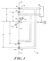
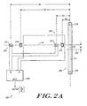
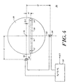
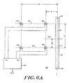
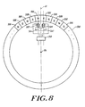
- Stellungsgeber zur Lieferung eines im Wesentlichen linearen Ausgangssignals, das eine Position eines beweglichen magnetischen Elementes bezüglich einer Bezugsposition darstellt, mit:dem magnetischen Element (106; 206), das entgegengesetzte Magnetpole (118, 120; 218, 220) aufweist, die entlang einer Polachse angeordnet sind und ein Magnetfeld erzeugen;einem ersten räumlich orthogonalen Magnetfeldsensor-Paar (102; 202) zum Detektieren des Magnetfeldes, wobei das erste Sensor-Paar einen tangentialen ersten Feldsensor (110; 210) und einen radialen zweiten Feldsensor (110; 212) aufweist und benachbart zu der Pol-Achse an einer ersten vorgegebenen Entfernung und bezüglich der Bezugsposition festgelegt angeordnet ist, und einem zweiten räumlich orthogonalen Magnetfeld-Sensorpaar (104; 204) zur Detektion des Magnetfeldes, wobei das zweite Paar einen tangentialen dritten Feld-Sensor (114; 214) und einen radialen vierten Feld-Sensor (116; 216) einschließt und benachbart zu der Pol-Achse an einem zweiten vorgegebenen Abstand und bezüglich der Bezugsposition festgelegt angeordnet ist,wobei die Position des beweglichen Körpers entweder: eine Winkelposition einschließt, wobei der bewegliche Körper eine drehbare Welle mit einer Drehachse (RA) einschließt und das magnetische Element (106) eine mittlere Drehebene im Wesentlichen unter einem rechten Winkel zu der Drehachse (RA) definiert, wobei alle Sensoren entlang einer Sensor-Achse (SA) innerhalb der mittleren Drehebene unter einem rechten Winkel zu der Drehachse (RA) angeordnet sind; odereine geradlinige Position einschließt, wobei das bewegliche magnetische Element ein langgestrecktes Stabelement (218), das entlang einer Bewegungsachse (LA) parallel zu der Pol-Achse (PA) angeordnet ist, einschließt, und die ersten und zweiten Sensor-Paare bezüglich der Bezugsposition festgelegt sind und alle Sensoren entlang einer Achse im Wesentlichen unter einem rechten Winkel zu der Bewegungsachse angeordnet sind;wobei der tangentiale erste Feldsensor (110; 210) des ersten Sensor-Paares in einem Abstand R1, der tangentiale dritte Feld-Sensor (114; 214) des zweiten Sensor-Paares in einem Abstand R2, der radiale zweite Feld-Sensor (112; 212) des ersten Sensor-Paares in einem R3 und der radiale vierte Feld-Sensor (116; 216) des zweiten Sensor-Paares in einem Abstand von R4 angeordnet ist, wobei die Abstände R1, R2, R3 und R4 so gewählt sind, dass ein erstes Verhältnis R3/R1 im Wesentlichen gleich einem ersten vorgegebenen Wert ist, ein zweites Verhältnis R4/R2 im Wesentlichen gleich einem zweiten vorgegebenen Wert ist, ein drittes Verhältnis R2/R1 im Wesentlichen gleich einem dritten vorgegebenen Wert ist, und ein viertes Verhältnis R4/R3 im Wesentlichen gleich einem vierten vorgegebenen Wert ist,wobei der erste Feld-Sensor und der dritte Feld-Sensor elektrisch entgegengesetzt zueinander in Serie angeordnet sind, um ein erstes zusammengesetztes Signal zu erzeugen, und der zweite Feld-Sensor und der vierte Feld-Sensor elektrisch entgegengesetzt zueinander in Serie geschaltet sind, um ein zweites zusammengesetztes Signal zu erzeugen; undeinem Signalprozessor (108; 208) zum Empfang des ersten zusammengesetzten Signals und des zweiten zusammengesetzten Signals und zur Erzeugung des Ausgangssignals als eine Funktion der ersten und zweiten zusammengesetzten Signale.
- Stellungsgeber nach Anspruch 1, bei dem der erste vorgegebene Abstand kleiner als der zweite vorgegebene Abstand ist.
- Stellungsgeber nach Anspruch 3, bei dem der erste vorgegebene Abstand im Wesentlichen gleich einer Hälfte des zweiten vorgegebenen Abstandes ist.
- Stellungsgeber nach einem der Ansprüche 1 bis 3, bei dem das erste Sensor-Paar (102; 202) und das zweite Sensor-Paar (104; 204) jeweils einen radialen Sensor zum Messen einer Radial-Komponente des Magnetfeldes und einen tangentialen Sensor zur Messung einer tangentialen Komponente des Magnetfeldes einschließen.
- Stellungsgeber nach einem der Ansprüche 1 bis 4, bei dem der erste vorgegebene Wert 21/3 ist, der zweite vorgegebene Wert 21/3 ist, der dritte vorgegebene Wert gleich 2 ist und der vierte vorgegebene Wert 2 ist.
- Stellungsgeber nach einem der vorhergehenden Ansprüche, der weiterhin ein Temperatur-Messelement zur Feststellung einer Temperatur der ersten und zweiten Magnetfeldsonden-Paare und zur Kompensation des Ausgangssignals als eine vorgegebene Funktion der Temperatur einschließt.
- Stellungsgeber nach einem der vorhergehenden Ansprüche, der weiterhin ein Temperatur-Sensorelement zur Feststellung der Temperatur des magnetischen Elementes und zur Kompensation des Ausgangssignals als eine vorgegebene Funktion der Temperatur einschließt.
Applications Claiming Priority (3)
| Application Number | Priority Date | Filing Date | Title |
|---|---|---|---|
| US09/315,205 US6265867B1 (en) | 1999-05-19 | 1999-05-19 | Position encoder utilizing fluxgate sensors |
| US315205 | 1999-05-19 | ||
| PCT/US2000/013657 WO2000070300A1 (en) | 1999-05-19 | 2000-05-18 | Position encoder utilizing fluxgate sensors |
Publications (3)
| Publication Number | Publication Date |
|---|---|
| EP1183498A1 EP1183498A1 (de) | 2002-03-06 |
| EP1183498A4 EP1183498A4 (de) | 2002-07-31 |
| EP1183498B1 true EP1183498B1 (de) | 2011-11-02 |
Family
ID=23223356
Family Applications (1)
| Application Number | Title | Priority Date | Filing Date |
|---|---|---|---|
| EP00930811A Expired - Lifetime EP1183498B1 (de) | 1999-05-19 | 2000-05-18 | Stellungsgeber mit flusstoraufnehmern |
Country Status (6)
| Country | Link |
|---|---|
| US (1) | US6265867B1 (de) |
| EP (1) | EP1183498B1 (de) |
| JP (1) | JP4907770B2 (de) |
| AT (1) | ATE532028T1 (de) |
| CA (1) | CA2373381C (de) |
| WO (1) | WO2000070300A1 (de) |
Families Citing this family (27)
| Publication number | Priority date | Publication date | Assignee | Title |
|---|---|---|---|---|
| EP1243897B1 (de) * | 2001-03-23 | 2013-12-18 | Melexis Technologies NV | Magnetischer Weggeber |
| DE10133428C1 (de) * | 2001-07-10 | 2003-03-13 | Continental Ag | Fahrzeugreifen sowie Anordnung und Verfahren zur Messung der Verformung von Fahrzeugreifen |
| US6949924B2 (en) * | 2001-07-26 | 2005-09-27 | Adaptive Instruments Llc | Electromechanical rotation sensing device |
| US7521923B2 (en) * | 2002-04-23 | 2009-04-21 | Abas, Incorporated | Magnetic displacement transducer |
| AU2003249289A1 (en) * | 2002-07-17 | 2004-02-02 | The Timken Company | Apparatus and method for absolute angular position sensing |
| EP1565755B2 (de) * | 2002-11-20 | 2023-07-05 | Avago Technologies International Sales Pte. Limited | Positionsdetektor |
| US6853184B2 (en) * | 2002-12-02 | 2005-02-08 | Honeywell International Inc. | Methods and systems for utilizing a ring magnet for magnetic sensing applications |
| FR2856145B1 (fr) * | 2003-06-16 | 2005-09-02 | Michelin Soc Tech | Detection des revolutions d'un ensemble pneumatique et roue, a l'aide du champ magnetique terrestre. |
| DE602005007580D1 (de) † | 2004-03-01 | 2008-07-31 | Sagentia Ltd | Positionssensor |
| GB0427410D0 (en) * | 2004-12-14 | 2005-01-19 | Kreit Darran | Data acquisition system |
| DE102005010121B4 (de) * | 2005-03-02 | 2007-09-27 | Carl Freudenberg Kg | Encoder |
| DE102005032145A1 (de) * | 2005-07-07 | 2007-01-11 | Zf Friedrichshafen Ag | Gelenk für ein Kraftfahrzeug |
| EP1744136B1 (de) * | 2005-07-11 | 2009-05-06 | NCTEngineering GmbH | Drehwinkelsensor |
| WO2007121373A2 (en) * | 2006-04-13 | 2007-10-25 | Tiax Llc | Sensor system |
| DE102007036271A1 (de) * | 2007-07-31 | 2009-02-05 | Baumer Hübner GmbH | Drehgeber mit Überwachung des Lagerverschleißes sowie Verfahren hierzu |
| DE102007039050B8 (de) * | 2007-08-17 | 2024-02-15 | Avago Technologies International Sales Pte. Limited | Linearsegment- oder Umdrehungszähler mit einem ferromagnetischen Element |
| FR2926889B1 (fr) * | 2008-01-30 | 2010-12-10 | Continental Automotive France | Procede de detection du deplacement d'un vehicule et dispositif correspondant |
| US8710827B2 (en) | 2008-03-19 | 2014-04-29 | Sagentia Limited | Processing circuitry for use with a position sensor |
| CA2771727C (en) | 2009-11-04 | 2013-01-08 | Technologies Numetrix Inc. | Device and method for obtaining three-dimensional object surface data |
| DE102010055736A1 (de) * | 2010-12-22 | 2012-06-28 | Festo Ag & Co. Kg | Verfahren zur Auswertung von Sensorsignalen sowie hierzu geeignete Sensoranordnung |
| US9562986B2 (en) * | 2011-07-01 | 2017-02-07 | Rapiscan Systems, Inc. | Walk through metal detection system |
| US9018942B2 (en) * | 2013-01-11 | 2015-04-28 | Bourns, Inc. | Position measurement using a variable flux collector |
| JP6233455B1 (ja) * | 2016-06-09 | 2017-11-22 | 愛知製鋼株式会社 | 回転機 |
| US10048091B1 (en) * | 2017-05-30 | 2018-08-14 | Infineon Technologies Ag | Magnetic multimedia control element |
| US11573072B2 (en) | 2018-12-13 | 2023-02-07 | Analog Devices International Unlimited Company | Magnetic position determination systems and methods |
| US11519710B2 (en) | 2020-02-26 | 2022-12-06 | Honeywell Limited | High accuracy and high stability magnetic displacement sensor in the presence of electromagnetic interferences |
| CN113639789A (zh) * | 2021-07-20 | 2021-11-12 | 支付宝(杭州)信息技术有限公司 | 检测柜门关闭的系统和方法 |
Family Cites Families (23)
| Publication number | Priority date | Publication date | Assignee | Title |
|---|---|---|---|---|
| US3342070A (en) * | 1964-10-01 | 1967-09-19 | Rockwell Mfg Co | Fluid meter |
| US3605011A (en) | 1967-05-25 | 1971-09-14 | Honeywell Inc | Control apparatus |
| US3644825A (en) * | 1969-12-31 | 1972-02-22 | Texas Instruments Inc | Magnetic detection system for detecting movement of an object utilizing signals derived from two orthogonal pickup coils |
| US3824456A (en) | 1973-02-23 | 1974-07-16 | Atomic Energy Commission | Magnetometer flowmeter using permanent magnets and magnetometer elements aligned with the flow |
| US3855525A (en) * | 1973-10-05 | 1974-12-17 | Illinois Tool Works | Angular velocity sensor |
| US4088954A (en) | 1975-02-04 | 1978-05-09 | Nasa | Magnetometer with a miniature transducer and automatic scanning |
| US4293815A (en) | 1978-05-01 | 1981-10-06 | Century Geophysical Corporation | Fluxgate magnetometer circuit with earth's field elimination |
| US4384254A (en) | 1980-06-06 | 1983-05-17 | The United States Of America As Represented By The Secretary Of The Navy | Oscillator/driver circuit for fluxgate magnetometer |
| DE3438120A1 (de) * | 1984-10-18 | 1986-04-24 | Gebhard Balluff Fabrik feinmechanischer Erzeugnisse GmbH & Co, 7303 Neuhausen | Stoerfeldfester naeherungsschalter |
| EP0191223A3 (de) * | 1984-11-09 | 1988-02-24 | The Superior Electric Company | Magnetisch arbeitender Transduktor |
| US4719419A (en) * | 1985-07-15 | 1988-01-12 | Harris Graphics Corporation | Apparatus for detecting a rotary position of a shaft |
| US4717873A (en) * | 1985-11-12 | 1988-01-05 | Westinghouse Electric Corp. | Magnetic displacement transducer system having a magnet that is movable in a tube whose interior is exposed to a fluid and having at least one magnetometer outside the tube |
| US5124648A (en) | 1987-08-25 | 1992-06-23 | Analog Devices, Inc. | Single winding saturable core magnetometer with field nulling |
| US4859944A (en) | 1987-08-25 | 1989-08-22 | Analog Devices, Inc. | Single-winding magnetometer with oscillator duty cycle measurement |
| US5115197A (en) | 1990-03-26 | 1992-05-19 | Giusseppe Brandolino | Fluxgate sensor having adjustable core extending beyond a coil winding and a gradiometer incorporating a pair of sensors |
| US5170566A (en) | 1990-06-05 | 1992-12-15 | Arthur D. Little, Inc. | Means for reducing interference among magnetometer array elements |
| US5602472A (en) * | 1993-01-15 | 1997-02-11 | Hughes Electronics | Apparatus and method for determining angular position and rotational speed using a rotating magnet and a directional magnetometer |
| US5670877A (en) | 1994-12-05 | 1997-09-23 | Hughes Electronics | Shaft rotation sensor with magnetic sensors angularly spaced apart with respect to a magnetic source |
| US5560115A (en) | 1995-06-07 | 1996-10-01 | Arthur D. Little Enterprises, Inc. | Gimbaled magnetometer with inductive coupling |
| US5744950A (en) * | 1996-05-09 | 1998-04-28 | Ssi Technologies, Inc. | Apparatus for detecting the speed of a rotating element including signal conditioning to provide a fifty percent duty cycle |
| DE19621886C2 (de) * | 1996-05-31 | 2000-11-30 | Heidenhain Gmbh Dr Johannes | Magnetische Positionsmeßeinrichtung |
| DE19646251C2 (de) * | 1996-11-08 | 1998-11-12 | Continental Ag | Luftreifen mit Mitteln zur Beschaffung von Informationen, seine Verwendung und Vorrichtung zu seiner Herstellung |
| US6014025A (en) | 1998-02-24 | 2000-01-11 | Methode Electronics, Inc. | PWM flux-gate circuit for measuring magnitude and direction of a magnetic field |
-
1999
- 1999-05-19 US US09/315,205 patent/US6265867B1/en not_active Expired - Lifetime
-
2000
- 2000-05-18 CA CA2373381A patent/CA2373381C/en not_active Expired - Lifetime
- 2000-05-18 WO PCT/US2000/013657 patent/WO2000070300A1/en active Application Filing
- 2000-05-18 EP EP00930811A patent/EP1183498B1/de not_active Expired - Lifetime
- 2000-05-18 AT AT00930811T patent/ATE532028T1/de active
- 2000-05-18 JP JP2000618685A patent/JP4907770B2/ja not_active Expired - Lifetime
Also Published As
| Publication number | Publication date |
|---|---|
| ATE532028T1 (de) | 2011-11-15 |
| EP1183498A1 (de) | 2002-03-06 |
| US6265867B1 (en) | 2001-07-24 |
| CA2373381C (en) | 2010-04-13 |
| WO2000070300A1 (en) | 2000-11-23 |
| JP2002544509A (ja) | 2002-12-24 |
| CA2373381A1 (en) | 2000-11-23 |
| JP4907770B2 (ja) | 2012-04-04 |
| WO2000070300A9 (en) | 2002-06-27 |
| EP1183498A4 (de) | 2002-07-31 |
Similar Documents
| Publication | Publication Date | Title |
|---|---|---|
| EP1183498B1 (de) | Stellungsgeber mit flusstoraufnehmern | |
| JP4410566B2 (ja) | 移動および回転運動を検出する方法と装置 | |
| KR101721087B1 (ko) | 다중-주기 절대 위치 센서 | |
| US8373410B2 (en) | Rotary or linear position sensor having a variable magnet profile | |
| CN103154672B (zh) | 多圈磁性绝对位置检测装置 | |
| Treutler | Magnetic sensors for automotive applications | |
| CN108303562B (zh) | 退磁场鲁棒、扭转敏感的磁速传感器 | |
| US7215112B1 (en) | Non-contact linear absolute position sensor | |
| CN100520303C (zh) | 磁传感器装置 | |
| US7548060B2 (en) | Magnetic sensor system | |
| US20040017187A1 (en) | Magnetoresistive linear position sensor | |
| US6154025A (en) | Contactless potentiometer and device for contactlessly sensing a position of an object | |
| US8970210B2 (en) | Bidirectional magnetic position sensor having field rotation | |
| US6229299B1 (en) | System and method for computing the angular velocity and direction of a rotational body | |
| CN101680777B (zh) | 磁场传感器 | |
| US10876865B2 (en) | Encoder system for position determination with inclined scale | |
| Wang et al. | An angle displacement sensor using a simple gear | |
| US7463023B1 (en) | Non-contacting rotary and linear travel sensor | |
| JP2837563B2 (ja) | 軸上のトルクの測定装置 | |
| JPH03276014A (ja) | 磁気式回転角度検出器 | |
| JPH05196478A (ja) | 位置検出装置 | |
| JPH0197824A (ja) | トルク検出装置 | |
| JP4230576B2 (ja) | ウインドレギュレータ装置 | |
| JP2004150812A (ja) | トルクセンサ |
Legal Events
| Date | Code | Title | Description |
|---|---|---|---|
| PUAI | Public reference made under article 153(3) epc to a published international application that has entered the european phase |
Free format text: ORIGINAL CODE: 0009012 |
|
| 17P | Request for examination filed |
Effective date: 20011219 |
|
| AK | Designated contracting states |
Kind code of ref document: A1 Designated state(s): AT BE CH CY DE DK ES FI FR GB GR IE IT LI LU MC NL PT SE |
|
| A4 | Supplementary search report drawn up and despatched |
Effective date: 20020614 |
|
| AK | Designated contracting states |
Kind code of ref document: A4 Designated state(s): AT BE CH CY DE DK ES FI FR GB GR IE IT LI LU MC NL PT SE |
|
| RAP1 | Party data changed (applicant data changed or rights of an application transferred) |
Owner name: TIAX LLC |
|
| 17Q | First examination report despatched |
Effective date: 20050103 |
|
| 17Q | First examination report despatched |
Effective date: 20050103 |
|
| GRAP | Despatch of communication of intention to grant a patent |
Free format text: ORIGINAL CODE: EPIDOSNIGR1 |
|
| GRAS | Grant fee paid |
Free format text: ORIGINAL CODE: EPIDOSNIGR3 |
|
| GRAA | (expected) grant |
Free format text: ORIGINAL CODE: 0009210 |
|
| AK | Designated contracting states |
Kind code of ref document: B1 Designated state(s): AT BE CH CY DE DK ES FI FR GB GR IE IT LI LU MC NL PT SE |
|
| REG | Reference to a national code |
Ref country code: GB Ref legal event code: FG4D |
|
| REG | Reference to a national code |
Ref country code: CH Ref legal event code: EP |
|
| REG | Reference to a national code |
Ref country code: IE Ref legal event code: FG4D |
|
| REG | Reference to a national code |
Ref country code: DE Ref legal event code: R082 Ref document number: 60046627 Country of ref document: DE Representative=s name: KILBURN & STRODE LLP, GB |
|
| REG | Reference to a national code |
Ref country code: DE Ref legal event code: R096 Ref document number: 60046627 Country of ref document: DE Effective date: 20120119 |
|
| REG | Reference to a national code |
Ref country code: NL Ref legal event code: VDEP Effective date: 20111102 |
|
| PG25 | Lapsed in a contracting state [announced via postgrant information from national office to epo] |
Ref country code: PT Free format text: LAPSE BECAUSE OF FAILURE TO SUBMIT A TRANSLATION OF THE DESCRIPTION OR TO PAY THE FEE WITHIN THE PRESCRIBED TIME-LIMIT Effective date: 20120302 Ref country code: NL Free format text: LAPSE BECAUSE OF FAILURE TO SUBMIT A TRANSLATION OF THE DESCRIPTION OR TO PAY THE FEE WITHIN THE PRESCRIBED TIME-LIMIT Effective date: 20111102 Ref country code: BE Free format text: LAPSE BECAUSE OF FAILURE TO SUBMIT A TRANSLATION OF THE DESCRIPTION OR TO PAY THE FEE WITHIN THE PRESCRIBED TIME-LIMIT Effective date: 20111102 Ref country code: SE Free format text: LAPSE BECAUSE OF FAILURE TO SUBMIT A TRANSLATION OF THE DESCRIPTION OR TO PAY THE FEE WITHIN THE PRESCRIBED TIME-LIMIT Effective date: 20111102 Ref country code: GR Free format text: LAPSE BECAUSE OF FAILURE TO SUBMIT A TRANSLATION OF THE DESCRIPTION OR TO PAY THE FEE WITHIN THE PRESCRIBED TIME-LIMIT Effective date: 20120203 |
|
| PG25 | Lapsed in a contracting state [announced via postgrant information from national office to epo] |
Ref country code: CY Free format text: LAPSE BECAUSE OF FAILURE TO SUBMIT A TRANSLATION OF THE DESCRIPTION OR TO PAY THE FEE WITHIN THE PRESCRIBED TIME-LIMIT Effective date: 20111102 |
|
| PG25 | Lapsed in a contracting state [announced via postgrant information from national office to epo] |
Ref country code: DK Free format text: LAPSE BECAUSE OF FAILURE TO SUBMIT A TRANSLATION OF THE DESCRIPTION OR TO PAY THE FEE WITHIN THE PRESCRIBED TIME-LIMIT Effective date: 20111102 |
|
| PLBE | No opposition filed within time limit |
Free format text: ORIGINAL CODE: 0009261 |
|
| STAA | Information on the status of an ep patent application or granted ep patent |
Free format text: STATUS: NO OPPOSITION FILED WITHIN TIME LIMIT |
|
| REG | Reference to a national code |
Ref country code: AT Ref legal event code: MK05 Ref document number: 532028 Country of ref document: AT Kind code of ref document: T Effective date: 20111102 |
|
| 26N | No opposition filed |
Effective date: 20120803 |
|
| REG | Reference to a national code |
Ref country code: DE Ref legal event code: R097 Ref document number: 60046627 Country of ref document: DE Effective date: 20120803 |
|
| PG25 | Lapsed in a contracting state [announced via postgrant information from national office to epo] |
Ref country code: MC Free format text: LAPSE BECAUSE OF NON-PAYMENT OF DUE FEES Effective date: 20120531 |
|
| REG | Reference to a national code |
Ref country code: CH Ref legal event code: PL |
|
| GBPC | Gb: european patent ceased through non-payment of renewal fee |
Effective date: 20120518 |
|
| PG25 | Lapsed in a contracting state [announced via postgrant information from national office to epo] |
Ref country code: LI Free format text: LAPSE BECAUSE OF NON-PAYMENT OF DUE FEES Effective date: 20120531 Ref country code: AT Free format text: LAPSE BECAUSE OF FAILURE TO SUBMIT A TRANSLATION OF THE DESCRIPTION OR TO PAY THE FEE WITHIN THE PRESCRIBED TIME-LIMIT Effective date: 20111102 Ref country code: CH Free format text: LAPSE BECAUSE OF NON-PAYMENT OF DUE FEES Effective date: 20120531 |
|
| REG | Reference to a national code |
Ref country code: IE Ref legal event code: MM4A |
|
| REG | Reference to a national code |
Ref country code: FR Ref legal event code: ST Effective date: 20130131 |
|
| PG25 | Lapsed in a contracting state [announced via postgrant information from national office to epo] |
Ref country code: ES Free format text: LAPSE BECAUSE OF FAILURE TO SUBMIT A TRANSLATION OF THE DESCRIPTION OR TO PAY THE FEE WITHIN THE PRESCRIBED TIME-LIMIT Effective date: 20120213 Ref country code: FR Free format text: LAPSE BECAUSE OF NON-PAYMENT OF DUE FEES Effective date: 20120531 Ref country code: GB Free format text: LAPSE BECAUSE OF NON-PAYMENT OF DUE FEES Effective date: 20120518 Ref country code: IE Free format text: LAPSE BECAUSE OF NON-PAYMENT OF DUE FEES Effective date: 20120518 |
|
| PG25 | Lapsed in a contracting state [announced via postgrant information from national office to epo] |
Ref country code: FI Free format text: LAPSE BECAUSE OF FAILURE TO SUBMIT A TRANSLATION OF THE DESCRIPTION OR TO PAY THE FEE WITHIN THE PRESCRIBED TIME-LIMIT Effective date: 20111102 |
|
| PG25 | Lapsed in a contracting state [announced via postgrant information from national office to epo] |
Ref country code: LU Free format text: LAPSE BECAUSE OF NON-PAYMENT OF DUE FEES Effective date: 20120518 |
|
| PGFP | Annual fee paid to national office [announced via postgrant information from national office to epo] |
Ref country code: DE Payment date: 20190314 Year of fee payment: 20 Ref country code: IT Payment date: 20190513 Year of fee payment: 20 |
|
| REG | Reference to a national code |
Ref country code: DE Ref legal event code: R071 Ref document number: 60046627 Country of ref document: DE |