EP1182872A2 - Système de communication - Google Patents
Système de communication Download PDFInfo
- Publication number
- EP1182872A2 EP1182872A2 EP01118953A EP01118953A EP1182872A2 EP 1182872 A2 EP1182872 A2 EP 1182872A2 EP 01118953 A EP01118953 A EP 01118953A EP 01118953 A EP01118953 A EP 01118953A EP 1182872 A2 EP1182872 A2 EP 1182872A2
- Authority
- EP
- European Patent Office
- Prior art keywords
- communication system
- data
- communication
- terminal
- unit
- Prior art date
- Legal status (The legal status is an assumption and is not a legal conclusion. Google has not performed a legal analysis and makes no representation as to the accuracy of the status listed.)
- Granted
Links
Images


Classifications
-
- H—ELECTRICITY
- H04—ELECTRIC COMMUNICATION TECHNIQUE
- H04N—PICTORIAL COMMUNICATION, e.g. TELEVISION
- H04N7/00—Television systems
- H04N7/10—Adaptations for transmission by electrical cable
- H04N7/106—Adaptations for transmission by electrical cable for domestic distribution
Definitions
- the invention relates to a communication system according to the preamble of Claim 1.
- MATV / SMATV systems are already known, that is to say common antenna systems, the television signals from terrestrial transmitters or satellites received and lead to various system components that users assigned to the system.
- These systems essentially consist of a unit that receives the television signals from terrestrial transmitters or satellites, from a head unit, which adapts and amplifies the received signals, and from a distribution network, through which the signals to the system components transferred that are assigned to the system users.
- the number of users of these MATV / SMATV systems is at most a few One hundred limited; the signals that are distributed in the systems are in never generated in the respective network.
- a message system is already known from German patent application DE 3524094 A1 known, which is connected to a common antenna (30).
- the known system has an antenna cable (26) to which receiving stations (38) and a so-called exterior door control panel (10) is connected; it enables connections between the outer door control panel (10) and each exactly one receiving station (38).
- Exactly one analog channel is used for this, which is the same for all apartments that are connected to the system.
- the Allocation of this analog channel is controlled by a control center Is assigned to receiving stations, the control taking place in such a way that there is only one voice connection at a time.
- the object of the invention based on specifying a communication system of the type mentioned at the beginning, that allows further uses.
- the invention has a number of advantages.
- a first embodiment of the invention is advantageous Communication system designed in such a way that a central control unit Communication connections between at least two user terminals controls; the central control unit also controls communication connections, on which at least one user terminal and / or at least one other system unit and / or another communication system is involved.
- the function of the central control unit can, for example also by a user terminal and / or another system unit be exercised.
- the system according to the invention thus combines the advantages of a common antenna (MATV / SMATV) system with the advantages of a communication system, such as a private branch exchange for voice, Images and / or data. Among other things, it enables voice and data connections on the one hand between apartments of a residential complex with each other as well as at least one apartment and one gatekeeper or door communication unit on the other hand.
- a common antenna MATV / SMATV
- the communication system according to the invention is also with a connectable to another communication system, especially with a public one Fixed and / or mobile telecommunications network (cordless or "wireless" systems).
- the communication system is a signal processing unit (Head unit) has the signals that go beyond the minimum an antenna can be received, edited.
- the signal processing unit is controllable according to the invention, for example, by a user terminal.
- the System users thus get the advantageous option of a plurality of television channels entered into the system Select TV channels.
- the communication system according to the invention can also be done by a non-system unit or by external system administrators (Installers, specialists such as maintenance personnel, ...) configure or wait without these having to go to the location of the system.
- Another embodiment of the communication system according to the invention is characterized in that the communication system is configured in this way is that the communication links using digital signals to be controlled. This allows a variety of functions such as the administration of authorizations of the different system users implement in a comparatively simple manner.
- the signal processing unit has a memory is assigned, which contains service data with which services within or outside the communication system, in particular with a time delay (not in real time).
- a system unit e.g. user terminal, control device, Component of the signal processing unit
- Play a saved movie activate the operation of pre-programmed Facilities, visualization of images, query of Databases, etc.
- the memory is preferably not only for system units, but also for at least one further (external) communication system, in particular for one public landline or mobile telecommunications network, accessible.
- the memory is a hard disk or a removable storage medium such as a CD-ROM or a floppy disk.
- the user terminal is a telephone terminal and / or a data terminal, in particular a data processing device is.
- This enables the implementation of interactive services such as Internet, voice, data, video, and operations control services in the system.
- TDMA time division multiplexing
- Data language base This component is central because it is all internal connections (between user terminals and door system) processed or mediated. It is located in the communication center.
- Data voice terminal This component processes connections on the terminal side the user. It is located in the user terminal in the apartment of the user.
- Data language modem This component is essential for the functionality of the system. It is located on the one hand at the system headquarters and on the other other in user terminals and enables the establishment of connections between the system center and user terminals. In the communication system according to the invention works the data voice modem in the frequencies of the Return channel, while conventional DECT MODEMs in the frequency of 1.9 GHz work.
- RTC adapter This component is the interface between the user terminal and the telephone switching network and enables internal connections from a user's terminal to another terminal of the MATV / SMATV network; this component also enables connections from the door intercom to receive and outgoing and incoming connections to establish over the telephone switching network.
- the system according to the invention simultaneously enables at least one internal one Connection between people or facilities in the residential units among themselves and also connections between the door system and the Units.
- MATV / SMATV networks be enabled for remote operation control, parameters of the head units (6 in Figure 1) by system administrators and / or users of these networks an RS232 connection, over the telephone switching network or over the MATV / SMATV network can be controlled.
- Operation control unit This component is located in the communication center and edited the data by the data base received and converts this data into a for further processing suitable format.
- Control processor This component processes the operational control data of the head units and is located in the control device (2 in FIG. 1).
- This component is located in the control device (2nd in Figure 1) and enables the initiation of the operational control or signaling data the head unit via the telephone network.
- RS 232 interface bus This component enables input and output the data of the operational control or signaling data of the head unit a local computer (PC). It is located in the control unit and in the Communications center.
- PC local computer
- Interface bus 485 This component enables connections between the Control device (2 in Figure 1) and the devices that make up the head unit of the MATV / SMATV network integrated. It is located in the control device (2 in Figure 1) and in the communication center.
- the system according to the invention which is designed in this way, enables an adjustment to the users and administrators of the MATV / SMATV network and Maintaining the network on site without the need to travel as this task directly from any - authorized - user terminal or on site of the network administrator either by means of telephony equipment or via the Internet can be done.
- Another advantage of the system according to the invention is that To provide a visual information system to MATV / SMATV networks that consists of one or more television channels in the control device (2 in Figure 1) are formed, their generation and modification can take place via a telecommunications switching network, for example via a local computer (e.g. PC) via an RS 232 interface or via a User terminal.
- a local computer e.g. PC
- RS 232 interface e.g. RS 232 interface
- control processor realized in the control device (2 in Figure 1) and in an image generation system is arranged.
- Image generation system This system generates screen displays that over the SMATV / MATV network are transmitted. It consists of a control processor, a storage device, a subsystem that inserts images RG / PAL converter, a modulator and an output up converter. The image generation system is arranged in the control device (2 in FIG. 1).
- the system according to the invention thus enables the transmission of images User terminals over the telephone switching network, over a local one Computer (PC) or via a user terminal, as already described.
- PC Computer
- the communication system according to the invention can be a storage device which enable the acquisition and storage of images.
- Another advantage of the communication system according to the invention is in that data transfers between users of the MATV / SMATV network and the control device (2 in FIG. 1). at the same time enables the processing of this data by means of the data processor the system has. This enables different facilities, that can be connected to the MATV / SMATV network by different users over the telephone switching network, over a local computer or can be controlled via a user terminal.
- the communication system according to the invention a communication center 1, which has the function of the central control and is also shown in Figure 2, a control unit 2 ( Figure 4) and several User terminals 3 (Figure 5).
- the user terminals 3 are preferred Telephone devices or units that have a telephone device 8.
- On The user terminal forms the central communication terminal 51 (FIG. 7).
- the mentioned system components 1, 2, 3 and 51 are via connecting elements (Plug) 4 connected to a MATV / SMATV network 5 via connecting cable 41.
- the MATV / SMATV network consists of exactly one antenna cable 5, in particular from a coaxial cable, like this is also shown in Figure 8.
- the system according to the invention is designed in such a way that it is Communication connections between the central communication terminal 51 on the one hand and in each case one or more user terminals 3 (e.g. 301, 302, ... or 30n; Figure 8) on the other hand also communication connections between two and more user terminals 3 (e.g. 301, 302, ... or 30n; figure 8) manufactures. So in the communication system according to the invention for example a communication connection, in particular a telephone connection between the user terminal 301 and the user terminal 302 manufactured.
- the communication system according to the invention thus also offers the Functions of a telecommunications or private branch exchange.
- the system also controls communication connections on which another System unit (e.g. alarm sensors, data storage 58, etc.) and a user terminal 3 is involved.
- another System unit e.g. alarm sensors, data storage 58, etc.
- a user terminal 3 is involved.
- the control unit 2 is also with the communication center 1 and with various Units to which the head unit 6 of the MATV / SMATV system heard, via communication elements 7 by means of a connecting bus 71 connected.
- the user terminal 3 is with a telephone device 8, with a further communication system, in particular with a telephone switching system, via connecting elements or connections 9 by means of cables 91 and to at least one television 60 and / or a radio 61 by means of Cable 91 connected.
- the system according to the invention can be used with another Communication system also via the control center 1 or the control unit 2 be connected.
- the head unit 6 is a signal processing unit, the signals that over the at least one antenna are received, processed.
- the signal processing or head unit 6 is in the communication system according to the invention of system units (e.g. 1, 2, 3, 51, 58) and / or of one further communication system, in particular controllable from a telecommunications network.
- system units e.g. 1, 2, 3, 51, 58
- one further communication system in particular controllable from a telecommunications network.
- a memory 58 is assigned to the signal processing unit 6 and contains the service data contains services with which inside or outside the Communication system, in particular with a time delay (not in real time) become.
- a system unit e.g. user terminal, Control device, component of the signal processing unit
- the memory 58 is for system units and / or for at least one external one Communication system, especially for a fixed or mobile telecommunications network, accessible.
- the data stored in memory 58 is in System units and / or in at least one external communication system, especially transferable to a fixed or mobile telecommunications network.
- the memory 58 is, in particular, a hard disk, a CD-ROM or a floppy disk.
- more than one system unit can access the at the same time Memory 58 have to point to the same or different data contained in the Memory 58 are stored to access and / or to write data.
- the communication system according to the invention can continue in this way be designed so that information (operational information) between the Signal processing unit 6 and at least one user terminal 3 uni- or be transmitted bidirectionally.
- This information denotes operating states the signal processing unit 6 and / or the mode of operation thereof Unit 6.
- the user terminal 3 forms signals that indicate operating states and / or act on the functioning of the unit 6.
- This signal processing unit is a known head unit, for example Has amplifiers, converters, processors, transmodulators, etc.
- the head or signal processing unit forms a parameter selection menu and transmits this to a user terminal that the menu requests, for example with the intention of changing the parameters of the Change head unit.
- a user terminal and using the menu to transmit the information to the head unit that the A specific channel must be changed.
- Other examples of that Parameters are output voltage, audio and video level and change of one Receiving channel.
- Another operating information transmitted by a user terminal 3 is a software file that shows a modified operation of the head unit 6 Are defined.
- a person who has to manage the system can partially or completely control the operation of the head unit.
- the user terminals 3 and the unit 51 can have user authorizations be assigned; this includes new user permissions, the assignment of services to users, the blocking of services due to non-payment, system and service shutdowns, etc.
- the communication system can also be designed in such a way that Information (operational information) between the signal processing unit 6 and at least one other communication system unidirectional or bidirectional are transmitted, the information operating states of the signal processing unit 6 and / or the operation of this unit 6.
- the other communication system in particular a telephone network, forms Signals that relate to operating states and / or the functioning of the unit 6 act.
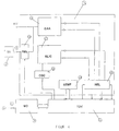
- Figure 2 shows a block diagram of the communication center 1.
- the communication center 1 consists of a data language base 11, a data voice modem 12, an operation control unit 13, from an interface bus 485 14 and an interface bus RS232 15.
- connection elements 4 for connection to the MATV / SMATV network 5
- connecting elements 7 for connection to the control unit 2 and various units in the head unit 6
- connecting elements 10 for connecting units that process input data and Form output data on.
- the data language base 11 consists of a microprocessor, for example works according to the DECT communication standard, and from one Memory that stores the operating software of the microprocessor.
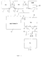
- the data voice modem 12 consists of an input / output / coupling element 16, an input bandpass filter 17 and one Output bandpass filter 18, which is the input-output stage of the device form.
- the input and output signals are switched by means of a switching arrangement 19 separated.
- the data voice modem 12 has a first one for processing the input signal Mixing circuit 20, the function of which is to convert the input signal into a Intermediate frequency (110 MHz) implement, the output signal of a stage the first intermediate frequency is supplied, which consists of an amplifier 21 and a SAW filter 22, wherein a second mixer circuit 23, the signal in converts a second intermediate frequency (9.996 MHz). Then the signal is in entered a second stage of the intermediate frequency, which consists of two bandpasses 24 and 25 and amplifiers 26 and 27.
- the signal is then fed to a quadrature demodulator 28 from which signal (GFSK Gaucian Frequency Shiftling Keying) data is extracted which are then supplied to the data language base 11.
- the mixed converter signals are generated by local oscillators 29 and 30 by PLL circuits 32 and 31 can be controlled.
- the output signal is generated from the data from the data language base 11 originate.
- the signal is frequency modulated and an output mixer 33 fed and then amplified in an output amplifier 34 and via the Switching arrangement 19 fed to the output.
- the operation control unit 13 consists of a microprocessor and a Storage device that stores the operating software of the microprocessor.
- the microprocessor manages the RS 2332 and 485 communication buses.
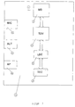
- FIG. 4 shows the block diagram of the control unit 2.
- This consists of a telephone modem 35 for the input and output of data from and in the telephone switching network, an interface bus 485 14 and one Interface bus RS 232 15, via which the connection to the components of the the head unit 6 or to different data processing devices is, as well as from a control processor 36 that the entire performs the necessary system process.
- the control device 2 a subsystem 37 that inserts images and displays the screen generated, which are transmitted to the network users via the MATV / SMATV network 5 become.
- This subsystem 37 consists of a secondary processor 38 which the entire configuration is created and the operation of the subsystem is controlled, this in response to instructions from the control processor 36, from a memory device 39, which stores video screen displays, and from an on screen Display circuitry (OSD) 40 which displays the video screens at its output in RGB format.
- OSD on screen Display circuitry
- an RGB-PAL converter 42 is arranged, a modulator 43 and an up-converter 57, of the signals in RGB format generated by the subsystem 37 are converted into signals in PAL standard format, and in a high frequency (RF) channel are arranged for their distribution over the MATV / SMATV network.
- RF high frequency
- the control unit 2 also has connections 4 for connection to the MATV / SMATV network 5, connections 7 for connection to the connecting bus 485 with the head unit 6 and the communication center 1, Ports 9 for access to the telephone switching network and ports 10 of type RS 232 for data processing equipment with data and outputs.
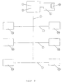
- Figure 5 shows the block diagram of the user terminal 3, which as shown Data voice modem 12, a data voice terminal 44 and an RTC adapter 45 having. It also has connections 9 for connection to a telephone device 8 and to the telephone network as well as connections 4 for connection to the MATV-SMATV network 5.
- the data language terminal 44 has a microprocessor, the hardware components have been added that are necessary to complete the procedures in the DECT standard to perform.
- This data voice terminal 44 manages the connections between the user terminal 3 and the communication center 1 and performs the control of RTC adapter 45 and the data voice modem 12 through to the functions of the user terminal 3, such as (voice) connections to keep using the electronic door intercom, in particular to open the door, commands entered via the keyboard of the terminal 3 be fed to the head unit and the electronic door intercom configure.
- the RTC adapter circuit 45 which is shown in FIG. 6, has a circuit DAA 46, a circuit SLIC 47, a DTMF detector 48, two relays 49 and an oscillator 50.
- the adapter circuit 45 provides the connection element 9 shows a connection between the telephone switching network and data speech terminal 44 ago.
- the MATV / SMATV network 5 is with this terminal 44 via the data voice modem 12 connected.
- the task of the adapter 45 is that various connections made by a conventional telephone line or coming from an internal telephone line, via the data voice modem 12 to lead the coaxial cable 41 (see Figure 1). It is designed in such a way to forward that internal or external connections, any connections hold, insert DTMF tones to select desired functions, for example the selection of the connection type (internal or external Connection), activation of a waiting state, opening the door and sending of data.
- the circuit DAA 46 adds the DTMF tones from the data voice terminal 44 come into the conventional telephone line or connection, extracted DTMF tones that an operator hears from their phone over the phone line has transmitted the data voice terminal 44.
- This device also performs the Function off to keep connections, since DAA 46 in the "removed” state Telephone receiver "remains if a internal connection that is to be established is notified.
- the elements or Connections that control this circuit are EN_HOOK, which function the Realized "handset off hook” and DET_RING, which informs that connections from the switching network are pending.
- the adapter 45 also has a circuit SLIC 47, the function of which is simulate a phone line to which the phone is connected, if there is an internal connection via the coaxial cable. This arrangement generates the RING signal that is required for the phone to ringtones outputs, as well as the voltage of the line that the operation of the terminal allows.
- the main control lines that control the SLIC circuit are DET_HOOK, which is used to record the "handset off hook" status of the User terminal is used, and EN_RING, which is used to transmit enable a ringing signal to the user terminal.
- DTMF detector 48 Another circuit that is included in adapter 45 is a DTMF detector 48, which detects the sounds that the user has in the case of an external Introduces connection over the telephone switching network, or that of the user introduces SLIC 47 in the case of an internal connection.
- the captured information is input to the data voice terminal 44 to be there to be analyzed so that the user can use his keyboard to use his telephone 8 to establish or forward the connections, to keep waiting the door of the condominium to open or send any command to the head unit 6.
- FIG. 7 shows another embodiment of the user terminal 3.
- This embodiment represents the electronic door control device 51.
- This device 51 has a data speech modem 12, a data speech terminal 44, a keyboard 52 for entering data, and an optical display device LCD 53 for displaying messages , a loudspeaker 54, a microphone 55 and a door opening device 56.
- the electronic door operating device 51 manages or controls communication and the opening of the door.
- the system according to the invention is designed in such a way that (voice and / or data) connections, for example between system components 1, 2, 3, 6, 8, 9, 51, 60, 61, ... etc. are produced in a bidirectional form, and that the entire operation of the communication connections with all system components is made possible.
- the system enables user rights to be managed. It also enables the connection of any end devices via the user end device 3. Terminal devices can be connected to the antenna cable (in particular to the coaxial cable) 5 via any channels (RF, coaxial cable, cable with pairs of conductors, etc.), the respective interfaces being provided.
- system according to the invention has the possibility of Connection to public networks, both from system terminals and from Management devices.
Applications Claiming Priority (7)
| Application Number | Priority Date | Filing Date | Title |
|---|---|---|---|
| ES200002050 | 2000-08-02 | ||
| ES200002050A ES2177412B1 (es) | 2000-08-04 | 2000-08-04 | Sistema de comunicacion aplicable a redes de smatv. |
| ES200002048A ES2177410B1 (es) | 2000-08-04 | 2000-08-04 | Sistema de comunicacion aplicable a sistemas de recepcion de radio y/o tv. |
| ES200002047A ES2176096B1 (es) | 2000-08-04 | 2000-08-04 | Sistema de recepcion y de tratamiento de señales. |
| ES200002047 | 2000-08-04 | ||
| ES200002048 | 2000-08-04 | ||
| DE10121292A DE10121292A1 (de) | 2000-08-04 | 2001-05-02 | Kommunikationssystem |
Publications (3)
| Publication Number | Publication Date |
|---|---|
| EP1182872A2 true EP1182872A2 (fr) | 2002-02-27 |
| EP1182872A3 EP1182872A3 (fr) | 2003-04-02 |
| EP1182872B1 EP1182872B1 (fr) | 2009-07-15 |
Family
ID=27437964
Family Applications (1)
| Application Number | Title | Priority Date | Filing Date |
|---|---|---|---|
| EP01118953A Expired - Lifetime EP1182872B1 (fr) | 2000-08-04 | 2001-08-04 | Système de communication |
Country Status (3)
| Country | Link |
|---|---|
| EP (1) | EP1182872B1 (fr) |
| DE (2) | DE10121292A1 (fr) |
| ES (2) | ES2176096B1 (fr) |
Cited By (1)
| Publication number | Priority date | Publication date | Assignee | Title |
|---|---|---|---|---|
| EP2367321A1 (fr) | 2010-03-05 | 2011-09-21 | Televés, S.A. | Système de communication |
Families Citing this family (2)
| Publication number | Priority date | Publication date | Assignee | Title |
|---|---|---|---|---|
| DE102005008125A1 (de) * | 2005-02-21 | 2006-09-07 | FTA Communications Technologies S.à.r.l. | LNB-Empfangseinrichtung |
| CN207355679U (zh) * | 2017-03-06 | 2018-05-15 | 龚小华 | 一种美发器 |
Citations (3)
| Publication number | Priority date | Publication date | Assignee | Title |
|---|---|---|---|---|
| DE2951544A1 (de) * | 1979-12-21 | 1981-07-23 | Hermann 8500 Nürnberg Leber | Integrierte kommunikationsanlage |
| DE19811826A1 (de) * | 1997-06-26 | 1999-02-04 | Samsung Electronics Co Ltd | Vorrichtung und Verfahren für das Bereitstellen eines PC-Kommunikations- und Internet-Dienstes unter Verwendung einer Set-Top-Box |
| US6038425A (en) * | 1998-08-03 | 2000-03-14 | Jeffrey; Ross A. | Audio/video signal redistribution system |
Family Cites Families (2)
| Publication number | Priority date | Publication date | Assignee | Title |
|---|---|---|---|---|
| ATE2471T1 (de) * | 1978-06-30 | 1983-03-15 | Telease Incorporated | Verfahren und system der kostenrechnung fuer abonnement fuer und zugang zum fernsehen. |
| WO2000030354A1 (fr) * | 1998-11-13 | 2000-05-25 | Discovery Communications, Inc. | Classement de programmes numeriques de diffusion |
-
2000
- 2000-08-04 ES ES200002047A patent/ES2176096B1/es not_active Expired - Fee Related
-
2001
- 2001-05-02 DE DE10121292A patent/DE10121292A1/de not_active Ceased
- 2001-08-04 EP EP01118953A patent/EP1182872B1/fr not_active Expired - Lifetime
- 2001-08-04 ES ES01118953T patent/ES2332986T3/es not_active Expired - Lifetime
- 2001-08-04 DE DE50114986T patent/DE50114986D1/de not_active Expired - Lifetime
Patent Citations (3)
| Publication number | Priority date | Publication date | Assignee | Title |
|---|---|---|---|---|
| DE2951544A1 (de) * | 1979-12-21 | 1981-07-23 | Hermann 8500 Nürnberg Leber | Integrierte kommunikationsanlage |
| DE19811826A1 (de) * | 1997-06-26 | 1999-02-04 | Samsung Electronics Co Ltd | Vorrichtung und Verfahren für das Bereitstellen eines PC-Kommunikations- und Internet-Dienstes unter Verwendung einer Set-Top-Box |
| US6038425A (en) * | 1998-08-03 | 2000-03-14 | Jeffrey; Ross A. | Audio/video signal redistribution system |
Cited By (1)
| Publication number | Priority date | Publication date | Assignee | Title |
|---|---|---|---|---|
| EP2367321A1 (fr) | 2010-03-05 | 2011-09-21 | Televés, S.A. | Système de communication |
Also Published As
| Publication number | Publication date |
|---|---|
| DE50114986D1 (de) | 2009-08-27 |
| DE10121292A1 (de) | 2002-11-07 |
| ES2332986T3 (es) | 2010-02-16 |
| ES2176096B1 (es) | 2004-01-16 |
| ES2176096A1 (es) | 2002-11-16 |
| EP1182872B1 (fr) | 2009-07-15 |
| EP1182872A3 (fr) | 2003-04-02 |
Similar Documents
| Publication | Publication Date | Title |
|---|---|---|
| DE69916623T2 (de) | Audio/video wiederverteilungssystem | |
| DE69721051T2 (de) | System für bürobreitbandkommunikation unter verwendung von verdrillten telefonzweidrahtleitungen | |
| DE60022392T2 (de) | Verfahren und gerät zum bereitstellen von sprach/vereinigten nachrichtendiensten(ums) mit kabelfernsehendgeräten | |
| DE60311139T2 (de) | Addressierbare telefonsteckdose und datennetz mit solchen telefonsteckdosen | |
| DE19741241A1 (de) | Bildtelefongerät, Verfahren und System für Ton- und Bildkonferenzschaltung und Telefonie | |
| DE19802226A1 (de) | Multimedia-Eingabe-/Steuervorrichtung und Verfahren für die Multimediakommunikation | |
| DE102006058540A1 (de) | Telefonsystem mit Türklingel | |
| DE69914607T2 (de) | Verfahren und gerät für datenkommunikation | |
| AT15530U1 (de) | Multikanal-videogegensprechanlagensystem mit zugang zu fortschrittlichen digitalen diensten | |
| CH651162A5 (de) | Leitergebundene bild- und tonsignaluebertragungsanlage mit videophonie. | |
| DE10333818A1 (de) | Verfahren und Vorrichtung zur Durchführung eines Personal-Führungs-Schutz-Systems | |
| EP1182872B1 (fr) | Système de communication | |
| EP0208959A1 (fr) | Système de communication | |
| WO2003017576A2 (fr) | Procede et systeme de communication dans un reseau de communication sans fil | |
| DE10116860A1 (de) | System zum Empfang und zur Verarbeitung von Signalen | |
| DE3215261C2 (fr) | ||
| DE19744056A1 (de) | Videotelefonvorrichtung, Verfahren und System für Drahtleitungs-Audio- und Videokonferenzen und Telefongespräche | |
| DE19751870A1 (de) | Gerät, Verfahren und System für drahtlose Ton- und Bildkonferenzschaltung und Telefonie | |
| DE10116384A1 (de) | Kommunikationssystem | |
| DE10116549A1 (de) | Fernsprechsystem | |
| DE10116385A1 (de) | Kommunikationssystem | |
| DE19629773C1 (de) | System zur Wiedergabe von Ton- und/oder Videosignalen und zur Steuerung von elektronischen Geräten in verschiedenen Räumen einer Wohnung oder in einem Haus | |
| DE4221439A1 (de) | Telekommunikationseinrichtung mit einer Anordnung zur Speicherung und Wiedergabe einer hinterlegten Nachricht | |
| DE19735384A1 (de) | Verfahren, System und Vorrichtungen zur Funkanbindung mehrerer Endgeräte über eine Basisstation an eine Schnittstelle eines Telefon- oder Datennetzes | |
| DE202012012542U1 (de) | Türsprechanlage |
Legal Events
| Date | Code | Title | Description |
|---|---|---|---|
| PUAI | Public reference made under article 153(3) epc to a published international application that has entered the european phase |
Free format text: ORIGINAL CODE: 0009012 |
|
| AK | Designated contracting states |
Kind code of ref document: A2 Designated state(s): AT BE CH CY DE DK ES FI FR GB GR IE IT LI LU MC NL PT SE TR |
|
| AX | Request for extension of the european patent |
Free format text: AL;LT;LV;MK;RO;SI |
|
| RIN1 | Information on inventor provided before grant (corrected) |
Inventor name: FERNANDEZ CARNERO, JOSE LUIS, C/O TELEVES, S.A. Inventor name: BARREIRO TABOADA, CARLOS, C/O TELEVES, S.A. Inventor name: DE UNA PINERO, RAFAEL, C/O TELEVES, S.A. |
|
| PUAL | Search report despatched |
Free format text: ORIGINAL CODE: 0009013 |
|
| AK | Designated contracting states |
Kind code of ref document: A3 Designated state(s): AT BE CH CY DE DK ES FI FR GB GR IE IT LI LU MC NL PT SE TR |
|
| AX | Request for extension of the european patent |
Extension state: AL LT LV MK RO SI |
|
| 17P | Request for examination filed |
Effective date: 20031002 |
|
| AKX | Designation fees paid |
Designated state(s): DE ES FR GB IT PT |
|
| GRAP | Despatch of communication of intention to grant a patent |
Free format text: ORIGINAL CODE: EPIDOSNIGR1 |
|
| GRAS | Grant fee paid |
Free format text: ORIGINAL CODE: EPIDOSNIGR3 |
|
| GRAA | (expected) grant |
Free format text: ORIGINAL CODE: 0009210 |
|
| AK | Designated contracting states |
Kind code of ref document: B1 Designated state(s): DE ES FR GB IT PT |
|
| REG | Reference to a national code |
Ref country code: GB Ref legal event code: FG4D Free format text: NOT ENGLISH |
|
| REF | Corresponds to: |
Ref document number: 50114986 Country of ref document: DE Date of ref document: 20090827 Kind code of ref document: P |
|
| REG | Reference to a national code |
Ref country code: PT Ref legal event code: SC4A Free format text: AVAILABILITY OF NATIONAL TRANSLATION Effective date: 20091113 |
|
| REG | Reference to a national code |
Ref country code: ES Ref legal event code: FG2A Ref document number: 2332986 Country of ref document: ES Kind code of ref document: T3 |
|
| PLBE | No opposition filed within time limit |
Free format text: ORIGINAL CODE: 0009261 |
|
| STAA | Information on the status of an ep patent application or granted ep patent |
Free format text: STATUS: NO OPPOSITION FILED WITHIN TIME LIMIT |
|
| 26N | No opposition filed |
Effective date: 20100416 |
|
| PGFP | Annual fee paid to national office [announced via postgrant information from national office to epo] |
Ref country code: PT Payment date: 20130307 Year of fee payment: 13 |
|
| PGFP | Annual fee paid to national office [announced via postgrant information from national office to epo] |
Ref country code: DE Payment date: 20130831 Year of fee payment: 13 |
|
| PGFP | Annual fee paid to national office [announced via postgrant information from national office to epo] |
Ref country code: GB Payment date: 20130823 Year of fee payment: 13 Ref country code: FR Payment date: 20130820 Year of fee payment: 13 |
|
| PGFP | Annual fee paid to national office [announced via postgrant information from national office to epo] |
Ref country code: IT Payment date: 20130823 Year of fee payment: 13 |
|
| REG | Reference to a national code |
Ref country code: PT Ref legal event code: MM4A Free format text: LAPSE DUE TO NON-PAYMENT OF FEES Effective date: 20150204 |
|
| REG | Reference to a national code |
Ref country code: DE Ref legal event code: R119 Ref document number: 50114986 Country of ref document: DE |
|
| GBPC | Gb: european patent ceased through non-payment of renewal fee |
Effective date: 20140804 |
|
| PG25 | Lapsed in a contracting state [announced via postgrant information from national office to epo] |
Ref country code: PT Free format text: LAPSE BECAUSE OF NON-PAYMENT OF DUE FEES Effective date: 20150204 Ref country code: IT Free format text: LAPSE BECAUSE OF NON-PAYMENT OF DUE FEES Effective date: 20140804 |
|
| REG | Reference to a national code |
Ref country code: DE Ref legal event code: R119 Ref document number: 50114986 Country of ref document: DE Effective date: 20150303 |
|
| REG | Reference to a national code |
Ref country code: FR Ref legal event code: ST Effective date: 20150430 |
|
| PG25 | Lapsed in a contracting state [announced via postgrant information from national office to epo] |
Ref country code: DE Free format text: LAPSE BECAUSE OF NON-PAYMENT OF DUE FEES Effective date: 20150303 Ref country code: GB Free format text: LAPSE BECAUSE OF NON-PAYMENT OF DUE FEES Effective date: 20140804 |
|
| PG25 | Lapsed in a contracting state [announced via postgrant information from national office to epo] |
Ref country code: FR Free format text: LAPSE BECAUSE OF NON-PAYMENT OF DUE FEES Effective date: 20140901 |
|
| PGFP | Annual fee paid to national office [announced via postgrant information from national office to epo] |
Ref country code: ES Payment date: 20160727 Year of fee payment: 16 |
|
| REG | Reference to a national code |
Ref country code: ES Ref legal event code: FD2A Effective date: 20181029 |
|
| PG25 | Lapsed in a contracting state [announced via postgrant information from national office to epo] |
Ref country code: ES Free format text: LAPSE BECAUSE OF NON-PAYMENT OF DUE FEES Effective date: 20170805 |