EP1182872A2 - Communication system - Google Patents
Communication system Download PDFInfo
- Publication number
- EP1182872A2 EP1182872A2 EP01118953A EP01118953A EP1182872A2 EP 1182872 A2 EP1182872 A2 EP 1182872A2 EP 01118953 A EP01118953 A EP 01118953A EP 01118953 A EP01118953 A EP 01118953A EP 1182872 A2 EP1182872 A2 EP 1182872A2
- Authority
- EP
- European Patent Office
- Prior art keywords
- communication system
- data
- communication
- terminal
- unit
- Prior art date
- Legal status (The legal status is an assumption and is not a legal conclusion. Google has not performed a legal analysis and makes no representation as to the accuracy of the status listed.)
- Granted
Links
Images


Classifications
-
- H—ELECTRICITY
- H04—ELECTRIC COMMUNICATION TECHNIQUE
- H04N—PICTORIAL COMMUNICATION, e.g. TELEVISION
- H04N7/00—Television systems
- H04N7/10—Adaptations for transmission by electrical cable
- H04N7/106—Adaptations for transmission by electrical cable for domestic distribution
Definitions
- the invention relates to a communication system according to the preamble of Claim 1.
- MATV / SMATV systems are already known, that is to say common antenna systems, the television signals from terrestrial transmitters or satellites received and lead to various system components that users assigned to the system.
- These systems essentially consist of a unit that receives the television signals from terrestrial transmitters or satellites, from a head unit, which adapts and amplifies the received signals, and from a distribution network, through which the signals to the system components transferred that are assigned to the system users.
- the number of users of these MATV / SMATV systems is at most a few One hundred limited; the signals that are distributed in the systems are in never generated in the respective network.
- a message system is already known from German patent application DE 3524094 A1 known, which is connected to a common antenna (30).
- the known system has an antenna cable (26) to which receiving stations (38) and a so-called exterior door control panel (10) is connected; it enables connections between the outer door control panel (10) and each exactly one receiving station (38).
- Exactly one analog channel is used for this, which is the same for all apartments that are connected to the system.
- the Allocation of this analog channel is controlled by a control center Is assigned to receiving stations, the control taking place in such a way that there is only one voice connection at a time.
- the object of the invention based on specifying a communication system of the type mentioned at the beginning, that allows further uses.
- the invention has a number of advantages.
- a first embodiment of the invention is advantageous Communication system designed in such a way that a central control unit Communication connections between at least two user terminals controls; the central control unit also controls communication connections, on which at least one user terminal and / or at least one other system unit and / or another communication system is involved.
- the function of the central control unit can, for example also by a user terminal and / or another system unit be exercised.
- the system according to the invention thus combines the advantages of a common antenna (MATV / SMATV) system with the advantages of a communication system, such as a private branch exchange for voice, Images and / or data. Among other things, it enables voice and data connections on the one hand between apartments of a residential complex with each other as well as at least one apartment and one gatekeeper or door communication unit on the other hand.
- a common antenna MATV / SMATV
- the communication system according to the invention is also with a connectable to another communication system, especially with a public one Fixed and / or mobile telecommunications network (cordless or "wireless" systems).
- the communication system is a signal processing unit (Head unit) has the signals that go beyond the minimum an antenna can be received, edited.
- the signal processing unit is controllable according to the invention, for example, by a user terminal.
- the System users thus get the advantageous option of a plurality of television channels entered into the system Select TV channels.
- the communication system according to the invention can also be done by a non-system unit or by external system administrators (Installers, specialists such as maintenance personnel, ...) configure or wait without these having to go to the location of the system.
- Another embodiment of the communication system according to the invention is characterized in that the communication system is configured in this way is that the communication links using digital signals to be controlled. This allows a variety of functions such as the administration of authorizations of the different system users implement in a comparatively simple manner.
- the signal processing unit has a memory is assigned, which contains service data with which services within or outside the communication system, in particular with a time delay (not in real time).
- a system unit e.g. user terminal, control device, Component of the signal processing unit
- Play a saved movie activate the operation of pre-programmed Facilities, visualization of images, query of Databases, etc.
- the memory is preferably not only for system units, but also for at least one further (external) communication system, in particular for one public landline or mobile telecommunications network, accessible.
- the memory is a hard disk or a removable storage medium such as a CD-ROM or a floppy disk.
- the user terminal is a telephone terminal and / or a data terminal, in particular a data processing device is.
- This enables the implementation of interactive services such as Internet, voice, data, video, and operations control services in the system.
- TDMA time division multiplexing
- Data language base This component is central because it is all internal connections (between user terminals and door system) processed or mediated. It is located in the communication center.
- Data voice terminal This component processes connections on the terminal side the user. It is located in the user terminal in the apartment of the user.
- Data language modem This component is essential for the functionality of the system. It is located on the one hand at the system headquarters and on the other other in user terminals and enables the establishment of connections between the system center and user terminals. In the communication system according to the invention works the data voice modem in the frequencies of the Return channel, while conventional DECT MODEMs in the frequency of 1.9 GHz work.
- RTC adapter This component is the interface between the user terminal and the telephone switching network and enables internal connections from a user's terminal to another terminal of the MATV / SMATV network; this component also enables connections from the door intercom to receive and outgoing and incoming connections to establish over the telephone switching network.
- the system according to the invention simultaneously enables at least one internal one Connection between people or facilities in the residential units among themselves and also connections between the door system and the Units.
- MATV / SMATV networks be enabled for remote operation control, parameters of the head units (6 in Figure 1) by system administrators and / or users of these networks an RS232 connection, over the telephone switching network or over the MATV / SMATV network can be controlled.
- Operation control unit This component is located in the communication center and edited the data by the data base received and converts this data into a for further processing suitable format.
- Control processor This component processes the operational control data of the head units and is located in the control device (2 in FIG. 1).
- This component is located in the control device (2nd in Figure 1) and enables the initiation of the operational control or signaling data the head unit via the telephone network.
- RS 232 interface bus This component enables input and output the data of the operational control or signaling data of the head unit a local computer (PC). It is located in the control unit and in the Communications center.
- PC local computer
- Interface bus 485 This component enables connections between the Control device (2 in Figure 1) and the devices that make up the head unit of the MATV / SMATV network integrated. It is located in the control device (2 in Figure 1) and in the communication center.
- the system according to the invention which is designed in this way, enables an adjustment to the users and administrators of the MATV / SMATV network and Maintaining the network on site without the need to travel as this task directly from any - authorized - user terminal or on site of the network administrator either by means of telephony equipment or via the Internet can be done.
- Another advantage of the system according to the invention is that To provide a visual information system to MATV / SMATV networks that consists of one or more television channels in the control device (2 in Figure 1) are formed, their generation and modification can take place via a telecommunications switching network, for example via a local computer (e.g. PC) via an RS 232 interface or via a User terminal.
- a local computer e.g. PC
- RS 232 interface e.g. RS 232 interface
- control processor realized in the control device (2 in Figure 1) and in an image generation system is arranged.
- Image generation system This system generates screen displays that over the SMATV / MATV network are transmitted. It consists of a control processor, a storage device, a subsystem that inserts images RG / PAL converter, a modulator and an output up converter. The image generation system is arranged in the control device (2 in FIG. 1).
- the system according to the invention thus enables the transmission of images User terminals over the telephone switching network, over a local one Computer (PC) or via a user terminal, as already described.
- PC Computer
- the communication system according to the invention can be a storage device which enable the acquisition and storage of images.
- Another advantage of the communication system according to the invention is in that data transfers between users of the MATV / SMATV network and the control device (2 in FIG. 1). at the same time enables the processing of this data by means of the data processor the system has. This enables different facilities, that can be connected to the MATV / SMATV network by different users over the telephone switching network, over a local computer or can be controlled via a user terminal.
- the communication system according to the invention a communication center 1, which has the function of the central control and is also shown in Figure 2, a control unit 2 ( Figure 4) and several User terminals 3 (Figure 5).
- the user terminals 3 are preferred Telephone devices or units that have a telephone device 8.
- On The user terminal forms the central communication terminal 51 (FIG. 7).
- the mentioned system components 1, 2, 3 and 51 are via connecting elements (Plug) 4 connected to a MATV / SMATV network 5 via connecting cable 41.
- the MATV / SMATV network consists of exactly one antenna cable 5, in particular from a coaxial cable, like this is also shown in Figure 8.
- the system according to the invention is designed in such a way that it is Communication connections between the central communication terminal 51 on the one hand and in each case one or more user terminals 3 (e.g. 301, 302, ... or 30n; Figure 8) on the other hand also communication connections between two and more user terminals 3 (e.g. 301, 302, ... or 30n; figure 8) manufactures. So in the communication system according to the invention for example a communication connection, in particular a telephone connection between the user terminal 301 and the user terminal 302 manufactured.
- the communication system according to the invention thus also offers the Functions of a telecommunications or private branch exchange.
- the system also controls communication connections on which another System unit (e.g. alarm sensors, data storage 58, etc.) and a user terminal 3 is involved.
- another System unit e.g. alarm sensors, data storage 58, etc.
- a user terminal 3 is involved.
- the control unit 2 is also with the communication center 1 and with various Units to which the head unit 6 of the MATV / SMATV system heard, via communication elements 7 by means of a connecting bus 71 connected.
- the user terminal 3 is with a telephone device 8, with a further communication system, in particular with a telephone switching system, via connecting elements or connections 9 by means of cables 91 and to at least one television 60 and / or a radio 61 by means of Cable 91 connected.
- the system according to the invention can be used with another Communication system also via the control center 1 or the control unit 2 be connected.
- the head unit 6 is a signal processing unit, the signals that over the at least one antenna are received, processed.
- the signal processing or head unit 6 is in the communication system according to the invention of system units (e.g. 1, 2, 3, 51, 58) and / or of one further communication system, in particular controllable from a telecommunications network.
- system units e.g. 1, 2, 3, 51, 58
- one further communication system in particular controllable from a telecommunications network.
- a memory 58 is assigned to the signal processing unit 6 and contains the service data contains services with which inside or outside the Communication system, in particular with a time delay (not in real time) become.
- a system unit e.g. user terminal, Control device, component of the signal processing unit
- the memory 58 is for system units and / or for at least one external one Communication system, especially for a fixed or mobile telecommunications network, accessible.
- the data stored in memory 58 is in System units and / or in at least one external communication system, especially transferable to a fixed or mobile telecommunications network.
- the memory 58 is, in particular, a hard disk, a CD-ROM or a floppy disk.
- more than one system unit can access the at the same time Memory 58 have to point to the same or different data contained in the Memory 58 are stored to access and / or to write data.
- the communication system according to the invention can continue in this way be designed so that information (operational information) between the Signal processing unit 6 and at least one user terminal 3 uni- or be transmitted bidirectionally.
- This information denotes operating states the signal processing unit 6 and / or the mode of operation thereof Unit 6.
- the user terminal 3 forms signals that indicate operating states and / or act on the functioning of the unit 6.
- This signal processing unit is a known head unit, for example Has amplifiers, converters, processors, transmodulators, etc.
- the head or signal processing unit forms a parameter selection menu and transmits this to a user terminal that the menu requests, for example with the intention of changing the parameters of the Change head unit.
- a user terminal and using the menu to transmit the information to the head unit that the A specific channel must be changed.
- Other examples of that Parameters are output voltage, audio and video level and change of one Receiving channel.
- Another operating information transmitted by a user terminal 3 is a software file that shows a modified operation of the head unit 6 Are defined.
- a person who has to manage the system can partially or completely control the operation of the head unit.
- the user terminals 3 and the unit 51 can have user authorizations be assigned; this includes new user permissions, the assignment of services to users, the blocking of services due to non-payment, system and service shutdowns, etc.
- the communication system can also be designed in such a way that Information (operational information) between the signal processing unit 6 and at least one other communication system unidirectional or bidirectional are transmitted, the information operating states of the signal processing unit 6 and / or the operation of this unit 6.
- the other communication system in particular a telephone network, forms Signals that relate to operating states and / or the functioning of the unit 6 act.
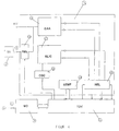
- Figure 2 shows a block diagram of the communication center 1.
- the communication center 1 consists of a data language base 11, a data voice modem 12, an operation control unit 13, from an interface bus 485 14 and an interface bus RS232 15.
- connection elements 4 for connection to the MATV / SMATV network 5
- connecting elements 7 for connection to the control unit 2 and various units in the head unit 6
- connecting elements 10 for connecting units that process input data and Form output data on.
- the data language base 11 consists of a microprocessor, for example works according to the DECT communication standard, and from one Memory that stores the operating software of the microprocessor.
- the data voice modem 12 consists of an input / output / coupling element 16, an input bandpass filter 17 and one Output bandpass filter 18, which is the input-output stage of the device form.
- the input and output signals are switched by means of a switching arrangement 19 separated.
- the data voice modem 12 has a first one for processing the input signal Mixing circuit 20, the function of which is to convert the input signal into a Intermediate frequency (110 MHz) implement, the output signal of a stage the first intermediate frequency is supplied, which consists of an amplifier 21 and a SAW filter 22, wherein a second mixer circuit 23, the signal in converts a second intermediate frequency (9.996 MHz). Then the signal is in entered a second stage of the intermediate frequency, which consists of two bandpasses 24 and 25 and amplifiers 26 and 27.
- the signal is then fed to a quadrature demodulator 28 from which signal (GFSK Gaucian Frequency Shiftling Keying) data is extracted which are then supplied to the data language base 11.
- the mixed converter signals are generated by local oscillators 29 and 30 by PLL circuits 32 and 31 can be controlled.
- the output signal is generated from the data from the data language base 11 originate.
- the signal is frequency modulated and an output mixer 33 fed and then amplified in an output amplifier 34 and via the Switching arrangement 19 fed to the output.
- the operation control unit 13 consists of a microprocessor and a Storage device that stores the operating software of the microprocessor.
- the microprocessor manages the RS 2332 and 485 communication buses.
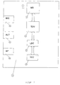
- FIG. 4 shows the block diagram of the control unit 2.
- This consists of a telephone modem 35 for the input and output of data from and in the telephone switching network, an interface bus 485 14 and one Interface bus RS 232 15, via which the connection to the components of the the head unit 6 or to different data processing devices is, as well as from a control processor 36 that the entire performs the necessary system process.
- the control device 2 a subsystem 37 that inserts images and displays the screen generated, which are transmitted to the network users via the MATV / SMATV network 5 become.
- This subsystem 37 consists of a secondary processor 38 which the entire configuration is created and the operation of the subsystem is controlled, this in response to instructions from the control processor 36, from a memory device 39, which stores video screen displays, and from an on screen Display circuitry (OSD) 40 which displays the video screens at its output in RGB format.
- OSD on screen Display circuitry
- an RGB-PAL converter 42 is arranged, a modulator 43 and an up-converter 57, of the signals in RGB format generated by the subsystem 37 are converted into signals in PAL standard format, and in a high frequency (RF) channel are arranged for their distribution over the MATV / SMATV network.
- RF high frequency
- the control unit 2 also has connections 4 for connection to the MATV / SMATV network 5, connections 7 for connection to the connecting bus 485 with the head unit 6 and the communication center 1, Ports 9 for access to the telephone switching network and ports 10 of type RS 232 for data processing equipment with data and outputs.
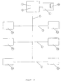
- Figure 5 shows the block diagram of the user terminal 3, which as shown Data voice modem 12, a data voice terminal 44 and an RTC adapter 45 having. It also has connections 9 for connection to a telephone device 8 and to the telephone network as well as connections 4 for connection to the MATV-SMATV network 5.
- the data language terminal 44 has a microprocessor, the hardware components have been added that are necessary to complete the procedures in the DECT standard to perform.
- This data voice terminal 44 manages the connections between the user terminal 3 and the communication center 1 and performs the control of RTC adapter 45 and the data voice modem 12 through to the functions of the user terminal 3, such as (voice) connections to keep using the electronic door intercom, in particular to open the door, commands entered via the keyboard of the terminal 3 be fed to the head unit and the electronic door intercom configure.
- the RTC adapter circuit 45 which is shown in FIG. 6, has a circuit DAA 46, a circuit SLIC 47, a DTMF detector 48, two relays 49 and an oscillator 50.
- the adapter circuit 45 provides the connection element 9 shows a connection between the telephone switching network and data speech terminal 44 ago.
- the MATV / SMATV network 5 is with this terminal 44 via the data voice modem 12 connected.
- the task of the adapter 45 is that various connections made by a conventional telephone line or coming from an internal telephone line, via the data voice modem 12 to lead the coaxial cable 41 (see Figure 1). It is designed in such a way to forward that internal or external connections, any connections hold, insert DTMF tones to select desired functions, for example the selection of the connection type (internal or external Connection), activation of a waiting state, opening the door and sending of data.
- the circuit DAA 46 adds the DTMF tones from the data voice terminal 44 come into the conventional telephone line or connection, extracted DTMF tones that an operator hears from their phone over the phone line has transmitted the data voice terminal 44.
- This device also performs the Function off to keep connections, since DAA 46 in the "removed” state Telephone receiver "remains if a internal connection that is to be established is notified.
- the elements or Connections that control this circuit are EN_HOOK, which function the Realized "handset off hook” and DET_RING, which informs that connections from the switching network are pending.
- the adapter 45 also has a circuit SLIC 47, the function of which is simulate a phone line to which the phone is connected, if there is an internal connection via the coaxial cable. This arrangement generates the RING signal that is required for the phone to ringtones outputs, as well as the voltage of the line that the operation of the terminal allows.
- the main control lines that control the SLIC circuit are DET_HOOK, which is used to record the "handset off hook" status of the User terminal is used, and EN_RING, which is used to transmit enable a ringing signal to the user terminal.
- DTMF detector 48 Another circuit that is included in adapter 45 is a DTMF detector 48, which detects the sounds that the user has in the case of an external Introduces connection over the telephone switching network, or that of the user introduces SLIC 47 in the case of an internal connection.
- the captured information is input to the data voice terminal 44 to be there to be analyzed so that the user can use his keyboard to use his telephone 8 to establish or forward the connections, to keep waiting the door of the condominium to open or send any command to the head unit 6.
- FIG. 7 shows another embodiment of the user terminal 3.
- This embodiment represents the electronic door control device 51.
- This device 51 has a data speech modem 12, a data speech terminal 44, a keyboard 52 for entering data, and an optical display device LCD 53 for displaying messages , a loudspeaker 54, a microphone 55 and a door opening device 56.
- the electronic door operating device 51 manages or controls communication and the opening of the door.
- the system according to the invention is designed in such a way that (voice and / or data) connections, for example between system components 1, 2, 3, 6, 8, 9, 51, 60, 61, ... etc. are produced in a bidirectional form, and that the entire operation of the communication connections with all system components is made possible.
- the system enables user rights to be managed. It also enables the connection of any end devices via the user end device 3. Terminal devices can be connected to the antenna cable (in particular to the coaxial cable) 5 via any channels (RF, coaxial cable, cable with pairs of conductors, etc.), the respective interfaces being provided.
- system according to the invention has the possibility of Connection to public networks, both from system terminals and from Management devices.
Abstract
Description
Die Erfindung betrifft ein Kommunikationssystem nach dem Oberbegriff des
Anspruchs 1.The invention relates to a communication system according to the preamble of
Es sind bereits sogenannte MATV/SMATV-Systeme bekannt, das heißt Gemeinschaftsantennensysteme, die Fernsehsignale terrestrischer Sender oder Satelliten empfangen und zu verschiedenen Systemkomponenten führen, die Benutzern des Systems zugeordnet sind. Diese Systeme bestehen im wesentlichen aus einer Einheit, die die Fernsehsignale terrestrischer Sender oder Satelliten empfängt, aus einer Kopfeinheit, die die empfangenen Signale anpasst und verstärkt, und aus einem Verteilnetz, über das die Signale zu den Systemkomponenten übertragen werden, die den Systembenutzern zugeordnet sind.So-called MATV / SMATV systems are already known, that is to say common antenna systems, the television signals from terrestrial transmitters or satellites received and lead to various system components that users assigned to the system. These systems essentially consist of a unit that receives the television signals from terrestrial transmitters or satellites, from a head unit, which adapts and amplifies the received signals, and from a distribution network, through which the signals to the system components transferred that are assigned to the system users.
Die Anzahl der Benutzer dieser MATV/SMATV-Systeme ist höchstens auf einige Hundert beschränkt; die Signale, die in den Systemen verteilt werden, werden in keinem Fall in dem jeweiligen Netz generiert.The number of users of these MATV / SMATV systems is at most a few One hundred limited; the signals that are distributed in the systems are in never generated in the respective network.
Auf dem Markt ist zur Zeit eine große Zahl von Komponenten für diese Systeme verfügbar. Diese Komponenten dienen ausschließlich dem Empfang, der Anpassung und der Verteilung von Fernseh- und Radiosignalen.A large number of components for these systems are currently on the market available. These components are for reception only Adaptation and distribution of television and radio signals.
Aus der Deutschen Patentanmeldung DE 3524094 A1 ist bereits ein Nachrichtensystem bekannt, das mit einer Gemeinschaftsantenne (30) verbunden ist. Das bekannte System weist ein Antennenkabel (26) auf, an das Empfangsstationen (38) und eine sogenannte Außentürbedientafel (10) angeschlossen ist; es ermöglicht Verbindungen zwischen der Außentürbedientafel (10) und jeweils genau einer Empfangsstation (38). Hierzu wird genau ein Analogkanal verwendet, der für alle Wohnungen gleich ist, die an das System angeschlossen sind. Die Belegung dieses Analogkanals wird durch eine Zentrale gesteuert, die allen Empfangsstationen zugeordnet ist, wobei die Steuerung in der Weise erfolgt, dass jeweils nur eine Sprechverbindung besteht.A message system is already known from German patent application DE 3524094 A1 known, which is connected to a common antenna (30). The known system has an antenna cable (26) to which receiving stations (38) and a so-called exterior door control panel (10) is connected; it enables connections between the outer door control panel (10) and each exactly one receiving station (38). Exactly one analog channel is used for this, which is the same for all apartments that are connected to the system. The Allocation of this analog channel is controlled by a control center Is assigned to receiving stations, the control taking place in such a way that there is only one voice connection at a time.
Ausgehend von diesem Stand der Technik liegt der Erfindung die Aufgabe zugrunde, ein Kommunikationssystem der eingangs genannten Art anzugeben, das weitere Nutzungsmöglichkeiten erlaubt.Starting from this prior art, the object of the invention based on specifying a communication system of the type mentioned at the beginning, that allows further uses.
Diese Aufgabe wird durch ein Kommunikationssystem gelöst, das in den Ansprüchen definiert ist.This task is solved by a communication system, which in the Claims is defined.
Die Erfindung weist eine Mehrzahl von Vorteilen auf.The invention has a number of advantages.
In vorteilhafter Weise ist eine erste Ausführungsform des erfindungsgemäßen Kommunikationssystems in der Weise ausgestaltet, dass eine Zentral-Steuerungseinheit Kommunikationsverbindungen zwischen mindestens zwei Benutzerendgeräten steuert; ebenso steuert die Zentral-Steuerungseinheit Kommunikationsverbindungen, an denen mindestens ein Benutzerendgerät und/oder mindestens eine andere Systemeinheit und/oder ein weiteres Kommunikationssystem beteiligt ist. Die Funktion der Zentral-Steuerungseinheit kann beispielsweise auch durch ein Benutzerendgerät und/oder eine andere Systemeinheit ausgeübt werden.A first embodiment of the invention is advantageous Communication system designed in such a way that a central control unit Communication connections between at least two user terminals controls; the central control unit also controls communication connections, on which at least one user terminal and / or at least one other system unit and / or another communication system is involved. The function of the central control unit can, for example also by a user terminal and / or another system unit be exercised.
Das erfindungsgemäße System vereint damit die Vorteile eines Gemeinschaftsantennen(MATV/SMATV-)Systems mit den Vorteilen eines Kommunikationssystems, wie beispielsweise einer Nebenstellenanlage für Sprache, Bilder und/oder Daten. Es ermöglicht unter anderem Sprach- und Datenverbindungen einerseits zwischen Wohnungen einer Wohnanlage untereinander sowie jeweils mindestens einer Wohnung und einer Pförtner- bzw. Türkommunikationseinheit andererseits. The system according to the invention thus combines the advantages of a common antenna (MATV / SMATV) system with the advantages of a communication system, such as a private branch exchange for voice, Images and / or data. Among other things, it enables voice and data connections on the one hand between apartments of a residential complex with each other as well as at least one apartment and one gatekeeper or door communication unit on the other hand.
Das erfindungsgemäße Kommunikationssystem ist darüber hinaus mit einem weiteren Kommunikationssystem verbindbar, insbesondere mit einem öffentlichen Fest- und/oder Mobil-Fernmeldenetz (Schnurlos- bzw. "Wireless"-Systeme).The communication system according to the invention is also with a connectable to another communication system, especially with a public one Fixed and / or mobile telecommunications network (cordless or "wireless" systems).
Eine weitere Ausführungsform des erfindungsgemäßen Kommunikationssystems ist dadurch gekennzeichnet, dass das Kommunikationssystem eine Signalbearbeitungseinheit (Kopfeinheit) aufweist, die Signale, die über die mindestens eine Antenne empfangen werden, bearbeitet. Die Signalbearbeitungseinheit ist erfindungsgemäß beispielsweise von einem Benutzerendgerät steuerbar. Der Systembenutzer erhält damit in die vorteilhafte Möglichkeit, aus einer Mehrzahl von Fernsehkanälen, die in das System eingegeben werden, vorgegebene Fernsehkanäle auszuwählen. Das erfindungsgemäße Kommunikationssystem lässt sich auch von einer systemexternen Einheit bzw. von externen Systembetreuern (Installateure, Spezialisten wie Wartungspersonal, ...) konfigurieren bzw. warten, ohne dass sich diese an den Ort des Systems zu begeben hätten.Another embodiment of the communication system according to the invention is characterized in that the communication system is a signal processing unit (Head unit) has the signals that go beyond the minimum an antenna can be received, edited. The signal processing unit is controllable according to the invention, for example, by a user terminal. The System users thus get the advantageous option of a plurality of television channels entered into the system Select TV channels. The communication system according to the invention can also be done by a non-system unit or by external system administrators (Installers, specialists such as maintenance personnel, ...) configure or wait without these having to go to the location of the system.
Eine weitere Ausführungsform des erfindungsgemäßen Kommunikationssystems ist dadurch gekennzeichnet, dass das Kommunikationssystem in der Weise ausgestaltet ist, dass die Kommunikationsverbindungen mittels digitaler Signale gesteuert werden. Damit lässt sich eine Vielzahl von Funktionen wie beispielsweise die Verwaltung von Berechtigungen der verschiedenen Systembenutzer in vergleichsweise einfacher Weise implementieren.Another embodiment of the communication system according to the invention is characterized in that the communication system is configured in this way is that the communication links using digital signals to be controlled. This allows a variety of functions such as the administration of authorizations of the different system users implement in a comparatively simple manner.
Eine weitere Ausführungsform des erfindungsgemäßen Kommunikationssystems ist dadurch gekennzeichnet, dass der Signalbearbeitungseinheit ein Speicher zugeordnet ist, der Dienstleistungsdaten enthält, mit denen Dienstleistungen innerhalb oder außerhalb des Kommunikationssystems insbesondere zeitversetzt (nicht in Realzeit) erbracht werden. Damit ermöglicht das Kommunikationssystem die Generierung von Auskunftsdatenbeständen und die Realisierung von Diensten, die eine Systemeinheit (z.B. Benutzerendgerät, Steuerungseinrichtung, Komponente der Signalbearbeitungseinheit) anfordert. Beispiele sind das Abspielen eines abgespeicherten Films, die Aktivierung des Betriebs von vorprogrammierten Einrichtungen, die Visualisierung von Bildern, die Abfrage von Datenbeständen, etc.Another embodiment of the communication system according to the invention is characterized in that the signal processing unit has a memory is assigned, which contains service data with which services within or outside the communication system, in particular with a time delay (not in real time). This enables the communication system the generation of information databases and the implementation of Services that a system unit (e.g. user terminal, control device, Component of the signal processing unit) requests. These are examples Play a saved movie, activate the operation of pre-programmed Facilities, visualization of images, query of Databases, etc.
Der Speicher ist vorzugsweise nicht nur für Systemeinheiten, sondern auch für mindestens ein weiteres (externes) Kommunikationssystem, insbesondere für ein öffentliches Fest- oder Mobilfernmeldenetz, zugänglich.The memory is preferably not only for system units, but also for at least one further (external) communication system, in particular for one public landline or mobile telecommunications network, accessible.
Der Speicher ist eine Festplatte oder ein lösbares Speichermedium wie beispielsweise eine CD-ROM oder eine Diskette.The memory is a hard disk or a removable storage medium such as a CD-ROM or a floppy disk.
Schließlich ist eine weitere Ausführungsform des erfindungsgemäßen Kommunikationssystems dadurch gekennzeichnet, dass das Benutzerendgerät ein Fernsprechendgerät und/oder ein Datenendgerät, insbesondere ein Datenverarbeitungsgerät ist. Dies ermöglicht die Implementierung interaktiver Dienste wie Internet-, Sprach-, Daten-, Video- und Betriebssteuerungsdienste im System.Finally, another embodiment of the communication system according to the invention characterized in that the user terminal is a telephone terminal and / or a data terminal, in particular a data processing device is. This enables the implementation of interactive services such as Internet, voice, data, video, and operations control services in the system.
Dies wird in dem erfindungsgemäß System beispielsweise durch Zeitmultiplex (TDMA)-Verarbeitung der Informationen erzielt, die in der Türanlage bearbeitet bzw. im System übertragen werden, wobei beispielsweise der DECT-Standard verwendet wird.In the system according to the invention, this is achieved, for example, by time division multiplexing (TDMA) processing of information obtained in the door system or transmitted in the system, for example the DECT standard is used.
Zur Implementierung dieser Dienste und zur Übertragung von Sprachinformationen und Daten über das MATV/SMATV-Netz verfügt das erfindungsgemäße System über folgende Komponenten: Datensprachbasis, Datensprachendgerät, Datensprachmodem, RTC-Adapter.To implement these services and to transmit voice information and the MATV / SMATV network has data according to the invention System via the following components: data language base, data language terminal, Data voice modem, RTC adapter.
Datensprachbasis: Diese Komponente ist von zentraler Bedeutung, da sie alle internen Verbindungen (zwischen Benutzerendgeräten und Türanlage) bearbeitet bzw. vermittelt. Sie befindet sich in der Kommunikationszentrale.Data language base: This component is central because it is all internal connections (between user terminals and door system) processed or mediated. It is located in the communication center.
Datensprachendgerät: Diese Komponente bearbeitet endgeräteseitig Verbindungen der Benutzer. Sie befindet sich in dem Benutzerendgerät in der Wohnung des Benutzers. Data voice terminal: This component processes connections on the terminal side the user. It is located in the user terminal in the apartment of the user.
Datensprachmodem: Diese Komponente ist unverzichtbar für die Funktionsweise des Systems. Sie befindet sich zum einen in der Zentrale des Systems und zum anderen in Benutzerendgeräten und ermöglicht die Herstellung von Verbindungen zwischen Systemzentrale und Benutzerendgeräten. Im erfindungsgemäßen Kommunikationssystem arbeitet das Datensprachmodem in den Frequenzen des Rückkanals, während herkömmliche DECT-MODEMs in der Frequenz von 1.9 GHz arbeiten.Data language modem: This component is essential for the functionality of the system. It is located on the one hand at the system headquarters and on the other other in user terminals and enables the establishment of connections between the system center and user terminals. In the communication system according to the invention works the data voice modem in the frequencies of the Return channel, while conventional DECT MODEMs in the frequency of 1.9 GHz work.
RTC-Adapter: Diese Komponente ist die Schnittstelle zwischen dem Benutzerendgerät und dem Fernsprechvermittlungsnetz und ermöglicht interne Verbindungen von dem Endgerät eines Benutzers zu einem weiteren Endgerät des MATV/-SMATV-Netzes; diese Komponente ermöglicht es weiterhin, Verbindungen von der Türsprechanlage zu empfangen und gehende und kommende Verbindungen über das Fernsprechvermittlungsnetz herzustellen.RTC adapter: This component is the interface between the user terminal and the telephone switching network and enables internal connections from a user's terminal to another terminal of the MATV / SMATV network; this component also enables connections from the door intercom to receive and outgoing and incoming connections to establish over the telephone switching network.
Das erfindungsgemäße System ermöglicht gleichzeitig mindestens eine interne Verbindung zwischen Personen bzw. Einrichtungen in den Wohneinheiten untereinander und darüber hinaus Verbindungen zwischen der Türanlage und den Wohneinheiten.The system according to the invention simultaneously enables at least one internal one Connection between people or facilities in the residential units among themselves and also connections between the door system and the Units.
Ein weiterer wichtiger Vorteil des Systems besteht darin, dass MATV/SMATV-Netze zur Fernbetriebssteuerung befähigt werden, wobei Parameter der Kopfeinheiten (6 in Figur 1) durch Systemverwalter und/oder Benutzer dieser Netze, über eine RS232-Verbindung, über das Fernsprechvermittlungsnetz oder über das MATV/SMATV-Netz gesteuert werden.Another important advantage of the system is that MATV / SMATV networks be enabled for remote operation control, parameters of the head units (6 in Figure 1) by system administrators and / or users of these networks an RS232 connection, over the telephone switching network or over the MATV / SMATV network can be controlled.
Dies wird in dem erfindungsgemäßen System mittels der vorstehend genannten Komponenten Datensprachbasis, Datensprachendgerät, Datensprachmodem und RTC-Adapter und mittels der Komponenten Betriebs-Steuerungseinheit, Steuerungsprozessor, Telefonmodem, Schnittstellenbus RS232, Schnittstellenbus 485 realisiert, wie noch ausgeführt wird. This is done in the system according to the invention by means of the above Components data base, data terminal, data modem and RTC adapter and by means of the components operating control unit, control processor, Telephone modem, RS232 interface bus, 485 interface bus realized how is still executed.
Betriebs-Steuerungseinheit: Diese Komponente befindet sich in der Kommunikationszentrale und bearbeitet die Daten, die von der Datensprachbasis empfangen werden und wandelt diese Daten in ein für die weitere Bearbeitung geeignetes Format um.Operation control unit: This component is located in the communication center and edited the data by the data base received and converts this data into a for further processing suitable format.
Steuerungsprozessor: Diese Komponente bearbeitet die Betriebssteuerungsdaten der Kopfeinheiten und befindet sich in der Steuerungseinrichtung (2 in Figur 1).Control processor: This component processes the operational control data of the head units and is located in the control device (2 in FIG. 1).
Telefonmodem: Diese Komponente befindet sich in der Steuerungseinrichtung (2 in Figur 1) und ermöglicht die Einleitung der Betriebssteuerungs- bzw. Signalisierungsdaten der Kopfeinheit über das Fernsprechnetz.Telephone modem: This component is located in the control device (2nd in Figure 1) and enables the initiation of the operational control or signaling data the head unit via the telephone network.
Schnittstellenbus RS 232: Diese Komponente ermöglicht die Ein- und Ausgabe der Daten der Betriebssteuerungs- bzw. Signalisierungsdaten der Kopfeinheit eines lokalen Rechners (PC). Sie befindet sich in der Steuerungseinheit und in der Kommunikationszentrale.RS 232 interface bus: This component enables input and output the data of the operational control or signaling data of the head unit a local computer (PC). It is located in the control unit and in the Communications center.
Schnittstellenbus 485: Diese Komponente ermöglicht Verbindungen zwischen der Steuerungseinrichtung (2 in Figur 1) und den Einrichtungen, die die Kopfeinheit des MATV/SMATV-Netzes integriert. Sie befindet sich in der Steuerungseinrichtung (2 in Figur 1) und in der Kommunikationszentrale.Interface bus 485: This component enables connections between the Control device (2 in Figure 1) and the devices that make up the head unit of the MATV / SMATV network integrated. It is located in the control device (2 in Figure 1) and in the communication center.
Das erfindungsgemäße System, das in dieser Weise ausgestaltet ist, ermöglicht den Benutzern und Verwaltern des MATV/SMATV-Netzes eine Anpassung und Wartung des Netzes vor Ort, ohne Notwenigkeit zu reisen, da diese Aufgabe direkt von jedem beliebigen - hierzu berechtigten - Benutzerendgerät oder am Ort des Netzverwalters sei es mittels Fernesprecheinrichtungen oder mittels Internet erledigt werden kann.The system according to the invention, which is designed in this way, enables an adjustment to the users and administrators of the MATV / SMATV network and Maintaining the network on site without the need to travel as this task directly from any - authorized - user terminal or on site of the network administrator either by means of telephony equipment or via the Internet can be done.
Ein weiterer Vorteil des erfindungsgemäßen Systems besteht darin, den MATV/SMATV-Netzen ein Sichtinformationssystem zur Verfügung zu stellen, das aus einem oder mehreren Fernsehkanälen besteht, die in der Steuerungseinrichtung (2 in Figur 1) gebildet werden, wobei deren Generierung und Modifizierung über ein Fernmeldevermittlungsnetz erfolgen kann, beispielsweise über einen lokalen Rechner (z.B. PC) über eine Schnittstelle RS 232 oder über ein Benutzerendgerät.Another advantage of the system according to the invention is that To provide a visual information system to MATV / SMATV networks that consists of one or more television channels in the control device (2 in Figure 1) are formed, their generation and modification can take place via a telecommunications switching network, for example via a local computer (e.g. PC) via an RS 232 interface or via a User terminal.
Dies wird in dem erfindungsgemäßen System mittels des Steuerungsprozessors realisiert, der in der Steuerungseinrichtung (2 in Figur 1) und in einem Bildgenerierungssystem angeordnet ist.This is done in the system according to the invention by means of the control processor realized in the control device (2 in Figure 1) and in an image generation system is arranged.
Bildgenerierungssystem: Dieses System generiert Bildschirmanzeigen, die über das SMATV/MATV-Netz übertragen werden. Es besteht aus einem Steuerungsprozessor, einer Speichereinrichtung, einem Subsystem, das Bilder einfügt, ein RG/PAL-Wandler, einem Modulator und einem Ausgangs-Up-Konverter. Das Bildgenerierungssystem ist in der Steuerungseinrichtung (2 in Figur 1) angeordnet.Image generation system: This system generates screen displays that over the SMATV / MATV network are transmitted. It consists of a control processor, a storage device, a subsystem that inserts images RG / PAL converter, a modulator and an output up converter. The The image generation system is arranged in the control device (2 in FIG. 1).
Das erfindungsgemäße System ermöglicht damit die Übertragung von Bildern zu Benutzerendgeräten über das Fernsprechvermittlungsnetz, über einen lokalen Rechner (PC) oder über ein Benutzerendgerät, wie schon beschrieben.The system according to the invention thus enables the transmission of images User terminals over the telephone switching network, over a local one Computer (PC) or via a user terminal, as already described.
Ebenso kann das erfindungsgemäße Kommunikationssystem eine Speichereinrichtung aufweisen, die die Akquisition und Speicherung von Bildern ermöglicht.Likewise, the communication system according to the invention can be a storage device which enable the acquisition and storage of images.
Ein weiterer Vorteil des erfindungsgemäßen Kommunikationssystems besteht darin, dass Datenübertragungen zwischen den Benutzern des MATV/SMATV-Netzes und der Steuerungseinrichtung (2 in Figur 1) ermöglicht werden. Zugleich ermöglicht es die Verarbeitung dieser Daten mittels des Datenprozessors, den das System aufweist. Damit wird ermöglicht, dass unterschiedliche Einrichtungen, die an das MATV/SMATV-Netz anschließbar sind, von unterschiedlichen Benutzern über das Fernsprechvermittlungsnetz, über einen lokalen Rechner oder über ein Benutzerendgerät gesteuert werden.Another advantage of the communication system according to the invention is in that data transfers between users of the MATV / SMATV network and the control device (2 in FIG. 1). at the same time enables the processing of this data by means of the data processor the system has. This enables different facilities, that can be connected to the MATV / SMATV network by different users over the telephone switching network, over a local computer or can be controlled via a user terminal.
Die Erfindung wird nun anhand der Zeichnung beschrieben. The invention will now be described with reference to the drawing.
Es zeigt:
Figur 1- ein Blockschaltbild des erfindungsgemäßen Kommunikationssystems;
Figur 2- ein Blockschaltbild einer Kommunikationszentrale des erfindungsgemäßen Kommunikationssystems nach Figur 1;
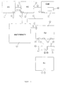
Figur 3- ein Blockschaltbild eines Sprachdatenmodems des erfindungsgemäßen Kommunikationssystems nach Figur 1;
Figur 4- ein Blockschaltbild einer Steuerungseinheit des erfindungsgemäßen Kommunikationssystems nach Figur 1; und
Figur 5- ein Blockschaltbild eines Benutzerendgeräts des erfindungsgemäßen Kommunikationssystems nach Figur 1;
Figur 6- ein Blockschaltbild einer RTC-Adapter-Schaltungsanordnung des erfindungsgemäßen Kommunikationssystems nach Figur 1;
Figur 7- ein Blockschaltbild einer elektronischen Türbedienungseinheit des erfindungsgemäßen Kommunikationssystems nach Figur 1; und
Figur 8- ein Blockschaltbild einer weiteren Ausführungsform des erfindungsgemäßen Kommunikationssystems.
- Figure 1
- a block diagram of the communication system according to the invention;
- Figure 2
- a block diagram of a communication center of the communication system according to the invention according to Figure 1;
- Figure 3
- a block diagram of a voice data modem of the communication system according to the invention according to Figure 1;
- Figure 4
- a block diagram of a control unit of the communication system according to the invention according to Figure 1; and
- Figure 5
- a block diagram of a user terminal of the communication system according to the invention according to Figure 1;
- Figure 6
- a block diagram of an RTC adapter circuit arrangement of the communication system of Figure 1;
- Figure 7
- a block diagram of an electronic door control unit of the communication system according to the invention according to Figure 1; and
- Figure 8
- a block diagram of another embodiment of the communication system according to the invention.
Wie aus Figur 1 ersichtlich weist das erfindungsgemäße Kommunikationssystem
eine Kommunikationszentrale 1, die die Funktion der zentralen Steuerung hat und
auch in Figur 2 dargestellt ist, eine Steuerungseinheit 2 (Figur 4) und mehrere
Benutzerendgeräte 3 (Figur 5) auf. Die Benutzerendgeräte 3 sind vorzugsweise
Fernsprechgeräte bzw. Einheiten, die ein Fernsprechendgerät 8 aufweisen. Ein
Benutzerendgerät bildet das zentrale Kommunikationsendgerät 51 (Figur 7). Die
genannten Systemkomponenten 1, 2, 3 und 51 sind über Verbindungselemente
(Stecker) 4 über Verbindungskabel 41 mit einem MATV/SMATV-Netz 5 verbunden.
In einer Ausführungsform der Erfindung besteht das MATV/SMATV-Netz aus
genau einem Antennenkabel 5, insbesondere aus einem Koaxialkabel, wie dies
auch in Figur 8 dargestellt ist. As can be seen from Figure 1, the communication system according to the invention
a
Das erfindungsgemäße System ist in der Weise ausgestaltet, dass es außer
Kommunikationsverbindungen zwischen dem zentralen Kommunikationsendgerät
51 einerseits und jeweils einem oder mehreren Benutzerendgeräten 3 (z.B. 301,
302, ... oder 30n; Figur 8) andererseits auch Kommunikationsverbindungen
zwischen zwei und mehr Benutzerendgeräten 3 (z.B. 301, 302, ... oder 30n; Figur
8) herstellt. So wird in dem Kommunikationssystem gemäß der Erfindung
beispielsweise eine Kommunikationsverbindung, insbesondere eine Fernsprechverbindung
zwischen dem Benutzerendgerät 301 und dem Benutzerendgerät 302
hergestellt. Das erfindungsgemäße Kommunikationssystem bietet damit auch die
Funktionen einer Fernmelde- bzw. Fernsprechnebenstellenanlage.The system according to the invention is designed in such a way that it is
Communication connections between the
Ebenso steuert das System Kommunikationsverbindungen, an denen eine andere
Systemeinheit (z.B. Alarmsensoren, Datenspeicher 58, etc.) und ein Benutzerendgerät
3 beteiligt ist.The system also controls communication connections on which another
System unit (e.g. alarm sensors,
Im Rahmen der hergestellten Kommunikationsverbindungen werden analoge und/oder digitale Daten übertragen.Within the framework of the established communication connections, analog and / or transmit digital data.
Die Steuerungseinheit 2 ist auch mit der Kommunikationszentrale 1 und mit verschiedenen
Einheiten, zu denen die Kopfeinheit 6 des MATV/SMATV-Systems
gehört, über Kommunikationselemente 7 mittels eines Verbindungsbusses 71
verbunden. Das Benutzerendgerät 3 ist mit einem Fernsprechendgerät 8, mit
einem weiteren Kommunikationssystem, insbesondere mit einem Fernsprechvermittlungssystem,
über Verbindungselemente bzw. Anschlüsse 9 mittels Kabel
91 und an wenigstens ein Fernsehgerät 60 und/oder ein Radiogerät 61 mittels
Kabel 91 verbunden. Das erfindungsgemäße System kann mit einem weiteren
Kommunikationssystem auch über die Zentrale 1 oder die Steuerungseinheit 2
verbunden sein.The
Die Kopfeinheit 6 ist eine Signalbearbeitungseinheit, die Signale, die über die
mindestens eine Antenne empfangen werden, bearbeitet. The
Die Signalbearbeitungs- bzw. Kopfeinheit 6 ist im erfindungsgemäßen Kommunikationssystem
von Systemeinheiten (z.B. 1, 2, 3, 51, 58) und/oder von einem
weiteren Kommunikationssystem, insbesondere von einem Fernmeldenetz steuerbar.The signal processing or
Der Signalbearbeitungseinheit 6 ist ein Speicher 58 zugeordnet, der Dienstleistungsdaten
enthält, mit denen Dienstleistungen innerhalb oder außerhalb des
Kommunikationssystems insbesondere zeitversetzt (nicht in Realzeit) erbracht
werden. So lassen sich Dienste realisieren, die eine Systemeinheit (z.B. Benutzerendgerät,
Steuerungseinrichtung, Komponente der Signalbearbeitungseinheit)
anfordert. Hierzu gehört das Abspielen eines abgespeicherten Films, die
Aktivierung des Betriebs von vorprogrammierten Einrichtungen, die Visualisierung
von Bildern, die Abfrage von Datenbeständen, etc.A
Der Speicher 58 ist für Systemeinheiten und/oder für mindestens ein externes
Kommunikationssystem, insbesondere für ein Fest- oder Mobilfernmeldenetz,
zugänglich. Die Daten, die in dem Speicher 58 gespeichert sind, sind in
Systemeinheiten und/oder in mindestens ein externes Kommunikationssystem,
insbesondere in ein Fest- oder Mobilfernmeldenetz, übertragbar. Der Speicher 58
ist insbesondere eine Festplatte, eine CD-ROM oder eine Diskette.The
Insbesondere kann mehr als eine Systemeinheit gleichzeitig Zugang zu dem
Speicher 58 haben, um auf dieselben oder auf unterschiedliche Daten, die in dem
Speicher 58 abgespeichert sind, zuzugreifen und/oder um Daten einzuschreiben.In particular, more than one system unit can access the at the
Das erfindungsgemäße Kommunikationssystem kann weiterhin in der Weise
ausgestaltet sein, dass Informationen (Betriebsinformationen) zwischen der
Signalbearbeitungseinheit 6 und mindestens einem Benutzerendgerät 3 uni- oder
bidirektional übertragen werden. Diese Informationen bezeichnen Betriebszustände
der Signalbearbeitungseinheit 6 und/oder die Funktionsweise dieser
Einheit 6 . Dabei bildet das Benutzerendgerät 3 Signale, die auf Betriebszustände
und/oder die Funktionsweise der Einheit 6 einwirken. Diese Signalbearbeitungseinheit
ist eine an sich bekannte Kopfeinheit, die beispielsweise
Verstärker, Wandler, Prozessoren, Transmodulatoren, usw. aufweist. Beispielsweise
bildet die Kopf- bzw. Signalbearbeitungseinheit ein Parameterauswahlmenü
und überträgt dieses an ein Benutzerendgerät, das das Menü
anfordert, beispielsweise in der Absicht, die gerade aktivierten Parameter der
Kopfeinheit zu ändern. Beispielsweise wird von einem Benutzerendgerät und
mittels des Menüs die Information an die Kopfeinheit übertragen, dass die
Abstimmung eines bestimmten Kanals zu ändern ist. Andere Beispiele für die
Parameter sind Ausgangsspannung, Audio- und Videopegel und Änderung eines
Empfangskanals.The communication system according to the invention can continue in this way
be designed so that information (operational information) between the
Eine andere Betriebsinformation, die von einem Benutzerendgerät 3 übermittelt
wird, ist eine Softwaredatei, die einen modifizierten Betrieb der Kopfeinheit 6
definiert. Auf diese Weise kann eine Person, die das System zu verwalten hat, in
einfacher Weise den Betrieb der Kopfeinheit teilweise oder komplett steuern.
Beispielsweise können den Benutzerendgeräten 3 und der Einheit 51 Benutzerberechtigungen
zugeordnet werden; hierzu gehören neue Benutzerberechtigungen,
die Zuordnung von Diensten zu Benutzern, das Sperren von Diensten
wegen Nichtzahlung, System- und Diensteabschaltungen usw.Another operating information transmitted by a
Das Kommunikationssystem kann auch in der Weise ausgestaltet sein, dass
Informationen (Betriebsinformationen) zwischen der Signalbearbeitungseinheit 6
und mindestens einem anderen Kommunikationssystem uni- oder bidirektional
übertragen werden, wobei die Informationen Betriebszustände der Signalbearbeitungseinheit
6 und/oder die Funktionsweise dieser Einheit 6 bezeichnen.
Das andere Kommunikationssystem, insbesondere ein Fernsprechnetz, bildet
Signale, die auf Betriebszustände und/oder die Funktionsweise der Einheit 6
einwirken.The communication system can also be designed in such a way that
Information (operational information) between the
Figur 2 zeigt ein Blockschaltbild der Kommunikationszentrale 1. Wie aus der Figur
zu entnehmen ist, besteht die Kommunikationszentrale 1 aus einer Datensprachbasis
11, einem Datensprachmodem 12, einer Betriebssteuerungseinheit
13, aus einem Schnittstellenbus 485 14 und einem Schnittstellenbus RS232 15. Figure 2 shows a block diagram of the
Es weist weiterhin Verbindungselemente 4 für die Verbindung mit dem MATV/-SMATV-Netz
5, Verbindungselemente 7 zur Verbindung mit der Steuerungseinheit
2 und verschiedenen Einheiten in der Kopfeinheit 6 sowie Verbindungselemente
10 zur Verbindung von Einheiten, die Eingangsdaten verarbeiten und
Ausgangsdaten bilden, auf.It also has
Die Datensprachbasis 11 besteht aus einem Mikroprozessor, der beispielsweise
entsprechend dem DECT-Kommunikationsstandard arbeitet, und aus einem
Speicher, der die Betriebssoftware des Mikroprozessors speichert.The
Das Datensprachmodem 12, besteht - wie in Figur 3 dargestellt - aus einem Eingang/Ausgang/-Koppelelement
16, einem Eingangs-Bandpassfilter 17 und einem
Ausgangs-Bandpassfilter 18, welche die Eingangs-Ausgangsstufe der Anordnung
bilden. Die Eingangs- und Ausgangssignale werden mittels einer Umschaltungsanordnung
19 getrennt.As shown in FIG. 3, the
Zur Bearbeitung des Eingangssignals weist das Datensprachmodem 12 eine erste
Mischschaltung 20 auf, deren Funktion es ist, das Eingangssignal in eine
Zwischenfrequenz (110 MHz) umzusetzen, wobei das Ausgangssignal einer Stufe
der ersten Zwischenfrequenz zugeführt wird, welche aus einem Verstärker 21 und
einem SAW-Filter 22 besteht, wobei eine zweite Mischschaltung 23 das Signal in
eine zweite Zwischenfrequenz (9.996 MHz) wandelt. Danach wird das Signal in
eine zweite Stufe der Zwischenfrequenz eingegeben, welche aus zwei Bandpässen
24 und 25 und Verstärkern 26 und 27 besteht.The
Danach wird das Signal einem Quadratur-Demodulator 28 zugeführt, aus
welchem Signal-(GFSK Gaucian Frequency Shiftling Keying)-Daten extrahiert
werden, die dann der Datensprachbasis 11 zugeführt werden. Die Mischwandlersignale
werden durch lokale Oszillatoren 29 und 30 generiert, die von PLL-Schaltungen
32 und 31 gesteuert werden.The signal is then fed to a
Das Ausgangssignal wird aus den Daten generiert, die von der Datensprachbasis
11 stammen. Das Signal wird frequenzmoduliert und einem Ausgang-Mischer 33
zugeführt und danach in einem Ausgangsverstärker 34 verstärkt und über die
Umschaltanordnung 19 dem Ausgang zugeführt.The output signal is generated from the data from the
Die Betriebs-Steuerungseinheit 13 besteht aus einem Mikroprozessor und einer
Speichereinrichtung, die die Betriebssoftware des Mikroprozessors speichert. Der
Mikroprozessor verwaltet die Kommunikationsbusse RS 2332 und 485.The
Figur 4 zeigt das Blockschaltbild der Steuerungseinheit 2. Diese besteht aus
einem Telefonmodem 35 für den Eingang und Ausgang der Daten aus dem und in
das Fernsprechvermittlungsnetz, einem Schnittstellenbus 485 14 und einem
Schnittstellenbus RS 232 15, über die die Anbindung an die Komponenten der
den Kopfeinheit 6 bzw. an unterschiedliche Datenverarbeitungseinrichtungen hergestellt
wird, sowie aus einem Steuerungsprozessor 36, der den gesamten
notwendigen Systemprozess durchführt. Außerdem weist die Steuerungseinrichtung
2 ein Untersystem 37 auf, das Bilder einfügt und das Bildschirmanzeigen
generiert, die über das MATV/SMATV-Netz 5 zu den Netzbenutzern übertragen
werden. Dieses Untersystem 37 besteht aus einem Sekundärprozesssor 38, der
die gesamte Konfiguration erstellt und den Betrieb des Untersystems steuert, dies
in Abhängigkeit von Befehlen des Steuerungsprozessors 36, von einer Speichereinrichtung
39, die Videobildschirmanzeigen speichert, und aus einer On Screen
Display-Schaltung (OSD) 40, die an ihrem Ausgang die Videobildschirmanzeigen
im Format RGB abgibt.Figure 4 shows the block diagram of the
Am Ausgang des Bildeinfügungssubsystems 37 ist in der Steuerungseinrichtung 2
ein RGB-PAL-Wandler 42 angeordnet, ein Modulator 43 und ein Up-Konverter 57,
der die Signale im RGB-Format, die von dem Subsystem 37 generiert worden
sind, in Signale im PAL-Standard-Format wandelt, und in einem Hochfrequenz
(RF)-Kanal angeordnet sind, für deren Verteilung über das MATV/SMATV-Netz.At the output of the
Ebenso verfügt die Steuerungseinheit 2 über Anschlüsse 4 zur Verbindung mit
dem MATV/SMATV-Netz 5, Anschlüsse 7 zur Verbindung mit dem Verbindungsbus
485 mit der Kopfeinheit 6 und der Kommunikationszentrale 1,
Anschlüsse 9 für den Zugang zum dem Fernsprechvermittlungsnetz und Anschlüsse
10 des Typs RS 232 für Datenverarbeitungseinrichtungen mit Datenein-
und -ausgängen.The
Figur 5 zeigt das Blockschaltbild des Benutzerendgeräts 3, das wie dargestellt ein
Datensprachmodem 12, ein Datensprachendgerät 44 und einen RTC-Adapter 45
aufweist. Es weist außerdem Anschlüsse 9 zum Anschluss an ein Fernsprechendgerät
8 und an das Fernsprechnetz auf sowie Anschlüsse 4 zum Anschluss an
an das MATV-SMATV-Netz 5.Figure 5 shows the block diagram of the
Das Datensprachendgerät 44 weist einen Mikroprozessor auf, dem Hardwarekomponenten hinzugefügt worden sind, die notwendig sind, um die Prozeduren im DECT-Standard durchzuführen.The data language terminal 44 has a microprocessor, the hardware components have been added that are necessary to complete the procedures in the DECT standard to perform.
Dieses Datensprachendgerät 44 verwaltet die Verbindungen zwischen dem Benutzerendgerät
3 und der Kommunikationszentrale 1 und führt die Steuerung des
RTC-Adapters 45 und des Datensprachmodems 12 durch, um die Funktionen
des Benutzerendgeräts 3 durchzuführen, wie beispielsweise (Sprach-)-Verbindungen
zu halten, die elektronische Türsprechanlage zu bedienen, insbesondere
die Tür zu öffnen, Befehle, die über die Tastatur des Endgeräts 3 eingegeben
werden, der Kopfeinheit zuzuführen und die elektronische Türsprechanlage zu
konfigurieren.This data voice terminal 44 manages the connections between the
Die RTC-Adapterschaltung 45, die in Figur 6 dargestellt ist, weist eine Schaltung
DAA 46, eine Schaltung SLIC 47, einen DTMF-Detektor 48, zwei Relais 49 und
einen Oszillator 50 auf. Die Adapterschaltung 45 stellt über das Anschlusselement
9 eine Verbindung zwischen Fernsprechvermittlungsnetz und Datensprachendgerät
44 her.The
Das MATV/SMATV-Netz 5 ist mit diesem Endgerät 44 über das Datensprachmodem
12 verbunden. Die Aufgabe des Adapters 45 besteht darin, die
verschiedenen Verbindungen, die von einer herkömmlichen Telefonleitung oder
von einer internen Telefonleitung kommen, über das Datensprachmodem 12 über
das Koaxialkabel 41 (siehe Figur 1) zu führen. Er ist in der Weise ausgestaltet,
dass interne oder externe Verbindungen weiterzuschalten, beliebige Verbindungen
zu halten, DTMF-Töne einzufügen, um gewünschte Funktionen auszuwählen,
beispielsweise die Auswahl des Verbindungstyps (interne oder externe
Verbindung), Aktivierung eines Wartezustandes, Öffnen der Tür und Versenden
von Daten.The MATV /
Die Schaltung DAA 46 fügt die DTMF-Töne, die von dem Datensprachendgerät 44
kommen, in die herkömmliche Telefonleitung bzw. -verbindung ein, extrahiert
DTMF-Töne, die eine Bedienperson von ihrem Telefon über die Telefonleitung zu
dem Datensprachendgerät 44 übermittelt hat. Diese Vorrichtung führt auch die
Funktion aus, Verbindungen zu halten, da DAA 46 im Zustand "abgenommener
Telefonhörer" bleibt, wenn während einer hergestellten externen Verbindung eine
interne Verbindung avisiert wird, die hergestellt werden soll. Die Elemente bzw.
Anschlüsse, die diese Schaltung steuern, sind EN_HOOK, die die Funktion des
Zustandes "Telefonhörer abgenommen" realisiert, und DET_RING, die informiert,
dass Verbindungen aus dem Vermittlungsnetz anstehen.The
Der Adapter 45 weist auch eine Schaltung SLIC 47 auf, deren Funktion es ist,
eine Telefonleitung nachzubilden, an die das Telefon angeschlossen ist, wenn
eine interne Verbindung über das Koaxialkabel ansteht. Diese Anordnung
generiert das Signal RING, das erforderlich ist, damit das Telefon Klingeltöne
abgibt, sowie die Spannung der Leitung, die den Betrieb des Endgeräts
ermöglicht. Die wichtigsten Steuerleitungen, die die Schaltung SLIC steuern, sind
DET_HOOK, die für die Erfassung des Zustands "Telefonhörer abgenommen" des
Benutzerendgeräts benutzt wird, und EN_RING, die benutzt wird, um die Übertragung
eines Klingelsignals zu dem Benutzerendgerät zu ermöglichen.The
Eine weitere Schaltung, die in den Adapter 45 aufgenommen wird, ist ein DTMF-Detektor
48, der die Töne erfasst, die der Benutzer im Falle einer externen
Verbindung über das Fernsprechvermittlungsnetz einführt, oder die der Benutzer
im Falle einer internen Verbindung über die Schaltung SLIC 47 einführt. Die
erfasste Information wird in das Datensprachendgerät 44 eingegeben, um dort
analysiert zu werden, so dass dem Benutzer ermöglicht wird, seine Tastatur
seines Telefons 8 zu benutzen, um die Verbindungen herzustellen bzw. weiterzuschalten,
zu halten, in einen Wartezustand zu versetzen, die Tür der Wohnanlage
zu öffnen oder einen beliebigen Befehl an die Kopfeinheit 6 zu senden.Another circuit that is included in
Figur 7 zeigt eine andere Ausführungsform des Benutzerendgeräts 3. Diese
Ausführungsform stellt die elektronische Türbedienungsvorrichtung 51 dar. Diese
Vorrichtung 51 weist ein Datensprachmodem 12 auf, ein Datensprachterminal 44,
eine Tastatur 52 für die Eingabe von Daten, eine optische Anzeigeeinrichtung
LCD 53 zur Anzeige von Nachrichten, ein Lautsprecher 54, ein Mikrophon 55 und
eine Türöffnungseinrichtung 56.
Die elektronische Türbedienungsvorrichtung 51 verwaltet bzw. steuert Kommunikation
und sowie das Öffnen der Tür.FIG. 7 shows another embodiment of the
The electronic
Zusammenfassend ist hervorzuheben, dass das erfindungsgemäße System in der
Weise ausgestaltet ist, dass (Sprach- und/oder Daten-)Verbindungen beispielsweise
zwischen den Systemkomponenten 1, 2, 3, 6, 8, 9, 51, 60, 61, ... usw. in
bidirektionaler Form hergestellt werden, und dass der gesamte Betrieb der
Kommunikationsverbindungen mit allen Systemkomponenten ermöglicht wird.
Insbesondere ermöglicht das System, Benutzungsrechte zu verwalten.
Ebenso ermöglicht es den Anschluss beliebiger Endgeräte über das Benutzerendgerät
3.
Der Anschluss von Endgeräten an das Antennenkabel (insbesondere an das
Koaxialkabel) 5, kann über beliebige Kanäle (RF, Koaxialkabel, Kabel mit Leiterpaaren,
usw.) erfolgen, wobei die jeweiligen Schnittstellen vorgesehen werden.In summary, it should be emphasized that the system according to the invention is designed in such a way that (voice and / or data) connections, for example between
It also enables the connection of any end devices via the
Terminal devices can be connected to the antenna cable (in particular to the coaxial cable) 5 via any channels (RF, coaxial cable, cable with pairs of conductors, etc.), the respective interfaces being provided.
Schließlich verfügt das erfindungsgemäße System über die Möglichkeit der Verbindung mit öffentlichen Netzen, sowohl von Systemendgeräten als auch von Verwaltungsgeräten aus. Finally, the system according to the invention has the possibility of Connection to public networks, both from system terminals and from Management devices.
- 1, CC1, CC
- Zentral-Steuerungseinheit, KommunikationszentraleCentral control unit, communication center
- 2, EC2, EC
- Steuerungseinheitcontrol unit
- 3, 301, ..., 30n, TU3, 301, ..., 30n, TU
- Benutzerendgerätuser terminal
- 44
- Schnittstelleninterfaces
- 5, MATV/SMATV5, MATV / SMATV
- Antennenkabel, MATV/SMATV-NetzAntenna cable, MATV / SMATV network
- 6, CAB6, CAB
- Signalbearbeitungseinheit, KopfeinheitSignal processing unit, head unit
- 77
- Schnittstelleinterface
- 8, TT8, TT
- Fernsprechertelephone
- 99
- Verbindungselementconnecting element
- 1010
- Schnittstelle RS232RS232 interface
- 11, BD11, BD
- DatensprachbasisData base language
- 12, MD12, MD
- DatensprachmodemData Voice Modem
- 13, GDC13, GDC
- Steuerungseinheitcontrol unit
- 14, BUS 48514, BUS 485
- Schnittstellenbus 485Interface bus 485
- 15, BUS RS23215, BUS RS232
- Schnittstellenbus RS 232RS 232 interface bus
- 1616
- Eingangs-/Ausgangs-KoppelelementInput / output coupling element
- 1717
- EingangsbandpaßEingangsbandpaß
- 1818
- Ausgangsbandpaßoutput bandpass
- 19, CIR19, CIR
- Umschaltungsanordnungswitching arrangement
- 2020
- Erste MischerschaltungsanordnungFirst mixer circuit arrangement
- 2121
- Verstärkeramplifier
- 22, SAW22, SAW
- SAW-FilterSAW filter
- 2323
- Zweite MischerschaltungsanordnungSecond mixer circuit arrangement
- 2424
- Bandpaßbandpass
- 2525
- Bandpaßbandpass
- 2626
- Verstärkeramplifier
- 2727
- Verstärkeramplifier
- 28, DEM28, DEM
- Quadraturdemodulatorquadrature
- 2929
- Lokaler OszillatorLocal oscillator
- 3030
- Lokaler OszillatorLocal oscillator
- 3131
- PLL PLL
- 3232
- PLLPLL
- 3333
- Ausgangsmischeroutput mixer
- 3434
- Ausgangswiderstandoutput resistance
- 35, MT35, MT
- FernsprechmodemTelephone modem
- 3636
- Steuerungsprozessorcontrol processor
- 3737
- Subsystem zur Einfügung von BildernSubsystem for inserting images
- 38, PS38, PS
- Sekundärprozessorsecondary processor
- 39, MEM39, MEM
- Speicheranordnungmemory array
- 40, OSD40, OSD
- Schaltungsanordnung "On Screen Display"Circuit arrangement "on screen display"
- 4141
- Koaxialkabelcoaxial
- 42, RGB/PAL42, RGB / PAL
- RGB-PAL-KonverterRGB PAL converter
- 43, MOD43, MOD
- Modulatormodulator
- 44, TDV44, TDV
- DatensprachendgerätData voice terminal
- 45, RTC45, RTC
- RTC-AdapterRTC Adapter
- 46, DAA46, DAA
- DAA-SchaltungsanordnungDAA circuitry
- 47, SLIC47, SLIC
- SLIC-SchaltungsanordnungSLIC circuit arrangement
- 48, DTMF48, DTMF
- DTMF-DetektorDTMF detector
- 49, REL49, REL
- Relaisanordnungrelay arrangement
- 50, OSC50, OSC
- Oszillatoroscillator
- 5151
- Elektronische Hausrufeinheit, zentrales KommunikationsendgerätElectronic house call unit, central communication terminal
- 52, TEC52, TEC
- Tastaturkeyboard
- 5353
- LCDLCD
- 54, ALT54, OLD
- Lautsprecherspeaker
- 55, MIC55, MIC
- Mikrophonmicrophone
- 56, AP56, AP
- TüröffnungseinheitDoor opening assembly
- 57, UP-C57, UP-C
- Up-KonverterUp-Converter
- 5858
- Datenträger, CD-ROM, DisketteData medium, CD-ROM, floppy disk
- 6060
- FernseherTV
- 6161
- Radioradio
- 7171
- Verbindungsbusconnecting bus
- 9191
- Kabelelectric wire
Claims (10)
dadurch gekenneichnet,
dass das Kommunikationssystem in der Weise ausgestaltet ist, dass die Zentral-Steuerungseinheit (1) Kommunikationsverbindungen zwischen mindestens zwei Benutzerendgeräten (3) und/oder Kommunikationsverbindungen steuert, an denen mindestens ein Benutzerendgerät (3) und/oder mindestens eine weitere Systemeinheit (6, 51, 58) und/oder ein weiteres Kommunikationssystem beteiligt ist.Communication system with at least one radio and / or television antenna, with at least one antenna cable (5) to which radio and / or television devices (60, 61) can be connected, with a central control unit (1) with a central communication terminal (51), and with user terminals (3), the communication system being designed in such a way that communication connections are established between the central communication terminal (51) on the one hand and a user terminal (3) on the other hand,
characterized by
that the communication system is designed in such a way that the central control unit (1) controls communication connections between at least two user terminals (3) and / or communication connections on which at least one user terminal (3) and / or at least one further system unit (6, 51 , 58) and / or another communication system is involved.
Applications Claiming Priority (7)
| Application Number | Priority Date | Filing Date | Title |
|---|---|---|---|
| ES200002050 | 2000-08-04 | ||
| ES200002050A ES2177412B1 (en) | 2000-08-04 | 2000-08-04 | COMMUNICATION SYSTEM APPLICABLE TO SMATV NETWORKS. |
| ES200002047A ES2176096B1 (en) | 2000-08-04 | 2000-08-04 | SIGNAL RECEPTION AND TREATMENT SYSTEM. |
| ES200002047 | 2000-08-04 | ||
| ES200002048A ES2177410B1 (en) | 2000-08-04 | 2000-08-04 | COMMUNICATION SYSTEM APPLICABLE TO RADIO AND / OR TV RECEPTION SYSTEMS. |
| ES200002048 | 2000-08-04 | ||
| DE10121292A DE10121292A1 (en) | 2000-08-04 | 2001-05-02 | Communication system has central control unit controlling communications links between user terminals and/or between user terminals and other communication system units or further communication system |
Publications (3)
| Publication Number | Publication Date |
|---|---|
| EP1182872A2 true EP1182872A2 (en) | 2002-02-27 |
| EP1182872A3 EP1182872A3 (en) | 2003-04-02 |
| EP1182872B1 EP1182872B1 (en) | 2009-07-15 |
Family
ID=27437964
Family Applications (1)
| Application Number | Title | Priority Date | Filing Date |
|---|---|---|---|
| EP01118953A Expired - Lifetime EP1182872B1 (en) | 2000-08-04 | 2001-08-04 | Communication system |
Country Status (3)
| Country | Link |
|---|---|
| EP (1) | EP1182872B1 (en) |
| DE (2) | DE10121292A1 (en) |
| ES (2) | ES2176096B1 (en) |
Cited By (1)
| Publication number | Priority date | Publication date | Assignee | Title |
|---|---|---|---|---|
| EP2367321A1 (en) | 2010-03-05 | 2011-09-21 | Televés, S.A. | Communications system |
Families Citing this family (2)
| Publication number | Priority date | Publication date | Assignee | Title |
|---|---|---|---|---|
| DE102005008125A1 (en) * | 2005-02-21 | 2006-09-07 | FTA Communications Technologies S.à.r.l. | LNB receiver |
| CN207355679U (en) * | 2017-03-06 | 2018-05-15 | 龚小华 | A kind of marcel waver |
Citations (3)
| Publication number | Priority date | Publication date | Assignee | Title |
|---|---|---|---|---|
| DE2951544A1 (en) * | 1979-12-21 | 1981-07-23 | Hermann 8500 Nürnberg Leber | Integrated communications system for hotel - includes unit control panel in each room and central control console for building |
| DE19811826A1 (en) * | 1997-06-26 | 1999-02-04 | Samsung Electronics Co Ltd | Personal computer communication and internet service via set top box |
| US6038425A (en) * | 1998-08-03 | 2000-03-14 | Jeffrey; Ross A. | Audio/video signal redistribution system |
Family Cites Families (2)
| Publication number | Priority date | Publication date | Assignee | Title |
|---|---|---|---|---|
| JPH0697787B2 (en) * | 1978-06-30 | 1994-11-30 | テレ−ズ インコ−ポレ−テツド | Subscriber TV charge calculation method |
| WO2000030354A1 (en) * | 1998-11-13 | 2000-05-25 | Discovery Communications, Inc. | Digital broadcast program ordering |
-
2000
- 2000-08-04 ES ES200002047A patent/ES2176096B1/en not_active Expired - Fee Related
-
2001
- 2001-05-02 DE DE10121292A patent/DE10121292A1/en not_active Ceased
- 2001-08-04 EP EP01118953A patent/EP1182872B1/en not_active Expired - Lifetime
- 2001-08-04 DE DE50114986T patent/DE50114986D1/en not_active Expired - Lifetime
- 2001-08-04 ES ES01118953T patent/ES2332986T3/en not_active Expired - Lifetime
Patent Citations (3)
| Publication number | Priority date | Publication date | Assignee | Title |
|---|---|---|---|---|
| DE2951544A1 (en) * | 1979-12-21 | 1981-07-23 | Hermann 8500 Nürnberg Leber | Integrated communications system for hotel - includes unit control panel in each room and central control console for building |
| DE19811826A1 (en) * | 1997-06-26 | 1999-02-04 | Samsung Electronics Co Ltd | Personal computer communication and internet service via set top box |
| US6038425A (en) * | 1998-08-03 | 2000-03-14 | Jeffrey; Ross A. | Audio/video signal redistribution system |
Cited By (1)
| Publication number | Priority date | Publication date | Assignee | Title |
|---|---|---|---|---|
| EP2367321A1 (en) | 2010-03-05 | 2011-09-21 | Televés, S.A. | Communications system |
Also Published As
| Publication number | Publication date |
|---|---|
| ES2332986T3 (en) | 2010-02-16 |
| DE50114986D1 (en) | 2009-08-27 |
| DE10121292A1 (en) | 2002-11-07 |
| EP1182872B1 (en) | 2009-07-15 |
| ES2176096B1 (en) | 2004-01-16 |
| ES2176096A1 (en) | 2002-11-16 |
| EP1182872A3 (en) | 2003-04-02 |
Similar Documents
| Publication | Publication Date | Title |
|---|---|---|
| DE69916623T2 (en) | AUDIO / VIDEO RE-DISTRIBUTION SYSTEM | |
| DE69721051T2 (en) | OFFICE BROADBAND COMMUNICATION SYSTEM USING TWISTED TWO-WIRE TELEPHONE LINES | |
| DE60022392T2 (en) | PROCESS AND DEVICE FOR PROVIDING LANGUAGE / UNITED NACHM SERVICES (EMS) WITH CABLE TELEVISION DEVICES | |
| DE60311139T2 (en) | ADDRESSABLE TELEPHONE SOCKET AND DATA NETWORK WITH SUCH TELEPHONE SOCKETS | |
| DE10393249T5 (en) | Community network system with broadband integrated service | |
| DE19741241A1 (en) | Video telephone device, method and system for audio and video conference calls and telephony | |
| DE19802226A1 (en) | Multimedia input / control device and method for multimedia communication | |
| DE102006058540A1 (en) | Multi handset cordless telephone with integrated video capabilities for baby monitoring, has door bell module comprising page button to transmit radio frequency message, that is coupled to wireless camera unit | |
| DE69914607T2 (en) | METHOD AND DEVICE FOR DATA COMMUNICATION | |
| AT15530U1 (en) | MULTICANAL VIDEO INTERCOM SYSTEM WITH ACCESS TO ADVANCED DIGITAL SERVICES | |
| DE10333818A1 (en) | Method and device for implementing a personnel management protection system | |
| EP1182872B1 (en) | Communication system | |
| EP0208959A1 (en) | Communication system | |
| WO2003017576A2 (en) | Method and system for communicating in a wireless communications network | |
| DE10116860A1 (en) | Signal reception and processing system for television, radio and/or data signals has memory within signal processing device used for holding services data | |
| DE3215261C2 (en) | ||
| DE19744056A1 (en) | Video telephone device, method and system for wireline audio and video conferencing and telephone calls | |
| DE19751870A1 (en) | Device, method and system for wireless audio and video conferencing and telephony | |
| DE10116384A1 (en) | Communication system esp. community antenna installation, uses user terminal to form signals for controlling operational state and mode of operation of signal processing unit | |
| DE10116549A1 (en) | Telephone system has controller that allows use for radio and video as well as other house based functions | |
| DE10116385A1 (en) | Communication system esp. community antenna TV systems for terrestrial or satellite transmitters, has central control unit designed to control communication links between at least two user terminals | |
| JPH10336614A (en) | Multiple dwelling house multimedia system | |
| DE19629773C1 (en) | Sound and video signal apparatus control system for various rooms of dwelling | |
| DE4221439A1 (en) | Hotel telephone system with message announcement facility - uses TV receiver at each telephone point for displaying message on screen | |
| DE19735384A1 (en) | Method, system and devices for radio connection of several end devices via a base station to an interface of a telephone or data network |
Legal Events
| Date | Code | Title | Description |
|---|---|---|---|
| PUAI | Public reference made under article 153(3) epc to a published international application that has entered the european phase |
Free format text: ORIGINAL CODE: 0009012 |
|
| AK | Designated contracting states |
Kind code of ref document: A2 Designated state(s): AT BE CH CY DE DK ES FI FR GB GR IE IT LI LU MC NL PT SE TR |
|
| AX | Request for extension of the european patent |
Free format text: AL;LT;LV;MK;RO;SI |
|
| RIN1 | Information on inventor provided before grant (corrected) |
Inventor name: FERNANDEZ CARNERO, JOSE LUIS, C/O TELEVES, S.A. Inventor name: BARREIRO TABOADA, CARLOS, C/O TELEVES, S.A. Inventor name: DE UNA PINERO, RAFAEL, C/O TELEVES, S.A. |
|
| PUAL | Search report despatched |
Free format text: ORIGINAL CODE: 0009013 |
|
| AK | Designated contracting states |
Kind code of ref document: A3 Designated state(s): AT BE CH CY DE DK ES FI FR GB GR IE IT LI LU MC NL PT SE TR |
|
| AX | Request for extension of the european patent |
Extension state: AL LT LV MK RO SI |
|
| 17P | Request for examination filed |
Effective date: 20031002 |
|
| AKX | Designation fees paid |
Designated state(s): DE ES FR GB IT PT |
|
| GRAP | Despatch of communication of intention to grant a patent |
Free format text: ORIGINAL CODE: EPIDOSNIGR1 |
|
| GRAS | Grant fee paid |
Free format text: ORIGINAL CODE: EPIDOSNIGR3 |
|
| GRAA | (expected) grant |
Free format text: ORIGINAL CODE: 0009210 |
|
| AK | Designated contracting states |
Kind code of ref document: B1 Designated state(s): DE ES FR GB IT PT |
|
| REG | Reference to a national code |
Ref country code: GB Ref legal event code: FG4D Free format text: NOT ENGLISH |
|
| REF | Corresponds to: |
Ref document number: 50114986 Country of ref document: DE Date of ref document: 20090827 Kind code of ref document: P |
|
| REG | Reference to a national code |
Ref country code: PT Ref legal event code: SC4A Free format text: AVAILABILITY OF NATIONAL TRANSLATION Effective date: 20091113 |
|
| REG | Reference to a national code |
Ref country code: ES Ref legal event code: FG2A Ref document number: 2332986 Country of ref document: ES Kind code of ref document: T3 |
|
| PLBE | No opposition filed within time limit |
Free format text: ORIGINAL CODE: 0009261 |
|
| STAA | Information on the status of an ep patent application or granted ep patent |
Free format text: STATUS: NO OPPOSITION FILED WITHIN TIME LIMIT |
|
| 26N | No opposition filed |
Effective date: 20100416 |
|
| PGFP | Annual fee paid to national office [announced via postgrant information from national office to epo] |
Ref country code: PT Payment date: 20130307 Year of fee payment: 13 |
|
| PGFP | Annual fee paid to national office [announced via postgrant information from national office to epo] |
Ref country code: DE Payment date: 20130831 Year of fee payment: 13 |
|
| PGFP | Annual fee paid to national office [announced via postgrant information from national office to epo] |
Ref country code: GB Payment date: 20130823 Year of fee payment: 13 Ref country code: FR Payment date: 20130820 Year of fee payment: 13 |
|
| PGFP | Annual fee paid to national office [announced via postgrant information from national office to epo] |
Ref country code: IT Payment date: 20130823 Year of fee payment: 13 |
|
| REG | Reference to a national code |
Ref country code: PT Ref legal event code: MM4A Free format text: LAPSE DUE TO NON-PAYMENT OF FEES Effective date: 20150204 |
|
| REG | Reference to a national code |
Ref country code: DE Ref legal event code: R119 Ref document number: 50114986 Country of ref document: DE |
|
| GBPC | Gb: european patent ceased through non-payment of renewal fee |
Effective date: 20140804 |
|
| PG25 | Lapsed in a contracting state [announced via postgrant information from national office to epo] |
Ref country code: PT Free format text: LAPSE BECAUSE OF NON-PAYMENT OF DUE FEES Effective date: 20150204 Ref country code: IT Free format text: LAPSE BECAUSE OF NON-PAYMENT OF DUE FEES Effective date: 20140804 |
|
| REG | Reference to a national code |
Ref country code: DE Ref legal event code: R119 Ref document number: 50114986 Country of ref document: DE Effective date: 20150303 |
|
| REG | Reference to a national code |
Ref country code: FR Ref legal event code: ST Effective date: 20150430 |
|
| PG25 | Lapsed in a contracting state [announced via postgrant information from national office to epo] |
Ref country code: DE Free format text: LAPSE BECAUSE OF NON-PAYMENT OF DUE FEES Effective date: 20150303 Ref country code: GB Free format text: LAPSE BECAUSE OF NON-PAYMENT OF DUE FEES Effective date: 20140804 |
|
| PG25 | Lapsed in a contracting state [announced via postgrant information from national office to epo] |
Ref country code: FR Free format text: LAPSE BECAUSE OF NON-PAYMENT OF DUE FEES Effective date: 20140901 |
|
| PGFP | Annual fee paid to national office [announced via postgrant information from national office to epo] |
Ref country code: ES Payment date: 20160727 Year of fee payment: 16 |
|
| REG | Reference to a national code |
Ref country code: ES Ref legal event code: FD2A Effective date: 20181029 |
|
| PG25 | Lapsed in a contracting state [announced via postgrant information from national office to epo] |
Ref country code: ES Free format text: LAPSE BECAUSE OF NON-PAYMENT OF DUE FEES Effective date: 20170805 |