EP1181702B1 - Bett-bediengerät für den pflegebereich - Google Patents
Bett-bediengerät für den pflegebereich Download PDFInfo
- Publication number
- EP1181702B1 EP1181702B1 EP00927216A EP00927216A EP1181702B1 EP 1181702 B1 EP1181702 B1 EP 1181702B1 EP 00927216 A EP00927216 A EP 00927216A EP 00927216 A EP00927216 A EP 00927216A EP 1181702 B1 EP1181702 B1 EP 1181702B1
- Authority
- EP
- European Patent Office
- Prior art keywords
- housing
- instrument according
- operating instrument
- bed operating
- wall
- Prior art date
- Legal status (The legal status is an assumption and is not a legal conclusion. Google has not performed a legal analysis and makes no representation as to the accuracy of the status listed.)
- Expired - Lifetime
Links
Images



Classifications
-
- A—HUMAN NECESSITIES
- A61—MEDICAL OR VETERINARY SCIENCE; HYGIENE
- A61G—TRANSPORT, PERSONAL CONVEYANCES, OR ACCOMMODATION SPECIALLY ADAPTED FOR PATIENTS OR DISABLED PERSONS; OPERATING TABLES OR CHAIRS; CHAIRS FOR DENTISTRY; FUNERAL DEVICES
- A61G7/00—Beds specially adapted for nursing; Devices for lifting patients or disabled persons
- A61G7/05—Parts, details or accessories of beds
-
- H—ELECTRICITY
- H01—ELECTRIC ELEMENTS
- H01H—ELECTRIC SWITCHES; RELAYS; SELECTORS; EMERGENCY PROTECTIVE DEVICES
- H01H9/00—Details of switching devices, not covered by groups H01H1/00 - H01H7/00
- H01H9/02—Bases, casings, or covers
- H01H9/0214—Hand-held casings
- H01H9/0228—Line cord switches
-
- A—HUMAN NECESSITIES
- A61—MEDICAL OR VETERINARY SCIENCE; HYGIENE
- A61G—TRANSPORT, PERSONAL CONVEYANCES, OR ACCOMMODATION SPECIALLY ADAPTED FOR PATIENTS OR DISABLED PERSONS; OPERATING TABLES OR CHAIRS; CHAIRS FOR DENTISTRY; FUNERAL DEVICES
- A61G2203/00—General characteristics of devices
- A61G2203/10—General characteristics of devices characterised by specific control means, e.g. for adjustment or steering
- A61G2203/12—Remote controls
-
- A—HUMAN NECESSITIES
- A61—MEDICAL OR VETERINARY SCIENCE; HYGIENE
- A61G—TRANSPORT, PERSONAL CONVEYANCES, OR ACCOMMODATION SPECIALLY ADAPTED FOR PATIENTS OR DISABLED PERSONS; OPERATING TABLES OR CHAIRS; CHAIRS FOR DENTISTRY; FUNERAL DEVICES
- A61G7/00—Beds specially adapted for nursing; Devices for lifting patients or disabled persons
- A61G7/002—Beds specially adapted for nursing; Devices for lifting patients or disabled persons having adjustable mattress frame
- A61G7/018—Control or drive mechanisms
-
- H—ELECTRICITY
- H01—ELECTRIC ELEMENTS
- H01H—ELECTRIC SWITCHES; RELAYS; SELECTORS; EMERGENCY PROTECTIVE DEVICES
- H01H9/00—Details of switching devices, not covered by groups H01H1/00 - H01H7/00
- H01H9/02—Bases, casings, or covers
- H01H9/04—Dustproof, splashproof, drip-proof, waterproof, or flameproof casings
Definitions
- the invention relates to a bed control device for the care sector with a housing and with controls suitable for the actuation of functional units is provided and at least are partially arranged on a wall of the housing.
- a bed control device is known a handheld device connected to a wall station via a cable having.
- the handset is used as a handset for one Telephone keyboard usual trained and points over it numerous buttons on the back with which various functions of numerous functional units triggered can be, so placing an emergency call, switching room lighting, selection of radio programs, switching on and off a television set and volume control.
- An electrical control unit with controls behind a continuous film on the wall of a waterproof housing is from DE 198 19 287 A1 known.
- the invention aims to provide a functionally reliable and easy to clean Bed control unit can be created for the care sector.
- a bed control device for the care sector with a housing and with controls suitable for the actuation of functional units is provided and at least are partially arranged on a wall of the housing, in which the wall of the housing on its outside at least sectionally has a continuous film that Housing is waterproof and the wall of the housing has at least one through opening, which with a sealed waterproof but water vapor permeable membrane is.
- the waterproof housing enables easy disinfection of the bed control unit by wiping with a damp cloth or even through Immerse as moisture penetrates the case is prevented. A leak test can be carried out during manufacture easily done by diving the device.
- the provision of a continuous film facilitates the waterproof Execution of the housing by adding additional seals can be saved, thereby increasing its functional reliability, especially when the device is used for a long time. at Using a transparent film, viewing windows for Warning lights or displays in a simple manner and without the use requiring additional seals to be manufactured.
- the bed control unit can be used as a wall station connected handheld device can be formed, the multiple buttons for Operation of various functional units, such as call systems, telecommunication devices, Radio and television sets.
- the wall of the housing at least one through opening has that with a water impermeable but water vapor permeable Membrane is closed, pressure equalization from the housing to the environment despite the watertight design of the housing possible. Water vapor can also escape from the housing, so that the housing can dry out. Sound transducers like microphones and sound generators like loudspeakers or earphones can be placed behind the membrane. On this way the case is fully waterproof Functionality of the sound converter and sound generator ensured.
- a membrane for example, a membrane made of a material on the market under the "Goretex" brand be used.
- a moisture sensor is in the housing is arranged. This makes permanent surveillance the moisture in the housing allows, which Functional reliability is further increased.
- the moisture sensor can be coupled to warning devices operating at a predetermined Moisture value, exceeding it to failure the electronics in the housing could give a warning signal. An expected malfunction can thus be displayed and the device can still be checked by service personnel before an actual malfunction has occurred. About that In addition, a leak test can be carried out at the end of the manufacturing process be monitored with the help of the humidity sensor. If the device is faulty, the moisture sensor will redeem Warning signal off.
- the film is towards the interior of the housing back at least partially provided with a plastic layer.
- This measure allows a mechanically stable execution of the housing, so that no leaks at mechanically high stressed areas of the housing are to be feared.
- window for displays or warning lights or recesses for sound transducers or sound generator and buttons can be done in a simple manner by leaving out the plastic layer during manufacture be provided.
- the Foil before applying the plastic layer on the inside printed so that decorations and symbols can be rubbed off and cleaned and disinfectant-proof.
- the housing can be manufactured by deep drawing the film and then back injection with plastic.
- the film advantageously has flexible sections, and the operating devices point through the flexible sections buttons formed on the film.
- the keys are therefore design-related waterproof since there are no openings or sealing gaps are present between the housing and the buttons.
- the production such buttons can be simply by omitting the back-injected Plastic layer done, with button symbols in front the back injection can be printed on the inside of the film can.
- the operating devices have a touch-sensitive keyboard.
- a touch sensitive keyboard has no moving parts and is therefore for the waterproof version of the bed control unit particularly suitable.
- Such a keyboard can behind a film window and in front of a display device can be arranged and for example part of an LCD display touch panel module his.
- the keyboard is behind one recessed portion of the wall of the housing arranged.
- a such arrangement of the keyboard increases the functional reliability of the Bed control unit by effectively protecting the keyboard from Bumps or unintentional actuation.
- the moisture sensor from two comb-like, interlocking and in short distance from each other arranged conductor tracks on a Printed circuit board is formed.
- Such training allows one simple execution of the moisture sensor without essential Additional costs, since the conductor tracks on one for accommodation of the electronic components of the operating devices existing circuit board can be provided anyway.
- Evaluation of the signal from the moisture sensor can be an analog input a microcontroller or a simple comparator circuit be used.
- a further increase in functional reliability can be arranged a circuit for monitoring the supply voltage and a temperature sensor can be achieved in the housing.
- a possible failure of the bed control unit can result Over or under voltage or due to overheating, for example due to excessive sun exposure, recognized early become.
- a receiving device for a transponder card is provided with the transmitting and / or receiving devices in Housing can be coupled.
- an identification card or payment card can be used on the handheld device without that tightness-impairing openings in the housing would have to be provided for such a card.
- the bed control device as a handheld device is formed and the housing is constructed from two half-shells is, a soft seal arranged between the half-shells is one over the outer wall of the housing has extending bead. Allow these measures an inexpensive and reliable construction of the housing, by, for example, a half shell all provided Has buttons and provided on their outer wall with a film is, whereas the other half shell is made of conventional Plastic injection molding exists.
- the rubber seal provided becomes a watertight Structure of the housing reached.
- a provided on the rubber seal The protruding bead protects the housing from bumps and can also be used for the passage of a Connection cable have an opening.
- the outer wall the housing has a continuous opening for the reception a bushing and the rubber seal open the opening has the portion surrounding the inside of the housing. Thereby can be a socket without additional separate seals attached to the housing and sealed.
- an emergency button on the housing is arranged and the rubber seal a flexible flat Has section that seen from the inside of the housing the emergency button is arranged.
- the movement of one on the case, usually placed in an easily accessible and clearly visible place, generally relatively large emergency button can do so over the flexible, flat section of the rubber seal into the Transfer the interior of the housing to the corresponding connection device become. This means that there is no complex sealing of the call button even required on the case as none from the inside of the case Continuous sealing gap between the emergency button and housing is present.
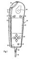
- the bed control device shown in FIG. 1 is a handheld device formed and has a housing 10 which consists of two half-shells 12 and 14 is constructed. This is via a connecting cable 16 Bed control unit connected to a wall station (not shown).
- the controls of the handheld device have a large emergency button 18, several small buttons 20 and a large area LCD touch panel module 22, which consists of a touch-sensitive Keyboard exists, which is deposited with an LCD display is.
- a circumferential rubber seal 24 is provided, the one beyond the outer wall of the housing 10 extending bead, which the housing 10 from shocks protects.
- a grommet 26 is in the rubber seal 24 Connection cable 16 introduced.
- the half-shell 12 shown in the figure 1 faces the viewer, points on its outside a continuous, transparent film that is deep-drawn and then back-injected with plastic for mechanical stabilization is.
- the LCD touch panel module 22 is behind one arranged transparent section of the film.
- the keys 20 are formed by flexible sections of the film, so that between the keys 20 and the half-shell 12 no sealing gap available where water or moisture can enter the handheld device could.
- the handheld device can also be used as a telephone handset, and so are in the continuous film on the outside of the half-shell 12 earpiece openings 28, behind which an earpiece is arranged and a very small microphone opening in diameter 30, behind which a microphone is provided.
- a Another opening 32 is used to arrange a jack socket.
- the earphone openings 28 will be described below and the microphone opening 30 through a membrane, the opening 32 whereas with a portion of the rubber seal 24 against sealed the ingress of water or moisture.
- the housing 10 of the handheld device is waterproof overall, so that Clean and disinfect damp wiping or even diving are harmless.
- FIG. 2 shows a partial sectional view of the bed control unit 1.
- the continuous film 34 is clearly visible in the area above the LCD touch panel module 22.
- the film 34 is transparent and forms a viewing window.
- There is a plastic layer above the transparent viewing window 36 can be seen with which the film 34 for mechanical Stabilization 36 is provided.
- the transparent film 34 is first with symbols for the Keys 20 and possibly a decor printed, then deep-drawn and finally injection molded with the plastic layer 36.
- the area of the keys 20 and the LCD touch panel module 22 is Cut out plastic layer 36.
- the earphone openings 28 have an earphone 38 in the housing 10 provided, which is arranged on a circuit board 40.
- the membrane 42 is a membrane made from a material known under the "Goretex" brand and prevents water from entering the housing 10 of the handheld device, but at the same time enables the passage of sound from the earphone 38 to the earphone openings 28. In addition can be compensated for by the membrane 42 from the inside of the Housing 10 to the environment.
- the circumferential seal 24, for example made of rubber has a flexible, flat in the area of the emergency button 18 Section 44 in which the emergency button 18 is performed and the seen from the inside of the housing 10, in front of the emergency button 18 is arranged.
- the transmission of the movement of the emergency button 18 on the components provided inside the housing 10, for example a simple switch is done by pushing it in the curvature of the as a soft (rubber) button with rigid Sealing frame trained emergency button.
- the emergency button 18 can not be sealed against the housing 10 because none from the inside of the housing 10 to the surroundings Sealing gap between emergency button 18 and housing 10 is present and the tightness of the housing 10 in the area of the emergency button 18 already guaranteed by section 44 of the rubber seal 24 is.
- FIG. 3 Another partial sectional view of the bed control unit of the figure 1 is shown in FIG. 3. Below the microphone opening 30 a microphone 46 can be seen.
- the microphone opening 30 has one very small diameter, so that only the smallest quantities anyway of water could enter them.
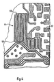
- Fig. 4 shows a section of a circuit board 52, which in the handheld device shown in FIG. 1 is arranged.
- This Printed circuit board 52 has a moisture sensor 54 which is made of there are two comb-like conductor tracks 56 and 58, which are in one another are arranged toothed.
- the conductor tracks 56 and 58 are small Spaced from each other and put in dry Condition is an isolated route. If water gets between the Conductor tracks 56 and 58, for example by condensation of in the moisture contained in the housing 10, the resistance changes between the conductor tracks 56 and 58, which makes even small Amounts of water are found within the housing 10 can.
- This change in resistance becomes an analog input microcontrollers arranged on the circuit board 52 (not shown) supplied, which is exceeded when a predefined Moisture value by a certain resistance value is defined between the conductor tracks 56 and 58, triggers a warning signal.
- the conductor tracks 56 and 58 are open for this executed, i.e. they are not isolating Layer, e.g. Solder mask, covered.
- A also serves for this purpose conventional temperature sensor provided on the circuit board 52 (not shown) with which an overshoot the maximum permissible operating temperature of the handheld device is detected can be. Even if the temperature is exceeded a warning signal is triggered so that the handheld device by the service personnel then be checked for functional reliability can.
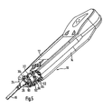
- FIG. 5 finally shows a further partial sectional view of the in the handheld device shown in FIG.
- the rubber seal 24 has an opening in the area of the introduction of the connecting cable 16 which is surrounded by a tubular extension 60 and into which the grommet 26 of the connecting cable 16 is inserted.
- the tubular Approach 60 seals the spout 26 and thus the insertion opening for the connecting cable 16 against the environment.
- a jack 62 is inserted, the its lower end is supported on the circuit board 52.
- the plastic layer 36 has a tubular Approach 64 on, in which the jack socket 62 is held.
- tubular section 66 of the rubber seal 24 is arranged, which is molded onto the circumferential rubber seal 24 and the sealing gap between the jack bushing 62 and the tubular one Approach 64 of the plastic layer.
- transponder card 71 On the outside of the lower half-shell 14, which in Fig. 6 for A viewer 70 is located a transponder card 71, which with transmitting and receiving devices can be coupled in the housing 10. In this way it is Use a card to identify a patient on the Handheld device possible without affecting the tightness of the housing Openings for the insertion of an identification card would have to be provided.
- the receiving device 70 consists of an insertion guide two edges 72 protruding on the outer edge as lateral Guide for the transponder card 71, the half in Fig. 6 is shown cut so that one under the transponder card 71 arrow 73 arranged in the guide area becomes visible, the as an elevation on the surface rising in the direction of the arrow of the corresponding area of the half-shell 14 can be that as a clamping point for the inserted transponder card 71 serves.
- a lower stop 74 and a bead 75 against slipping out complete the cradle 70th
Landscapes
- Health & Medical Sciences (AREA)
- Nursing (AREA)
- Life Sciences & Earth Sciences (AREA)
- Animal Behavior & Ethology (AREA)
- General Health & Medical Sciences (AREA)
- Public Health (AREA)
- Veterinary Medicine (AREA)
- Push-Button Switches (AREA)
- Casings For Electric Apparatus (AREA)
- Invalid Beds And Related Equipment (AREA)
Description
- Fig. 1
- eine perspektivische Ansicht der bevorzugten Ausführungsform des erfindungsgemäßen Bett-Bediengeräts;
- Fig. 2 und Fig. 3
- perspektivische Teilschnittansichten des in der Figur 1 gezeigten Bett-Bediengeräts;
- Fig. 4
- einen Ausschnitt aus einer Leiterplatte des in der Figur 1 gezeigten Bett-Bediengeräts mit einem Feuchtigkeitssensor;
- Fig. 5
- eine weitere perspektivische Teilschnittansicht des in der Figur 1 gezeigten Bett-Bediengeräts,
- Fig. 6
- eine perspektivische Ansicht der Rückseite des Bett-Bediengerätes der Fig. 1, und
- Fig. 7
- einen Teilschnitt durch das Bett-Bediengerät der Fig. 6 in vergrößerter Darstellung und längs der Linie VII-VII geschnitten.
Claims (13)
- Bett-Bediengerät für den Pflegebereich mit einem Gehäuse (10) und mit Bedienungseinrichtungen (18, 20, 22), die für die Betätigung von Funktionseinheiten vorgesehen und wenigstens teilweise an einer Wandung des Gehäuses (10) angeordnet sind, dadurch gekennzeichnet, daß die Wandung des Gehäuses (10) an ihrer Außenseite wenigstens abschnittsweise eine durchgehende Folie (34) aufweist, das Gehäuse (10) wasserdicht ausgeführt ist und die Wandung des Gehäuses (10) wenigstens eine durchgehende Öffnung (28, 30) aufweist, die mit einer wasserundurchlässigen aber wasserdampfdurchlässigen Membran (42, 48) verschlossen ist.
- Bett-Bediengerät nach Anspruch 1, dadurch gekennzeichnet, daß in dem Gehäuse (10) ein Feuchtigkeitssensor angeordnet ist.
- Bett-Bediengerät nach Anspruch 1 oder 2, dadurch gekennzeichnet, daß die Folie (34) zum Inneren des Gehäuses (10) hin wenigstens teilweise mit einer Kunststoffschicht (36) versehen ist.
- Bett-Bediengerät nach Anspruch 3, dadurch gekennzeichnet, daß die Folie (34) flexible Abschnitte aufweist und die Bedienungseinrichtungen durch die flexiblen Abschnitte der Folie (34) gebildete Tasten (20) aufweisen.
- Bett-Bediengerät nach einem der vorstehenden Ansprüche, dadurch gekennzeichnet, daß die Bedienungseinrichtungen eine berührungsempfindliche Tastatur (22) aufweisen.
- Bett-Bediengerät nach Anspruch 5, dadurch gekennzeichnet, daß die Tastatur (22) hinter einem vertieften Abschnitt der Wandung des Gehäuses (10) angeordnet ist.
- Bett-Bediengerät nach einem der Ansprüche 1 bis 6, dadurch gekennzeichnet, daß der Feuchtigkeitssensor (54) aus zwei kammartigen, ineinander verzahnten und in geringen Abstand voneinander angeordneten Leiterbahnen (56, 58) auf einer Leiterplatte (52) gebildet ist.
- Bett-Bediengerät nach einem der vorstehenden Ansprüche, dadurch gekennzeichnet, daß in dem Gehäuse (10) eine Schaltung zur Überwachung der Versorgungsspannung angeordnet ist.
- Bett-Bediengerät nach einem der vorstehenden Ansprüche, dadurch gekennzeichnet, daß in dem Gehäuse (10) ein Temperatursensor angeordnet ist.
- Bett-Bediengerät nach einem der vorstehenden Ansprüche, dadurch gekennzeichnet, daß an der Außenseite der Wandung des Gehäuses (10) eine Aufnahmevorrichtung für eine Transponderkarte vorgesehen ist, die mit Sende- und/oder Empfangsvorrichtungen im Gehäuse (10) koppelbar ist.
- Bett-Bediengerät nach einem der vorstehenden Ansprüche, dadurch gekennzeichnet, daß das Bett-Bediengerät als Handgerät ausgebildet ist und das Gehäuse (10) aus zwei Halbschalen (12, 14) aufgebaut ist, wobei zwischen den Halbschalen (12, 14) eine Dichtung (24) angeordnet ist, die einen sich über die Außenwandung des Gehäuses (10) hinaus erstreckenden Wulst (50) aufweist.
- Bett-Bediengerät nach Anspruch 11, dadurch gekennzeichnet, daß die Außenwandung des Gehäuses (10) eine durchgehende Öffnung (32) für die Aufnahme einer Buchse und die Dichtung (24) einen die Öffnung (32) auf der Innenseite des Gehäuses (10) umgebenden Abschnitt (66) aufweist.
- Bett-Bediengerät nach Anspruch 11 oder 12, dadurch gekennzeichnet, daß an dem Gehäuse (10) eine weiche Notruftaste (18) mit starrem Rahmen angeordnet ist und die Dichtung (24) einen flexiblen flächigen Abschnitt (44) aufweist, der vom Inneren des Gehäuses (10) aus gesehen vor der Notruftaste (18) angeordnet ist.
Applications Claiming Priority (5)
| Application Number | Priority Date | Filing Date | Title |
|---|---|---|---|
| DE19923395 | 1999-05-21 | ||
| DE19923395 | 1999-05-21 | ||
| DE19925051A DE19925051C2 (de) | 1999-05-21 | 1999-06-01 | Bett-Bediengerät für den Pflegebereich |
| DE19925051 | 1999-06-01 | ||
| PCT/EP2000/004508 WO2000072344A1 (de) | 1999-05-21 | 2000-05-18 | Bett-bediengerät für den pflegebereich |
Publications (2)
| Publication Number | Publication Date |
|---|---|
| EP1181702A1 EP1181702A1 (de) | 2002-02-27 |
| EP1181702B1 true EP1181702B1 (de) | 2003-07-16 |
Family
ID=26053463
Family Applications (1)
| Application Number | Title | Priority Date | Filing Date |
|---|---|---|---|
| EP00927216A Expired - Lifetime EP1181702B1 (de) | 1999-05-21 | 2000-05-18 | Bett-bediengerät für den pflegebereich |
Country Status (4)
| Country | Link |
|---|---|
| EP (1) | EP1181702B1 (de) |
| AT (1) | ATE245308T1 (de) |
| ES (1) | ES2202121T3 (de) |
| WO (1) | WO2000072344A1 (de) |
Families Citing this family (1)
| Publication number | Priority date | Publication date | Assignee | Title |
|---|---|---|---|---|
| US8350170B2 (en) | 2005-11-11 | 2013-01-08 | Linak A/S | Electric hand control, especially for electrically adjustable hospital and care beds |
Family Cites Families (12)
| Publication number | Priority date | Publication date | Assignee | Title |
|---|---|---|---|---|
| DE1905098U (de) * | 1964-04-09 | 1964-11-26 | Zettler Elektrotechn Alois | Fuer krankenbetten bestimmtes elektrisches signal- und schaltgeraet. |
| DE1690356B2 (de) * | 1967-05-31 | 1972-06-08 | Uninorm Etablissement, Vaduz | Handstueck mit schalt- und bedienungsgeraeten fuer elektrische krankenhauseinrichtungen und verfahren zu seiner herstellung |
| CH619563A5 (en) * | 1977-10-31 | 1980-09-30 | Bachmann Karl Ag | Electric contactor responding to humidity |
| DE3017874A1 (de) * | 1980-05-09 | 1981-11-12 | Siemens AG, 1000 Berlin und 8000 München | Gehaeuse fuer ein elektrisches bauelement |
| DE3122232A1 (de) * | 1981-06-04 | 1982-12-23 | Licentia Patent-Verwaltungs-Gmbh, 6000 Frankfurt | Sicherheitsvorrichtung fuer elektrisch betriebene geraete |
| US4598333A (en) * | 1985-09-12 | 1986-07-01 | Honeywell Inc. | Printed wiring board means with integral dew sensor |
| DE3826083A1 (de) * | 1988-07-30 | 1990-02-01 | Telefonbau & Normalzeit Gmbh | Bett-bediengeraet |
| WO1990006739A1 (de) * | 1988-12-16 | 1990-06-28 | Reimar Berger | Bediengerät |
| DE4108160C1 (de) * | 1991-03-14 | 1992-10-08 | Albert Ackermann Gmbh & Co Kg, 5270 Gummersbach, De | |
| DE29517561U1 (de) * | 1995-11-06 | 1995-12-21 | Handschuhfabrik Seiz GmbH & Co. KG, 72555 Metzingen | Mehrlagiges textiles Material |
| DE19708116C2 (de) * | 1997-02-28 | 1999-02-25 | Telefunken Microelectron | Anordnung zum Verschließen von Druckausgleichsöffnungen |
| DE19819287A1 (de) * | 1997-04-30 | 1998-11-05 | Leonische Drahtwerke Ag | Elektrisches Bauteil |
-
2000
- 2000-05-18 ES ES00927216T patent/ES2202121T3/es not_active Expired - Lifetime
- 2000-05-18 AT AT00927216T patent/ATE245308T1/de active
- 2000-05-18 EP EP00927216A patent/EP1181702B1/de not_active Expired - Lifetime
- 2000-05-18 WO PCT/EP2000/004508 patent/WO2000072344A1/de not_active Ceased
Also Published As
| Publication number | Publication date |
|---|---|
| EP1181702A1 (de) | 2002-02-27 |
| ES2202121T3 (es) | 2004-04-01 |
| WO2000072344A1 (de) | 2000-11-30 |
| ATE245308T1 (de) | 2003-08-15 |
Similar Documents
| Publication | Publication Date | Title |
|---|---|---|
| DE60210541T2 (de) | Benutzertauschbare Abdeckung für ein mobiles Telefon | |
| DE69734442T2 (de) | Funktelefon | |
| DE4498145C1 (de) | Flacheingabetastatur für Datenverarbeitungsgerät oder dergleichen sowie Verfahren zu ihrer Herstellung | |
| DE19853899C2 (de) | Vorrichtung zur elektrischen Verbindung eines Handys mit einer Tastatur | |
| DE4426812A1 (de) | Wasserdichtes Gehäuse mit Steckverbindung zum Schutz von Elektronikschaltkreisen | |
| DE102007047335A1 (de) | Hörgerät | |
| DE102007017773A1 (de) | Mobiles Kommunikationsgerät | |
| DE4447513C2 (de) | Wasserdichtes Gehäuse zum Schutz von Elektronikschaltkreisen | |
| DE202020000279U1 (de) | Schaltknopfeinrichtung umfassende Elektrogerätevorrichtung | |
| DE19925051C2 (de) | Bett-Bediengerät für den Pflegebereich | |
| DE29722222U1 (de) | Funkbetriebenes Kommunikationsendgerät mit Navigationstaste | |
| EP3245575A1 (de) | Folientastatur, hülle und mobiles endgerät mit einer solchen folientastatur sowie ladestation für ein mobiles endgerät | |
| EP3101918A2 (de) | Hörgerät | |
| DE69923343T2 (de) | Verfahren und vorrichtung zur kalibrierung einer widerstandsleiterschaltmatrix | |
| EP1181702A1 (de) | Bett-bediengerät für den pflegebereich | |
| DE202016107304U1 (de) | Wassergeschützter Handsender | |
| DE202009003843U1 (de) | Tastenanordnung mit einem elektronischen Bauelement sowie einer Drucktaste zum Betreiben des Bauelements | |
| DE3905130A1 (de) | Schalt- und/oder anzeigeeinheit fuer messgeraete, insbesondere waagen | |
| DE102007009816B4 (de) | Hör- /Sprechvorrichtung | |
| EP1836841B1 (de) | Bilderfassungseinrichtung | |
| EP1280390A2 (de) | Elektronischer Schlüssel für Fahrzeuge | |
| DE2523718C2 (de) | Anzeigefeld fuer die betriebsueberwachung nachrichtentechnischer geraete | |
| EP0846458A2 (de) | Fernbedienung für eine Massage- und/oder Sprudelvorrichtung | |
| DE102017104893B4 (de) | Optoelektronikmodul und Verfahren zur Herstellung eines Optoelektronikmoduls | |
| DE10022705C2 (de) | Mobiltelefon mit einem eingebauten Mikrofon, wobei der Schalleintritt durch Öffnungen im Gehäuse erfolgt |
Legal Events
| Date | Code | Title | Description |
|---|---|---|---|
| PUAI | Public reference made under article 153(3) epc to a published international application that has entered the european phase |
Free format text: ORIGINAL CODE: 0009012 |
|
| 17P | Request for examination filed |
Effective date: 20011002 |
|
| AK | Designated contracting states |
Kind code of ref document: A1 Designated state(s): AT BE CH CY DE DK ES FI FR GB GR IE IT LI LU MC NL PT SE |
|
| AX | Request for extension of the european patent |
Free format text: AL;LT;LV;MK;RO;SI |
|
| 17Q | First examination report despatched |
Effective date: 20020717 |
|
| GRAH | Despatch of communication of intention to grant a patent |
Free format text: ORIGINAL CODE: EPIDOS IGRA |
|
| GRAH | Despatch of communication of intention to grant a patent |
Free format text: ORIGINAL CODE: EPIDOS IGRA |
|
| GRAA | (expected) grant |
Free format text: ORIGINAL CODE: 0009210 |
|
| AK | Designated contracting states |
Designated state(s): AT BE CH CY DE DK ES FI FR GB GR IE IT LI LU MC NL PT SE |
|
| PG25 | Lapsed in a contracting state [announced via postgrant information from national office to epo] |
Ref country code: FI Free format text: LAPSE BECAUSE OF FAILURE TO SUBMIT A TRANSLATION OF THE DESCRIPTION OR TO PAY THE FEE WITHIN THE PRESCRIBED TIME-LIMIT Effective date: 20030716 Ref country code: CY Free format text: LAPSE BECAUSE OF FAILURE TO SUBMIT A TRANSLATION OF THE DESCRIPTION OR TO PAY THE FEE WITHIN THE PRESCRIBED TIME-LIMIT Effective date: 20030716 |
|
| REG | Reference to a national code |
Ref country code: GB Ref legal event code: FG4D Free format text: NOT ENGLISH |
|
| REG | Reference to a national code |
Ref country code: CH Ref legal event code: EP |
|
| REG | Reference to a national code |
Ref country code: CH Ref legal event code: NV Representative=s name: PATENTANWALTSBUERO PETSCHNER & PARTNER |
|
| REG | Reference to a national code |
Ref country code: IE Ref legal event code: FG4D Free format text: GERMAN |
|
| REF | Corresponds to: |
Ref document number: 50002918 Country of ref document: DE Date of ref document: 20030821 Kind code of ref document: P |
|
| PG25 | Lapsed in a contracting state [announced via postgrant information from national office to epo] |
Ref country code: GR Free format text: LAPSE BECAUSE OF FAILURE TO SUBMIT A TRANSLATION OF THE DESCRIPTION OR TO PAY THE FEE WITHIN THE PRESCRIBED TIME-LIMIT Effective date: 20031016 Ref country code: SE Free format text: LAPSE BECAUSE OF FAILURE TO SUBMIT A TRANSLATION OF THE DESCRIPTION OR TO PAY THE FEE WITHIN THE PRESCRIBED TIME-LIMIT Effective date: 20031016 Ref country code: DK Free format text: LAPSE BECAUSE OF FAILURE TO SUBMIT A TRANSLATION OF THE DESCRIPTION OR TO PAY THE FEE WITHIN THE PRESCRIBED TIME-LIMIT Effective date: 20031016 |
|
| GBT | Gb: translation of ep patent filed (gb section 77(6)(a)/1977) |
Effective date: 20031014 |
|
| PG25 | Lapsed in a contracting state [announced via postgrant information from national office to epo] |
Ref country code: PT Free format text: LAPSE BECAUSE OF FAILURE TO SUBMIT A TRANSLATION OF THE DESCRIPTION OR TO PAY THE FEE WITHIN THE PRESCRIBED TIME-LIMIT Effective date: 20031216 |
|
| LTIE | Lt: invalidation of european patent or patent extension |
Effective date: 20030716 |
|
| ET | Fr: translation filed | ||
| REG | Reference to a national code |
Ref country code: ES Ref legal event code: FG2A Ref document number: 2202121 Country of ref document: ES Kind code of ref document: T3 |
|
| PLBE | No opposition filed within time limit |
Free format text: ORIGINAL CODE: 0009261 |
|
| STAA | Information on the status of an ep patent application or granted ep patent |
Free format text: STATUS: NO OPPOSITION FILED WITHIN TIME LIMIT |
|
| PG25 | Lapsed in a contracting state [announced via postgrant information from national office to epo] |
Ref country code: BE Free format text: LAPSE BECAUSE OF NON-PAYMENT OF DUE FEES Effective date: 20040531 Ref country code: MC Free format text: LAPSE BECAUSE OF NON-PAYMENT OF DUE FEES Effective date: 20040531 |
|
| 26N | No opposition filed |
Effective date: 20040419 |
|
| BERE | Be: lapsed |
Owner name: ALBERT *ACKERMANN G.M.B.H. & CO. K.G. Effective date: 20040531 |
|
| PGFP | Annual fee paid to national office [announced via postgrant information from national office to epo] |
Ref country code: FR Payment date: 20060523 Year of fee payment: 7 Ref country code: NL Payment date: 20060523 Year of fee payment: 7 |
|
| PGFP | Annual fee paid to national office [announced via postgrant information from national office to epo] |
Ref country code: LU Payment date: 20060524 Year of fee payment: 7 Ref country code: IE Payment date: 20060524 Year of fee payment: 7 |
|
| PGFP | Annual fee paid to national office [announced via postgrant information from national office to epo] |
Ref country code: GB Payment date: 20060626 Year of fee payment: 7 |
|
| PGFP | Annual fee paid to national office [announced via postgrant information from national office to epo] |
Ref country code: CH Payment date: 20060627 Year of fee payment: 7 |
|
| PGFP | Annual fee paid to national office [announced via postgrant information from national office to epo] |
Ref country code: ES Payment date: 20060628 Year of fee payment: 7 |
|
| REG | Reference to a national code |
Ref country code: CH Ref legal event code: PL |
|
| GBPC | Gb: european patent ceased through non-payment of renewal fee |
Effective date: 20070518 |
|
| PG25 | Lapsed in a contracting state [announced via postgrant information from national office to epo] |
Ref country code: NL Free format text: LAPSE BECAUSE OF NON-PAYMENT OF DUE FEES Effective date: 20071201 |
|
| NLV4 | Nl: lapsed or anulled due to non-payment of the annual fee |
Effective date: 20071201 |
|
| REG | Reference to a national code |
Ref country code: IE Ref legal event code: MM4A |
|
| PG25 | Lapsed in a contracting state [announced via postgrant information from national office to epo] |
Ref country code: CH Free format text: LAPSE BECAUSE OF NON-PAYMENT OF DUE FEES Effective date: 20070531 Ref country code: LI Free format text: LAPSE BECAUSE OF NON-PAYMENT OF DUE FEES Effective date: 20070531 |
|
| REG | Reference to a national code |
Ref country code: FR Ref legal event code: ST Effective date: 20080131 |
|
| PG25 | Lapsed in a contracting state [announced via postgrant information from national office to epo] |
Ref country code: GB Free format text: LAPSE BECAUSE OF NON-PAYMENT OF DUE FEES Effective date: 20070518 Ref country code: IE Free format text: LAPSE BECAUSE OF NON-PAYMENT OF DUE FEES Effective date: 20070518 |
|
| PG25 | Lapsed in a contracting state [announced via postgrant information from national office to epo] |
Ref country code: FR Free format text: LAPSE BECAUSE OF NON-PAYMENT OF DUE FEES Effective date: 20070531 |
|
| REG | Reference to a national code |
Ref country code: ES Ref legal event code: FD2A Effective date: 20070519 |
|
| PG25 | Lapsed in a contracting state [announced via postgrant information from national office to epo] |
Ref country code: ES Free format text: LAPSE BECAUSE OF NON-PAYMENT OF DUE FEES Effective date: 20070519 |
|
| PG25 | Lapsed in a contracting state [announced via postgrant information from national office to epo] |
Ref country code: LU Free format text: LAPSE BECAUSE OF NON-PAYMENT OF DUE FEES Effective date: 20070518 |
|
| PGFP | Annual fee paid to national office [announced via postgrant information from national office to epo] |
Ref country code: IT Payment date: 20150519 Year of fee payment: 16 |
|
| PG25 | Lapsed in a contracting state [announced via postgrant information from national office to epo] |
Ref country code: IT Free format text: LAPSE BECAUSE OF NON-PAYMENT OF DUE FEES Effective date: 20160518 |
|
| PGFP | Annual fee paid to national office [announced via postgrant information from national office to epo] |
Ref country code: DE Payment date: 20170531 Year of fee payment: 18 |
|
| PGFP | Annual fee paid to national office [announced via postgrant information from national office to epo] |
Ref country code: AT Payment date: 20170426 Year of fee payment: 18 |
|
| REG | Reference to a national code |
Ref country code: DE Ref legal event code: R119 Ref document number: 50002918 Country of ref document: DE |
|
| REG | Reference to a national code |
Ref country code: AT Ref legal event code: MM01 Ref document number: 245308 Country of ref document: AT Kind code of ref document: T Effective date: 20180518 |
|
| PG25 | Lapsed in a contracting state [announced via postgrant information from national office to epo] |
Ref country code: AT Free format text: LAPSE BECAUSE OF NON-PAYMENT OF DUE FEES Effective date: 20180518 |
|
| PG25 | Lapsed in a contracting state [announced via postgrant information from national office to epo] |
Ref country code: DE Free format text: LAPSE BECAUSE OF NON-PAYMENT OF DUE FEES Effective date: 20181201 |