EP1181599B1 - Fiber optic light mixer - Google Patents
Fiber optic light mixer Download PDFInfo
- Publication number
- EP1181599B1 EP1181599B1 EP00966686A EP00966686A EP1181599B1 EP 1181599 B1 EP1181599 B1 EP 1181599B1 EP 00966686 A EP00966686 A EP 00966686A EP 00966686 A EP00966686 A EP 00966686A EP 1181599 B1 EP1181599 B1 EP 1181599B1
- Authority
- EP
- European Patent Office
- Prior art keywords
- mixer
- optical
- light
- send
- fibers
- Prior art date
- Legal status (The legal status is an assumption and is not a legal conclusion. Google has not performed a legal analysis and makes no representation as to the accuracy of the status listed.)
- Expired - Lifetime
Links
- 239000000835 fiber Substances 0.000 title claims abstract description 94
- 239000000523 sample Substances 0.000 claims abstract description 50
- 230000003287 optical effect Effects 0.000 claims abstract description 34
- 239000013307 optical fiber Substances 0.000 claims abstract description 15
- 230000001070 adhesive effect Effects 0.000 claims abstract description 13
- 239000000853 adhesive Substances 0.000 claims abstract description 12
- 230000005540 biological transmission Effects 0.000 claims abstract description 3
- 238000004891 communication Methods 0.000 claims description 4
- 230000013011 mating Effects 0.000 abstract description 6
- 238000013459 approach Methods 0.000 description 10
- 239000000463 material Substances 0.000 description 10
- 238000005259 measurement Methods 0.000 description 7
- 239000004820 Pressure-sensitive adhesive Substances 0.000 description 5
- 239000004033 plastic Substances 0.000 description 4
- 229920003023 plastic Polymers 0.000 description 4
- 239000004698 Polyethylene Substances 0.000 description 3
- 238000000034 method Methods 0.000 description 3
- -1 polyethylene Polymers 0.000 description 3
- 229920000573 polyethylene Polymers 0.000 description 3
- 239000004593 Epoxy Substances 0.000 description 2
- RRHGJUQNOFWUDK-UHFFFAOYSA-N Isoprene Chemical compound CC(=C)C=C RRHGJUQNOFWUDK-UHFFFAOYSA-N 0.000 description 2
- 230000002238 attenuated effect Effects 0.000 description 2
- 230000008901 benefit Effects 0.000 description 2
- 229920006332 epoxy adhesive Polymers 0.000 description 2
- 239000006260 foam Substances 0.000 description 2
- 239000011521 glass Substances 0.000 description 2
- 238000004519 manufacturing process Methods 0.000 description 2
- 238000012545 processing Methods 0.000 description 2
- 229920002943 EPDM rubber Polymers 0.000 description 1
- 229920000459 Nitrile rubber Polymers 0.000 description 1
- XTXRWKRVRITETP-UHFFFAOYSA-N Vinyl acetate Chemical compound CC(=O)OC=C XTXRWKRVRITETP-UHFFFAOYSA-N 0.000 description 1
- 239000000956 alloy Substances 0.000 description 1
- 229910045601 alloy Inorganic materials 0.000 description 1
- 210000003484 anatomy Anatomy 0.000 description 1
- 239000006117 anti-reflective coating Substances 0.000 description 1
- 230000003667 anti-reflective effect Effects 0.000 description 1
- 230000004888 barrier function Effects 0.000 description 1
- 238000005452 bending Methods 0.000 description 1
- 239000011248 coating agent Substances 0.000 description 1
- 238000000576 coating method Methods 0.000 description 1
- 230000000694 effects Effects 0.000 description 1
- 229920001971 elastomer Polymers 0.000 description 1
- 239000012530 fluid Substances 0.000 description 1
- 208000015181 infectious disease Diseases 0.000 description 1
- 230000007246 mechanism Effects 0.000 description 1
- 239000000203 mixture Substances 0.000 description 1
- 229920000515 polycarbonate Polymers 0.000 description 1
- 239000004417 polycarbonate Substances 0.000 description 1
- 229920000728 polyester Polymers 0.000 description 1
- 229920001296 polysiloxane Polymers 0.000 description 1
- 229920002635 polyurethane Polymers 0.000 description 1
- 239000004814 polyurethane Substances 0.000 description 1
- 229920000915 polyvinyl chloride Polymers 0.000 description 1
- 239000004800 polyvinyl chloride Substances 0.000 description 1
- 230000008569 process Effects 0.000 description 1
- 230000009467 reduction Effects 0.000 description 1
- 230000001105 regulatory effect Effects 0.000 description 1
- 230000002787 reinforcement Effects 0.000 description 1
- 239000005060 rubber Substances 0.000 description 1
- 239000004065 semiconductor Substances 0.000 description 1
- 229920002379 silicone rubber Polymers 0.000 description 1
- 239000004945 silicone rubber Substances 0.000 description 1
- 239000000758 substrate Substances 0.000 description 1
- 238000001356 surgical procedure Methods 0.000 description 1
- 238000012546 transfer Methods 0.000 description 1
- 230000032258 transport Effects 0.000 description 1
Images


Classifications
-
- G—PHYSICS
- G01—MEASURING; TESTING
- G01J—MEASUREMENT OF INTENSITY, VELOCITY, SPECTRAL CONTENT, POLARISATION, PHASE OR PULSE CHARACTERISTICS OF INFRARED, VISIBLE OR ULTRAVIOLET LIGHT; COLORIMETRY; RADIATION PYROMETRY
- G01J3/00—Spectrometry; Spectrophotometry; Monochromators; Measuring colours
- G01J3/02—Details
- G01J3/0205—Optical elements not provided otherwise, e.g. optical manifolds, diffusers, windows
- G01J3/0218—Optical elements not provided otherwise, e.g. optical manifolds, diffusers, windows using optical fibers
-
- G—PHYSICS
- G01—MEASURING; TESTING
- G01J—MEASUREMENT OF INTENSITY, VELOCITY, SPECTRAL CONTENT, POLARISATION, PHASE OR PULSE CHARACTERISTICS OF INFRARED, VISIBLE OR ULTRAVIOLET LIGHT; COLORIMETRY; RADIATION PYROMETRY
- G01J3/00—Spectrometry; Spectrophotometry; Monochromators; Measuring colours
- G01J3/02—Details
- G01J3/0205—Optical elements not provided otherwise, e.g. optical manifolds, diffusers, windows
- G01J3/0232—Optical elements not provided otherwise, e.g. optical manifolds, diffusers, windows using shutters
-
- G—PHYSICS
- G01—MEASURING; TESTING
- G01J—MEASUREMENT OF INTENSITY, VELOCITY, SPECTRAL CONTENT, POLARISATION, PHASE OR PULSE CHARACTERISTICS OF INFRARED, VISIBLE OR ULTRAVIOLET LIGHT; COLORIMETRY; RADIATION PYROMETRY
- G01J3/00—Spectrometry; Spectrophotometry; Monochromators; Measuring colours
- G01J3/02—Details
- G01J3/0291—Housings; Spectrometer accessories; Spatial arrangement of elements, e.g. folded path arrangements
-
- G—PHYSICS
- G01—MEASURING; TESTING
- G01N—INVESTIGATING OR ANALYSING MATERIALS BY DETERMINING THEIR CHEMICAL OR PHYSICAL PROPERTIES
- G01N21/00—Investigating or analysing materials by the use of optical means, i.e. using sub-millimetre waves, infrared, visible or ultraviolet light
- G01N21/17—Systems in which incident light is modified in accordance with the properties of the material investigated
- G01N21/25—Colour; Spectral properties, i.e. comparison of effect of material on the light at two or more different wavelengths or wavelength bands
- G01N21/27—Colour; Spectral properties, i.e. comparison of effect of material on the light at two or more different wavelengths or wavelength bands using photo-electric detection ; circuits for computing concentration
- G01N21/274—Calibration, base line adjustment, drift correction
-
- G—PHYSICS
- G01—MEASURING; TESTING
- G01N—INVESTIGATING OR ANALYSING MATERIALS BY DETERMINING THEIR CHEMICAL OR PHYSICAL PROPERTIES
- G01N21/00—Investigating or analysing materials by the use of optical means, i.e. using sub-millimetre waves, infrared, visible or ultraviolet light
- G01N21/17—Systems in which incident light is modified in accordance with the properties of the material investigated
- G01N21/25—Colour; Spectral properties, i.e. comparison of effect of material on the light at two or more different wavelengths or wavelength bands
- G01N21/31—Investigating relative effect of material at wavelengths characteristic of specific elements or molecules, e.g. atomic absorption spectrometry
- G01N21/314—Investigating relative effect of material at wavelengths characteristic of specific elements or molecules, e.g. atomic absorption spectrometry with comparison of measurements at specific and non-specific wavelengths
- G01N21/3151—Investigating relative effect of material at wavelengths characteristic of specific elements or molecules, e.g. atomic absorption spectrometry with comparison of measurements at specific and non-specific wavelengths using two sources of radiation of different wavelengths
-
- G—PHYSICS
- G02—OPTICS
- G02B—OPTICAL ELEMENTS, SYSTEMS OR APPARATUS
- G02B6/00—Light guides; Structural details of arrangements comprising light guides and other optical elements, e.g. couplings
- G02B6/24—Coupling light guides
- G02B6/26—Optical coupling means
- G02B6/28—Optical coupling means having data bus means, i.e. plural waveguides interconnected and providing an inherently bidirectional system by mixing and splitting signals
- G02B6/2804—Optical coupling means having data bus means, i.e. plural waveguides interconnected and providing an inherently bidirectional system by mixing and splitting signals forming multipart couplers without wavelength selective elements, e.g. "T" couplers, star couplers
- G02B6/2808—Optical coupling means having data bus means, i.e. plural waveguides interconnected and providing an inherently bidirectional system by mixing and splitting signals forming multipart couplers without wavelength selective elements, e.g. "T" couplers, star couplers using a mixing element which evenly distributes an input signal over a number of outputs
-
- G—PHYSICS
- G02—OPTICS
- G02B—OPTICAL ELEMENTS, SYSTEMS OR APPARATUS
- G02B6/00—Light guides; Structural details of arrangements comprising light guides and other optical elements, e.g. couplings
- G02B6/24—Coupling light guides
- G02B6/36—Mechanical coupling means
- G02B6/38—Mechanical coupling means having fibre to fibre mating means
- G02B6/3807—Dismountable connectors, i.e. comprising plugs
- G02B6/381—Dismountable connectors, i.e. comprising plugs of the ferrule type, e.g. fibre ends embedded in ferrules, connecting a pair of fibres
- G02B6/3825—Dismountable connectors, i.e. comprising plugs of the ferrule type, e.g. fibre ends embedded in ferrules, connecting a pair of fibres with an intermediate part, e.g. adapter, receptacle, linking two plugs
-
- G—PHYSICS
- G02—OPTICS
- G02B—OPTICAL ELEMENTS, SYSTEMS OR APPARATUS
- G02B6/00—Light guides; Structural details of arrangements comprising light guides and other optical elements, e.g. couplings
- G02B6/24—Coupling light guides
- G02B6/36—Mechanical coupling means
- G02B6/38—Mechanical coupling means having fibre to fibre mating means
- G02B6/3807—Dismountable connectors, i.e. comprising plugs
- G02B6/3873—Connectors using guide surfaces for aligning ferrule ends, e.g. tubes, sleeves, V-grooves, rods, pins, balls
- G02B6/3885—Multicore or multichannel optical connectors, i.e. one single ferrule containing more than one fibre, e.g. ribbon type
-
- G—PHYSICS
- G01—MEASURING; TESTING
- G01N—INVESTIGATING OR ANALYSING MATERIALS BY DETERMINING THEIR CHEMICAL OR PHYSICAL PROPERTIES
- G01N21/00—Investigating or analysing materials by the use of optical means, i.e. using sub-millimetre waves, infrared, visible or ultraviolet light
- G01N21/17—Systems in which incident light is modified in accordance with the properties of the material investigated
- G01N21/25—Colour; Spectral properties, i.e. comparison of effect of material on the light at two or more different wavelengths or wavelength bands
- G01N21/31—Investigating relative effect of material at wavelengths characteristic of specific elements or molecules, e.g. atomic absorption spectrometry
- G01N21/35—Investigating relative effect of material at wavelengths characteristic of specific elements or molecules, e.g. atomic absorption spectrometry using infrared light
- G01N21/3563—Investigating relative effect of material at wavelengths characteristic of specific elements or molecules, e.g. atomic absorption spectrometry using infrared light for analysing solids; Preparation of samples therefor
-
- G—PHYSICS
- G02—OPTICS
- G02B—OPTICAL ELEMENTS, SYSTEMS OR APPARATUS
- G02B6/00—Light guides; Structural details of arrangements comprising light guides and other optical elements, e.g. couplings
- G02B6/24—Coupling light guides
- G02B6/42—Coupling light guides with opto-electronic elements
- G02B6/4201—Packages, e.g. shape, construction, internal or external details
- G02B6/4249—Packages, e.g. shape, construction, internal or external details comprising arrays of active devices and fibres
-
- G—PHYSICS
- G02—OPTICS
- G02B—OPTICAL ELEMENTS, SYSTEMS OR APPARATUS
- G02B6/00—Light guides; Structural details of arrangements comprising light guides and other optical elements, e.g. couplings
- G02B6/24—Coupling light guides
- G02B6/42—Coupling light guides with opto-electronic elements
- G02B6/4298—Coupling light guides with opto-electronic elements coupling with non-coherent light sources and/or radiation detectors, e.g. lamps, incandescent bulbs, scintillation chambers
Definitions
- Spectrophotometric-type instruments are known and used in a variety of applications.
- An instrument of this type is, for example, disclosed in the Anderson et al. U.S. Patent 5,879,294. These instruments transmit light at a number of predetermined wavelengths through the tissue being measured, and then collect and process the light. Measurements of the tissue parameters of interest are generated as a function of the attenuation of the light at these wavelengths by the tissue.
- Several different approaches for obtaining the different wavelength light signals are used.
- One approach is to transmit through and collect from the tissue broad bandwidth light, and to separate the different wavelength signals from the collected light prior to processing.
- Another approach is to use light emitting diodes (LEDs) or other sources to generate narrow bandwidth light beams (i.e., signals at the wavelengths of interest).
- LEDs light emitting diodes
- send fibers These narrow bandwidth beams are then individually transmitted to the tissue being measured by separate individual optical fibers sometimes referred to as send fibers.
- a drawback of the use of individual send fibers is that light from one or more of these fibers may be attenuated differently than the light from other fibers due to inhomogeneities on the surface of the tissue where the light exits the send fibers and is transmitted into the tissue (i.e. the tissue target). This drawback is possible even though the ends of the send fibers are located adjacent to one another. For example, the end of one of the fibers could be over a mole or hair, while the others are not. Inaccurate measurements can result from these circumstances.
- a number of approaches for combining light from individual optical fibers are known.
- One approach is to fuse the individual fibers into a common fiber.
- Another approach is to fixture the LEDs onto an integrating sphere which mixes the light.
- An optical fiber at the exit port of the integrating sphere transports the light to the tissue target.
- Yet another method is to utilize the waveguide effect of semiconductor and other materials.
- the present invention is an optical tissue probe, according to claim 1. It includes a plurality of optical send fibers having input and output ends and an optical mixer having input and output ends. The output ends of the send fibers are in optical communication with the input end.
- the probe provides a high degree of light mixing yet is capable of being efficiently manufactured.
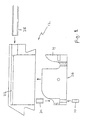
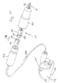
- Figures 1-6 illustrate an optical probe 12 which can be used in connection with the instrument shown in the Anderson et al. U.S. Patent 5,879,294 and which includes a light mixer 10 in accordance with a first embodiment of the present invention.
- the probe 12 includes an insert 14 for holding a number of optical fibers 16, 18 and 20, a housing 22 into which the insert is mounted and a disposable elastomeric tip 24 which is releasably mounted to the housing.
- the optical fibers 16, 18 and 20, which terminate at a tissue-facing surface 26 of the tip insert 14, are coupled between the housing 22 and instrument (not shown) within a cable housing 28.
- the illustrated embodiment of the probe 12 has 4 send fibers 16 through which light of different wavelengths from the instrument (provided by narrow bandwidth LEDs) is transmitted to the probe.
- the ends of the send fibers 16 are sealed in a ferrule 30.
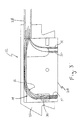
- the light mixer 10 is a section of optical fiber located between the fiber ferrule 30 and the tissue-facing surface 26 of the probe 12.
- the different wavelengths of light emitted from the ends of the send fibers 16 are mixed within the fiber of mixer 10 and thereby scattered throughout the surface area of the fiber at the tissue-facing surface 26. Each wavelength of light will thereby travel through a similar volume of tissue after being transmitted from the probe 12.
- a receive fiber 18 and a calibration recognition fiber 20 also have ends which terminate at the tissue-facing surface 26 of the probe 12.
- the receive fiber 18 collects light that has traveled through the tissue being analyzed and transmits the collected light to the instrument for processing. Light emitted from the calibration recognition fiber 20 is used by the instrument to control a calibration procedure.
- the light mixer 10 can be described with reference to Figures 1-8.
- the mixer 10 accepts, on its input side, light from the individual send fibers 16.
- the light mixer enhances the homogeneity of the light emitted on its output side and transmitted to the tissue The result is that variations (e.g., in intensity) in wavelength of light transmitted from the mixer 10 vs the position on the output end of the mixer are minimized. All wavelengths of the light entering the tissue will therefore be generally equally attenuated by the tissue, since a common entry point into the tissue will not bias any wavelength toward a longer or shorter path length than other wavelengths.
- This feature is illustrated diagrammatically in Figures 7 and 8 by the light ray reflections. Each wavelength of light is scattered over the whole cross-sectional area of the fiber of mixer 10, enabling each wavelength of light to travel through a similar volume of tissue.
- the output end of the mixer 10 is in direct contact with the tissue being measured through the probe window 32.
- a curved segment of optical fiber e.g. glass or plastic
- a numerical aperture (acceptance angle) greater than that of the send fibers 16 can be used for the mixer 10. Both ends of the mixer 10 can be polished clear.
- the output ends of the send fibers 16 can be in near direct contact (e.g., within about 0.025mm) with the input side of the mixer 10.
- the output end of the mixer 10 can be polished flat with the probe tip 12.
- the minimum diameter of the mixer 10 should be such that it is larger than the overall packed diameter of the input fibers 16. End faces of the mixer 10 fiber can also be coated with an anti-reflective material to increase throughput.
- One benefit of the larger diameter mixer 10 over that of a single fiber is a reduction in the power density present at the entrance point to the tissue, and therefore reduced regulatory issues (e.g. because there is less potential to locally heat or burn the tissue).
- the mixer 10 can be made from materials including glass and plastic fiber, and also have its faces angle polished.
- the mixing media need not necessarily be formed from fiber as it may take place in a free space area beyond where the fibers are recessed from the tissue-facing surface of the probe tip 12. Mixing can occur in a waveguide fashion prior to entering the tissue.
- the mixer 10 can also reside in an area other than the probe tip 12. For example, it can be located in the cable housing 28, closer to the instrument itself. However, the stiffness and bending radius of the cable assembly would then increase due to the presence of a larger diameter fiber.
- a plastic fiber can also be used, but if so it would be most advantageous in small lengths due to its attenuation properties at wavelengths typically used in spectrophotometric instruments.
- the mixer 10 it is not necessary that the mixer 10 be larger in diameter than the send fibers 16 or that it have a larger numerical aperture, but the intensity of light transmitted from the output of the mixer would be reduced under these circumstances. Similarly, an anti-reflective coating need not be present on the mixer 10, but throughput efficiency would likely be reduced without such a coating.
- the ends of the send fibers 16 can be secured in the combiner ferrule 30 with an optically-suitable epoxy and cured.
- the combiner ferrule 30 can then be cleaved and polished.
- the mixer 10 fiber can be cut to its desired approximate length and one end polished.
- the polished end can then be mounted to the polished end of the combiner ferrule 30 using epoxy adhesive.
- the output end of the mixer 10 fiber is mounted to the distal tip insert 14, for example with epoxy adhesive, and then cured.
- the distal end of the mixer 10 fiber on the tissue-engaging face 26 of the probe 12 can be cleaved and polished.
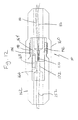
- a probe assembly 100 which includes a light mixer assembly 110 and probe tip 112 in accordance with a second embodiment of the present invention can be described with reference to Figures 9-12.
- the assembly 100 includes a cable housing 128 through which a plurality of send fibers 116 extend between the light mixer assembly 110 and light sources (not shown). In one embodiment the length of the send fibers 116 within the cable housing 128 is about 270 cm.
- a second cable housing 150 houses a mixer fiber 152 which extends between the assembly 110 and the tissue facing surface 126 of the probe insert 114. Mixer fiber 152 is about 30.5 cm long in one embodiment of the invention.
- the light mixer assembly 110 effectively splices the send fibers 116 to the mixer fiber 152 and includes a connector formed by outer shell 160, inner shell 162, send fiber ferrule 164, mixer fiber ferrule 166 and alignment pin 168.
- the send fibers 116 extend through the connector outer shell 160 and into send fiber ferrule 164.
- the ends of the send fibers 116 are secured (e.g., by an optical grade adhesive) in an aperture 170 in the send fiber ferrule 164, cleaved, and polished to provide an optical-quality mating surface.
- the end of the mixer fiber 152 extends through the connector inner shell 162 and into mixer fiber ferrule 166.
- the end of the mixer fiber 152 is located within an aperture 172 in the mixer fiber ferrule 166 and cleaved and polished to provide an optical-quality mating surface.
- Optical grade adhesive or other approaches can be used to secure the end of the mixer fiber 152 in the aperture 172 of the mixer fiber ferrule 166.
- Send fiber ferrule 164 includes a key alignment slot 180 which engages a key tab 184 within the inner shell 162 of the connector to align the ferrule and connector.
- the mixer fiber ferrule 166 includes a key alignment slot 182 which also engages key tab 184 within the inner shell 162 of the connector to align the ferrule and connector.
- the inner and outer connector shells 162 and 160 urge the faces of the ferrules 164 and 166 with the ends of the fibers 116 and 152, respectively, into optical engagement with one another. Forces to retain the faces of the ferrules 164 and 166 in engagement with one another can be provided by mating threads 190 and 192 on the outer and inner connector shells 160 and 162, respectively. Epoxy or other adhesive can also be used to secure the connector shells 160 and 162 together and thereby optically engage the send fibers 116 with the mixer fiber 152.
- a tensile reinforcement fiber (e.g., a length of braided polyethylene line, not shown) extending through the cable housings 128 and 150 and through the mixer assembly 110 can be wrapped and tied around the circumferential groove 194 to provide a strain relief on the fibers 116 and 152.
- the light mixer described herein has a greater efficiency (at least three to four times) than a 4:1 optical fiber combiner and waveguide material, and an approximately one-thousand times efficiency increase over integrating sphere approaches.
- the mixer is considerably less expensive to manufacture than known devices of the type described above.
- the device is no larger in size than a fiber combiner and waveguide, but is considerably smaller than an integrating sphere.
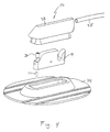
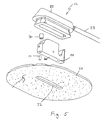
- the probe tip 24 is an elastomeric fixturing device which is used to reversibly attach the optical probe to a patient's tissue measurement site (e.g., the skin of a patient).
- the tip can be formed from a 1-piece elastomeric base member molded from flexible material such as silicone rubber (e.g., 50 shore A durometer from Applied Silicone) or polyethylene foam (e.g., Plastasote from Zotefoams Limited).
- suitable materials include isoprene/EPDM/nitrile rubbers, PVC, polyurethane, rubber alloys and vinyl acetate foams.
- An optically clear window (i.e., a window which transmits the light wavelengths of interest) separates the probe from the patient's skin, thereby functioning as a fluid/infection barrier.
- a pressure sensitive adhesive on the bottom or tissue-engaging surface of the base member holds the tip to the measurement site. Once removed from the patient's skin, the tip can be disposed.
- a probe-engaging recess in the base member is adapted to releasably secure the tip to the probe.
- the illustrated embodiment of the tip has a tapered cavity boot area which mates and fits snugly to the correspondingly tapered exterior surface of the tip housing. The described mating configuration enables the optical probe to be inserted into and removed from the tip without having to remove the tip from the patient.
- the material of the tip is optically opaque and has mating surfaces which overlap the reusable probe tip in a manner to trap ambient light.
- the tip preferably prevents or minimizes the amount of ambient light entering the tissue being measured near the measurement site. This property is accomplished by the extended tissue-engaging surface of the base member from the window.
- the fixture can be molded with a saddle or other shape which enables it to conform to the curvature of the leg, arm or other anatomy of the patient.
- a double-sided pressure sensitive adhesive can be bonded to the lower surface of the tip.
- the adhesive can be a transfer tape (unsupported pressure sensitive adhesive).
- a single coated tape pressure sensitive adhesive on the tissue-engaging side only
- the support carrier could also be used if the support carrier can be heat laminated or otherwise bonded to the elastomeric member.
- the adhesive and any associated support substrates should be optically clear if they are also functioning as the window.
- a separate section of optically clear material which does not have adhesive properties can be mounted to the tip to function as the window. Such a window component can be fixtured within the cavity of the tip.
- the window can be a thin (e.g., about 5 mil), thermoformed transparent (i.e., polyester, polyethylene or polycarbonate) plastic material molded to conform to the hole through the elastomeric tip member.
- the window can then be permanently mounted to the elastomeric base member by adhesive.
- a release liner can be used to protect the adhesive and window while the tip is being stored prior to use.
- the liner should be designed to be easily pulled off the tip to expose the pressure sensitive adhesive.
- the release liner can also be formed from optically clear materials, thereby allowing the tip to be used intermittently on a patient before the release liner is removed and the tip is fixedly mounted to the patient for continuous measurements.
- a non-transparent paper release liner can be used if the adhesive component is not designed to provide the window between the tip and probe.
- Structural approaches other than the elastomeric interference fit described above can be used to releasably secure the tip to the optical probe.
- snap-type or other buttons or latch mechanisms can be used for this purpose.
- the probe tip does not permanently fixture the optical components of the probe within a "patient sensor" Instead, the optical (and relatively expensive and functionally reusable) components can be removed from the patient without affecting the attachment of the tip to the patient.
- This reversibility of the probe connection to the patient allows the probe to be disconnected and reused on the same patient without having to issue a new disposable tip. In situations where a patient is temporarily removed from the instrument (e.g., for x-ray or surgery), the tip can remain attached to the patient and measurement later resumed.
- the present invention is a light mixer for use in connection with a spectrophotometric-type instrument having a plurality of optical send fibers for transmitting narrow bandwidth light of different wavelengths.
- the light mixer efficiently combines the light from the individual fibers into a generally homogeneous beam for transmission into the tissue being measured.
- the light mixer is located in the probe used to transmit the light into the tissue. In other embodiments the light mixer can be positioned at other locations between the probe and the LEDs or other sources of the narrow bandwidth light.
Landscapes
- Physics & Mathematics (AREA)
- Spectroscopy & Molecular Physics (AREA)
- General Physics & Mathematics (AREA)
- Health & Medical Sciences (AREA)
- Optics & Photonics (AREA)
- Immunology (AREA)
- Chemical & Material Sciences (AREA)
- Analytical Chemistry (AREA)
- Biochemistry (AREA)
- General Health & Medical Sciences (AREA)
- Life Sciences & Earth Sciences (AREA)
- Pathology (AREA)
- Toxicology (AREA)
- Engineering & Computer Science (AREA)
- Mathematical Physics (AREA)
- Theoretical Computer Science (AREA)
- Investigating Or Analysing Materials By Optical Means (AREA)
- Mechanical Coupling Of Light Guides (AREA)
- Measurement Of The Respiration, Hearing Ability, Form, And Blood Characteristics Of Living Organisms (AREA)
- Optical Couplings Of Light Guides (AREA)
Applications Claiming Priority (3)
| Application Number | Priority Date | Filing Date | Title |
|---|---|---|---|
| US13739099P | 1999-06-03 | 1999-06-03 | |
| US137390P | 1999-06-03 | ||
| PCT/US2000/015175 WO2000075701A2 (en) | 1999-06-03 | 2000-06-01 | Fiber optic light mixer |
Publications (2)
| Publication Number | Publication Date |
|---|---|
| EP1181599A2 EP1181599A2 (en) | 2002-02-27 |
| EP1181599B1 true EP1181599B1 (en) | 2003-03-05 |
Family
ID=22477211
Family Applications (1)
| Application Number | Title | Priority Date | Filing Date |
|---|---|---|---|
| EP00966686A Expired - Lifetime EP1181599B1 (en) | 1999-06-03 | 2000-06-01 | Fiber optic light mixer |
Country Status (6)
| Country | Link |
|---|---|
| US (1) | US6487343B1 (enExample) |
| EP (1) | EP1181599B1 (enExample) |
| JP (1) | JP2003501691A (enExample) |
| AU (1) | AU7699400A (enExample) |
| DE (1) | DE60001561T2 (enExample) |
| WO (1) | WO2000075701A2 (enExample) |
Families Citing this family (30)
| Publication number | Priority date | Publication date | Assignee | Title |
|---|---|---|---|---|
| US7676194B2 (en) * | 2003-08-22 | 2010-03-09 | Rappaport Theodore S | Broadband repeater with security for ultrawideband technologies |
| EP1746930A1 (en) * | 2004-05-18 | 2007-01-31 | Hutchinson Technology, Inc. | OPTIMIZED WAVELENGTH GAP FOR IMPROVED StO2 MEASUREMENT |
| US7239385B2 (en) * | 2004-11-30 | 2007-07-03 | Hutchinson Technology Incorporated | Method and apparatus for monitoring output signal instability in a light source |
| US7460897B1 (en) | 2005-05-16 | 2008-12-02 | Hutchinson Technology Incorporated | Patient interface for spectroscopy applications |
| US7596397B2 (en) * | 2005-05-16 | 2009-09-29 | Hutchinson Technology Incorporated | Patient interface for spectroscopy applications |
| US7355688B2 (en) * | 2005-09-08 | 2008-04-08 | Vioptix, Inc. | Optical probe for optical imaging system |
| US20080004513A1 (en) * | 2006-06-30 | 2008-01-03 | Walker Stephen D | VCSEL Tissue Spectrometer |
| US8742368B2 (en) | 2008-02-01 | 2014-06-03 | Cambridge Consultants Limited | Device and method for measuring scattering of radiation |
| US20090208173A1 (en) * | 2008-02-20 | 2009-08-20 | Schumann John L | Fiber cable terminator |
| US8938279B1 (en) | 2009-01-26 | 2015-01-20 | VioOptix, Inc. | Multidepth tissue oximeter |
| US8688186B1 (en) | 2009-02-04 | 2014-04-01 | Vioptix, Inc. | Retractor device with oximeter sensor and force sensor |
| US9486196B1 (en) | 2009-02-04 | 2016-11-08 | Vioptix, Inc. | Retractor systems with sensors |
| US9636096B1 (en) | 2009-02-04 | 2017-05-02 | Vioptix, Inc. | Retractor systems with closed loop control |
| WO2010098844A2 (en) | 2009-02-24 | 2010-09-02 | Adc Telecommunications, Inc. | Fiber optic cable pass-thru fitting |
| US9116310B2 (en) | 2009-03-06 | 2015-08-25 | Adc Telecommunications, Inc. | Fiber optic cable pass-thru fitting with a cable retention member for routing strength members |
| WO2010117656A2 (en) * | 2009-04-06 | 2010-10-14 | Adc Telecommunications, Inc. | Drop cable pass-thru fitting |
| US11179074B1 (en) * | 2009-05-08 | 2021-11-23 | Vioptix, Inc. | Probe for monitoring wet or moist environments |
| US8352008B2 (en) * | 2009-06-10 | 2013-01-08 | Medtronic, Inc. | Active noise cancellation in an optical sensor signal |
| US8571620B2 (en) | 2009-06-10 | 2013-10-29 | Medtronic, Inc. | Tissue oxygenation monitoring in heart failure |
| US8634890B2 (en) * | 2009-06-10 | 2014-01-21 | Medtronic, Inc. | Device and method for monitoring of absolute oxygen saturation and tissue hemoglobin concentration |
| US8391979B2 (en) * | 2009-06-10 | 2013-03-05 | Medtronic, Inc. | Shock reduction using absolute calibrated tissue oxygen saturation and total hemoglobin volume fraction |
| US8463346B2 (en) * | 2009-06-10 | 2013-06-11 | Medtronic, Inc. | Absolute calibrated tissue oxygen saturation and total hemoglobin volume fraction |
| US8521245B2 (en) * | 2009-09-11 | 2013-08-27 | Medtronic, Inc. | Method and apparatus for post-shock evaluation using tissue oxygenation measurements |
| US8290558B1 (en) | 2009-11-23 | 2012-10-16 | Vioptix, Inc. | Tissue oximeter intraoperative sensor |
| JP5710767B2 (ja) | 2010-09-28 | 2015-04-30 | マシモ コーポレイション | オキシメータを含む意識深度モニタ |
| US9775545B2 (en) | 2010-09-28 | 2017-10-03 | Masimo Corporation | Magnetic electrical connector for patient monitors |
| US8781547B2 (en) | 2011-10-28 | 2014-07-15 | Medtronic, Inc. | Method and apparatus for calibrating an absolute oxygen saturation sensor |
| US9907494B2 (en) | 2012-04-18 | 2018-03-06 | Hutchinson Technology Incorporated | NIRS device with optical wavelength and path length correction |
| US10154815B2 (en) | 2014-10-07 | 2018-12-18 | Masimo Corporation | Modular physiological sensors |
| JP6813953B2 (ja) * | 2016-02-29 | 2021-01-13 | シスメックス株式会社 | 血液凝固分析装置および血液凝固分析方法 |
Family Cites Families (14)
| Publication number | Priority date | Publication date | Assignee | Title |
|---|---|---|---|---|
| DE2205996B2 (de) | 1972-02-09 | 1975-05-15 | Rank Precision Industries Gmbh, 8500 Nuernberg | Faseroptische Lichtleiteranordnung, insbesondere Reflexionsschranke |
| US3874781A (en) | 1973-07-05 | 1975-04-01 | Corning Glass Works | Coupler for optical communication system |
| GB1558643A (en) | 1977-04-14 | 1980-01-09 | Standard Telephones Cables Ltd | Optical couplers |
| US4910539A (en) | 1988-12-27 | 1990-03-20 | General Dynamics Corporation, Electronics Division | RF frequency fiber optic power coupling device |
| US5224478A (en) | 1989-11-25 | 1993-07-06 | Colin Electronics Co., Ltd. | Reflecting-type oxymeter probe |
| US5212748A (en) | 1990-07-11 | 1993-05-18 | Curtiss Lawrence E | Fiber optic mixer and spectrometer |
| JPH04126125A (ja) * | 1990-09-18 | 1992-04-27 | Toshiba Corp | 内視鏡 |
| US5282466A (en) | 1991-10-03 | 1994-02-01 | Medtronic, Inc. | System for disabling oximeter in presence of ambient light |
| WO1994012096A1 (en) | 1992-12-01 | 1994-06-09 | Somanetics Corporation | Patient sensor for optical cerebral oximeters |
| JP2957055B2 (ja) * | 1992-12-08 | 1999-10-04 | 株式会社精工技研 | 光分岐結合器 |
| US5548672A (en) * | 1993-02-02 | 1996-08-20 | Sumitomo Electric Industries, Ltd. | Reinforced multicore optical fiber coupler |
| JPH09265019A (ja) * | 1996-03-27 | 1997-10-07 | Mitsubishi Gas Chem Co Inc | 光信号分配装置 |
| US5879294A (en) | 1996-06-28 | 1999-03-09 | Hutchinson Technology Inc. | Tissue chromophore measurement system |
| US5978534A (en) * | 1996-07-08 | 1999-11-02 | Equitech Int'l Corporation | Fiber optic raman probe and coupler assembly |
-
2000
- 2000-06-01 AU AU76994/00A patent/AU7699400A/en not_active Abandoned
- 2000-06-01 US US09/585,144 patent/US6487343B1/en not_active Expired - Fee Related
- 2000-06-01 WO PCT/US2000/015175 patent/WO2000075701A2/en not_active Ceased
- 2000-06-01 DE DE60001561T patent/DE60001561T2/de not_active Expired - Lifetime
- 2000-06-01 EP EP00966686A patent/EP1181599B1/en not_active Expired - Lifetime
- 2000-06-01 JP JP2001501920A patent/JP2003501691A/ja active Pending
Also Published As
| Publication number | Publication date |
|---|---|
| US6487343B1 (en) | 2002-11-26 |
| WO2000075701A3 (en) | 2001-08-23 |
| DE60001561D1 (de) | 2003-04-10 |
| WO2000075701A9 (en) | 2001-09-20 |
| JP2003501691A (ja) | 2003-01-14 |
| DE60001561T2 (de) | 2003-09-25 |
| WO2000075701A2 (en) | 2000-12-14 |
| AU7699400A (en) | 2000-12-28 |
| EP1181599A2 (en) | 2002-02-27 |
Similar Documents
| Publication | Publication Date | Title |
|---|---|---|
| EP1181599B1 (en) | Fiber optic light mixer | |
| US6892006B2 (en) | Fiber optic light mixer | |
| US6045502A (en) | Analyzing system with disposable calibration device | |
| US5754716A (en) | Optical mode mixer using fiber optic bundle | |
| US6839583B1 (en) | Disposable tissue probe tip | |
| EP0868881B1 (en) | Measuring condition setting fixture | |
| US6253097B1 (en) | Noninvasive medical monitoring instrument using surface emitting laser devices | |
| US6882873B2 (en) | Method and system for determining bilirubin concentration | |
| EP0501283B1 (en) | Optical organism measuring apparatus | |
| EP0234928A2 (en) | Optical fiber apparatus | |
| EP0702931A1 (en) | Noninvasive medical monitoring instrument | |
| US20130158413A1 (en) | Optical measurement of physiological blood parameters | |
| JPS59141932A (ja) | 代謝監視装置 | |
| JPH02206478A (ja) | 光診断装置 | |
| US7519407B2 (en) | Optical sensing catheter system | |
| JPH1068843A (ja) | 高反射減衰量型受光装置 | |
| WO2012158387A2 (en) | High-throughput alignment-insensitive optical connector for laser-based photoplethysmography | |
| US20210085160A1 (en) | Optical connection module for endoscope, endoscope, and endoscope system | |
| US8909313B2 (en) | Device for diagnosis and/or therapy of physiological characteristics of a selected portion of a body by optical reflectance or optical transmission | |
| JP2016202281A (ja) | 光プローブ | |
| WO1999005961A1 (en) | Analyzing system with disposable calibration device | |
| WO2000074562A1 (en) | Disposable tissue probe tip | |
| US20130253333A1 (en) | Tissue interface elements for application of optical signals into tissue of a patient | |
| JP3682809B2 (ja) | 生体計測装置 | |
| US5654539A (en) | Laser doppler optical sensor for use on a monitoring probe |
Legal Events
| Date | Code | Title | Description |
|---|---|---|---|
| PUAI | Public reference made under article 153(3) epc to a published international application that has entered the european phase |
Free format text: ORIGINAL CODE: 0009012 |
|
| 17P | Request for examination filed |
Effective date: 20011122 |
|
| AK | Designated contracting states |
Kind code of ref document: A2 Designated state(s): AT BE CH CY DE DK ES FI FR GB GR IE IT LI LU MC NL PT SE |
|
| AX | Request for extension of the european patent |
Free format text: AL;LT;LV;MK;RO;SI |
|
| RIN1 | Information on inventor provided before grant (corrected) |
Inventor name: SCHMIDT, MARK, A. Inventor name: QUAST, KENNETH, R. Inventor name: LEWANDOWSKI, MARK, S. Inventor name: MYERS, DEAN, E. |
|
| GRAG | Despatch of communication of intention to grant |
Free format text: ORIGINAL CODE: EPIDOS AGRA |
|
| 17Q | First examination report despatched |
Effective date: 20020627 |
|
| GRAG | Despatch of communication of intention to grant |
Free format text: ORIGINAL CODE: EPIDOS AGRA |
|
| GRAH | Despatch of communication of intention to grant a patent |
Free format text: ORIGINAL CODE: EPIDOS IGRA |
|
| GRAH | Despatch of communication of intention to grant a patent |
Free format text: ORIGINAL CODE: EPIDOS IGRA |
|
| GRAA | (expected) grant |
Free format text: ORIGINAL CODE: 0009210 |
|
| AK | Designated contracting states |
Designated state(s): DE FR GB IT |
|
| REG | Reference to a national code |
Ref country code: GB Ref legal event code: FG4D |
|
| REF | Corresponds to: |
Ref document number: 60001561 Country of ref document: DE Date of ref document: 20030410 Kind code of ref document: P |
|
| LTIE | Lt: invalidation of european patent or patent extension |
Effective date: 20030305 |
|
| ET | Fr: translation filed | ||
| PLBE | No opposition filed within time limit |
Free format text: ORIGINAL CODE: 0009261 |
|
| STAA | Information on the status of an ep patent application or granted ep patent |
Free format text: STATUS: NO OPPOSITION FILED WITHIN TIME LIMIT |
|
| 26N | No opposition filed |
Effective date: 20031208 |
|
| PGFP | Annual fee paid to national office [announced via postgrant information from national office to epo] |
Ref country code: IT Payment date: 20090625 Year of fee payment: 10 |
|
| PGFP | Annual fee paid to national office [announced via postgrant information from national office to epo] |
Ref country code: GB Payment date: 20090625 Year of fee payment: 10 |
|
| GBPC | Gb: european patent ceased through non-payment of renewal fee |
Effective date: 20100601 |
|
| PG25 | Lapsed in a contracting state [announced via postgrant information from national office to epo] |
Ref country code: IT Free format text: LAPSE BECAUSE OF NON-PAYMENT OF DUE FEES Effective date: 20100601 |
|
| PG25 | Lapsed in a contracting state [announced via postgrant information from national office to epo] |
Ref country code: GB Free format text: LAPSE BECAUSE OF NON-PAYMENT OF DUE FEES Effective date: 20100601 |
|
| PGFP | Annual fee paid to national office [announced via postgrant information from national office to epo] |
Ref country code: DE Payment date: 20110629 Year of fee payment: 12 |
|
| PGFP | Annual fee paid to national office [announced via postgrant information from national office to epo] |
Ref country code: FR Payment date: 20120705 Year of fee payment: 13 |
|
| REG | Reference to a national code |
Ref country code: DE Ref legal event code: R119 Ref document number: 60001561 Country of ref document: DE Effective date: 20130101 |
|
| PG25 | Lapsed in a contracting state [announced via postgrant information from national office to epo] |
Ref country code: DE Free format text: LAPSE BECAUSE OF NON-PAYMENT OF DUE FEES Effective date: 20130101 |
|
| REG | Reference to a national code |
Ref country code: FR Ref legal event code: ST Effective date: 20140228 |
|
| PG25 | Lapsed in a contracting state [announced via postgrant information from national office to epo] |
Ref country code: FR Free format text: LAPSE BECAUSE OF NON-PAYMENT OF DUE FEES Effective date: 20130701 |