EP1180582B1 - Vorrichtung zur relativen Drehwinkelverstellung einer Nockenwelle einer Brennkraftmaschine zu einem Antriebsrad - Google Patents
Vorrichtung zur relativen Drehwinkelverstellung einer Nockenwelle einer Brennkraftmaschine zu einem Antriebsrad Download PDFInfo
- Publication number
- EP1180582B1 EP1180582B1 EP01112996A EP01112996A EP1180582B1 EP 1180582 B1 EP1180582 B1 EP 1180582B1 EP 01112996 A EP01112996 A EP 01112996A EP 01112996 A EP01112996 A EP 01112996A EP 1180582 B1 EP1180582 B1 EP 1180582B1
- Authority
- EP
- European Patent Office
- Prior art keywords
- cellular wheel
- camshaft
- head part
- inner part
- webs
- Prior art date
- Legal status (The legal status is an assumption and is not a legal conclusion. Google has not performed a legal analysis and makes no representation as to the accuracy of the status listed.)
- Expired - Lifetime
Links
Images




Classifications
-
- F—MECHANICAL ENGINEERING; LIGHTING; HEATING; WEAPONS; BLASTING
- F01—MACHINES OR ENGINES IN GENERAL; ENGINE PLANTS IN GENERAL; STEAM ENGINES
- F01L—CYCLICALLY OPERATING VALVES FOR MACHINES OR ENGINES
- F01L1/00—Valve-gear or valve arrangements, e.g. lift-valve gear
- F01L1/34—Valve-gear or valve arrangements, e.g. lift-valve gear characterised by the provision of means for changing the timing of the valves without changing the duration of opening and without affecting the magnitude of the valve lift
- F01L1/344—Valve-gear or valve arrangements, e.g. lift-valve gear characterised by the provision of means for changing the timing of the valves without changing the duration of opening and without affecting the magnitude of the valve lift changing the angular relationship between crankshaft and camshaft, e.g. using helicoidal gear
- F01L1/3442—Valve-gear or valve arrangements, e.g. lift-valve gear characterised by the provision of means for changing the timing of the valves without changing the duration of opening and without affecting the magnitude of the valve lift changing the angular relationship between crankshaft and camshaft, e.g. using helicoidal gear using hydraulic chambers with variable volume to transmit the rotating force
-
- F—MECHANICAL ENGINEERING; LIGHTING; HEATING; WEAPONS; BLASTING
- F01—MACHINES OR ENGINES IN GENERAL; ENGINE PLANTS IN GENERAL; STEAM ENGINES
- F01L—CYCLICALLY OPERATING VALVES FOR MACHINES OR ENGINES
- F01L1/00—Valve-gear or valve arrangements, e.g. lift-valve gear
- F01L1/34—Valve-gear or valve arrangements, e.g. lift-valve gear characterised by the provision of means for changing the timing of the valves without changing the duration of opening and without affecting the magnitude of the valve lift
- F01L1/344—Valve-gear or valve arrangements, e.g. lift-valve gear characterised by the provision of means for changing the timing of the valves without changing the duration of opening and without affecting the magnitude of the valve lift changing the angular relationship between crankshaft and camshaft, e.g. using helicoidal gear
- F01L1/3442—Valve-gear or valve arrangements, e.g. lift-valve gear characterised by the provision of means for changing the timing of the valves without changing the duration of opening and without affecting the magnitude of the valve lift changing the angular relationship between crankshaft and camshaft, e.g. using helicoidal gear using hydraulic chambers with variable volume to transmit the rotating force
- F01L2001/3445—Details relating to the hydraulic means for changing the angular relationship
- F01L2001/34453—Locking means between driving and driven members
-
- F—MECHANICAL ENGINEERING; LIGHTING; HEATING; WEAPONS; BLASTING
- F01—MACHINES OR ENGINES IN GENERAL; ENGINE PLANTS IN GENERAL; STEAM ENGINES
- F01L—CYCLICALLY OPERATING VALVES FOR MACHINES OR ENGINES
- F01L1/00—Valve-gear or valve arrangements, e.g. lift-valve gear
- F01L1/34—Valve-gear or valve arrangements, e.g. lift-valve gear characterised by the provision of means for changing the timing of the valves without changing the duration of opening and without affecting the magnitude of the valve lift
- F01L1/344—Valve-gear or valve arrangements, e.g. lift-valve gear characterised by the provision of means for changing the timing of the valves without changing the duration of opening and without affecting the magnitude of the valve lift changing the angular relationship between crankshaft and camshaft, e.g. using helicoidal gear
- F01L1/3442—Valve-gear or valve arrangements, e.g. lift-valve gear characterised by the provision of means for changing the timing of the valves without changing the duration of opening and without affecting the magnitude of the valve lift changing the angular relationship between crankshaft and camshaft, e.g. using helicoidal gear using hydraulic chambers with variable volume to transmit the rotating force
- F01L2001/3445—Details relating to the hydraulic means for changing the angular relationship
- F01L2001/34453—Locking means between driving and driven members
- F01L2001/34456—Locking in only one position
-
- F—MECHANICAL ENGINEERING; LIGHTING; HEATING; WEAPONS; BLASTING
- F01—MACHINES OR ENGINES IN GENERAL; ENGINE PLANTS IN GENERAL; STEAM ENGINES
- F01L—CYCLICALLY OPERATING VALVES FOR MACHINES OR ENGINES
- F01L1/00—Valve-gear or valve arrangements, e.g. lift-valve gear
- F01L1/34—Valve-gear or valve arrangements, e.g. lift-valve gear characterised by the provision of means for changing the timing of the valves without changing the duration of opening and without affecting the magnitude of the valve lift
- F01L1/344—Valve-gear or valve arrangements, e.g. lift-valve gear characterised by the provision of means for changing the timing of the valves without changing the duration of opening and without affecting the magnitude of the valve lift changing the angular relationship between crankshaft and camshaft, e.g. using helicoidal gear
- F01L1/3442—Valve-gear or valve arrangements, e.g. lift-valve gear characterised by the provision of means for changing the timing of the valves without changing the duration of opening and without affecting the magnitude of the valve lift changing the angular relationship between crankshaft and camshaft, e.g. using helicoidal gear using hydraulic chambers with variable volume to transmit the rotating force
- F01L2001/3445—Details relating to the hydraulic means for changing the angular relationship
- F01L2001/34453—Locking means between driving and driven members
- F01L2001/34473—Lock movement perpendicular to camshaft axis
-
- Y—GENERAL TAGGING OF NEW TECHNOLOGICAL DEVELOPMENTS; GENERAL TAGGING OF CROSS-SECTIONAL TECHNOLOGIES SPANNING OVER SEVERAL SECTIONS OF THE IPC; TECHNICAL SUBJECTS COVERED BY FORMER USPC CROSS-REFERENCE ART COLLECTIONS [XRACs] AND DIGESTS
- Y10—TECHNICAL SUBJECTS COVERED BY FORMER USPC
- Y10T—TECHNICAL SUBJECTS COVERED BY FORMER US CLASSIFICATION
- Y10T74/00—Machine element or mechanism
- Y10T74/21—Elements
- Y10T74/2101—Cams
- Y10T74/2102—Adjustable
Definitions
- the invention relates to a device for the relative rotation angle adjustment Camshaft of an internal combustion engine to a drive wheel according to the genus of Main claim.
- the locking unit according to the invention is characterized by a simple structure from, in particular through a modification of the already existing components simple way a secure locking unit is created. At least one Part of the operating forces required for unlocking can be caused by the rotation of the Centrifugal force generated camshaft are applied.
- a supportive hydraulic Unlocking force is simple by a to the wing element of the Hydraulic line leading inside, realized by pressurizing it radially longitudinally displaceable head part of the wing against a spring force from a locked position can be transferred to an unlocked position.
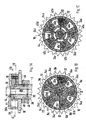
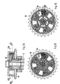
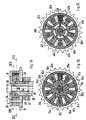
- FIG. 2 schematically shows the camshaft of an internal combustion engine indicated, at the free end of the rotor, hereinafter referred to as inner part 4, an adjusting unit 6 is arranged in a rotationally fixed manner.
- the inner part 4 is in this Embodiment with five radially arranged wings 8a to 8e provided by a hub 10 of the inner part 4 go out.
- the inner part 4 is in the area of its wings 8a to 8e by a cellular wheel 12, which has five inwardly projecting radial Webs 14a to 14e is provided. That representing the stator of the adjustment unit 6 Cell wheel 12 is on its end facing the camshaft 2 by a Sprocket 16 completed, the rotatable and sealing on the hub 10 of the Inner part 4 is guided.
- the sprocket 16 serves as a drive for the camshaft 2, the for example via a drive chain connected to the crankshaft.
- the opposite end of the cellular wheel 12 is from a disc 18th closed, the sprocket 16 and the disc 18 via fastening screws 20 are firmly connected to the cellular wheel 12.
- the in the webs 14a to 14e in Cell bores 12 provided through holes 22 are used for receiving or Guide these fastening screws 20.
- Through the webs 14a to 14e of the cellular wheel 12 are five limited by the chain wheel 16 and the disc 18 in the axial direction Cells formed by the wings 8a to 8e of the inner part 4 in two Pressure spaces 24a to 24e and 26a to 26e are divided.
- the inner part 4 and that on this rotatably guided cell wheel 12 are interconnected by a screw 28 connected.
- the hub 10 and the camshaft 2 have a central bore 30.
- the pressure spaces 24a to 24e are each radially in the hub 10 of the inner part 4th extending bores 32a to 32e connected to an annular space 34, which is between the fastening screw 28 for the adjusting unit 6 and the Wall sections of the central provided in the hub 10 and the camshaft 2 Bore 30 forms, the annular space 34 through the head 36 of the screw 28 is closed at the end.
- the annular space 34 is radial over several in the camshaft 2 introduced bores 38 with one arranged on the outer circumference of the camshaft 2 Ring groove 40 connected.
- the pressure spaces 26a to 26e are radially in the hub 10 of the Inner part 4 extending bores 42a to 42e with one on the outer circumference of the Camshaft 2 arranged annular groove 44 connected via five axially in the Camshaft 2 arranged bores 46a to 46e to another, also on Guide the outer circumference of the camshaft 2 formed annular groove 48.
- the two ring grooves 40, 48 are each via a acting as a rotary union Camshaft bearing 50 connected to a control line A and B.
- the two Control lines A and B are with a 4/2 proportional control valve, for example trained control valve 52 connected.
- This control valve 52 is also with a pressure medium pump 54 and an oil tank 56 connected.
- a check valve 58 is arranged in the pressure line P.
- the present exemplary embodiment is the adjusting unit 6 with its in FIG. 1 Locked end position shown for the adjustment of an exhaust camshaft provided, the cellular wheel 12 is driven clockwise while the Inner part 4 counterclockwise in the direction of "late" opening of the exhaust valves is adjustable.
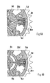
- the wing 8e of the inner part 4 is the wing 8e of the inner part 4 in Interacting with the web 14e of the cellular wheel 12 as one, closer below described locking unit formed.
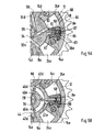
- the wing 8e has a head part 58, that by means of a groove-shaped recess 59 radially longitudinally displaceable on a Flat pin trained foot portion 60 of the wing 8e is mounted.
- the contour of the one Side surface of the head part 58 has two hook-shaped elements 61, which in the locked position of the camshaft adjuster in two according to the contour of the hook-shaped elements 61 engage adapted openings 62.
- the front of the Head part 58 has a rectangular recess 63 into which a plate element 64 intervenes.
- the plate element 64 is pressed against the inner wall by means of a compression spring 65 66 of the cellular wheel 12 pressed.
- To accommodate the compression spring 65 are on the front side of the head part 58 and in the plate element 64 bores 67 are provided.
- the Plate element 64 serves on the one hand as a seal between the two Pressure chambers 24e and 26e and on the other hand as a support or guide for a radial one Longitudinal displacement of the head part 58.
- a Supply channel 68 arranged with the via the annular groove 44 and the bore 46e Pressure oil is supplied.
- the internal combustion engine is out of operation, i.e. at standstill.
- the hook-shaped Elements 61 of the head part 58 engage in the openings 62.
- the control valve 52 remains de-energized, so that the Control line A is supplied to the pressure chambers 24a to 24e of oil. With that lies the inner part 4 with its wings 8a to 8e in its locked position on the webs 14a to 14e of the cellular wheel 12.
- the control valve 52 When the engine has reached a speed at which an adjustment of the camshaft 2 in Direction "late” is desired, the control valve 52 is energized. With that the Oil pressure supply via the control line B, the axial groove 48, the axial Bores 46a to 46e, the annular groove 44, the radial bores 42a to 42e and the Pressure chambers 26a to 26e supplied with oil. At the same time, the annular groove 44 and the Bore 46e of the supply channel 68 of oil arranged in the base part 60 of the wing 8e fed.
- the engine speed continues to increase, so that the oil pressure in the pressure chambers 26a to 26e increases, so that the inner part 4 or the rotor of the Camshaft adjuster is further adjusted counterclockwise.
- the engine speed has reached a value at which the engine speed proportionally increasing oil pressure in the pressure chambers 26a to 26e the wings 8a to 8e of the inner part 4 come to rest against the webs 14a to 14e of the cellular wheel 12 leaves.
- the maximum adjustment path of the camshaft adjuster is thus reached.
- the 4/2 proportional control valve 52 used provides an alternating control of the pressure spaces 24a to 24e or 26a to 26e possible, so that between the two Any intermediate positions can be approached and held.
- the hydraulic control of the camshaft adjuster can also be applied to others Way.
- two-point control is also possible, in which the camshaft adjuster only between its two end positions is adjustable.
- the vote to unlock the Wing 8e required operating forces designed in different ways his.
- the device is not based on the Hydraulic control described embodiment limited. It is also possible, instead of the one movable wing 8e, the other wings 8a to 8d in an analogous manner with a locking unit corresponding to the wing 8e and to equip the web 14e. Furthermore, it is also possible to open the wing 8e to provide its other side with locking elements, which then in corresponding Openings provided in the web 14d analogous to the web 14e when they are reached Intervene in end position.
Landscapes
- Engineering & Computer Science (AREA)
- Mechanical Engineering (AREA)
- General Engineering & Computer Science (AREA)
- Valve Device For Special Equipments (AREA)
Description
Claims (5)
- Vorrichtung zur relativen Drehwinkelverstellung einer Nockenwelle einer Brennkraftmaschine zu einem Antriebsrad, mit einem drehfest mit der Nockenwelle verbundenen Innenteil (4), das zumindest annähernd radial verlaufende Stege oder Flügel aufweist, und mit einem angetriebenen Zellenrad (12), das mehrere über den Umfang verteilte, durch Stege (14a bis 14e) begrenzte Zellen aufweist, die von den darin winkelbeweglich geführten Stegen oder Flügeln des Innenteils in zwei Druckräume unterteilbar sind, bei deren hydraulischer Druckbeaufschlagung bzw. Druckentlastung über Steuerleitungen die Nockenwelle über die Stege oder Flügel zwischen zwei Endstellungen relativ zum Zellenrad (12) verdrehbar ist, und mit mindestens einer zwischen Innenteil (4) und Zellenrad (12) wirksamen Verriegelungseinrichtung, mit der das Innenteil (4) gegenüber dem Zellenrad (12) in mindesten einer Endlage verriegelbar ist, wobei mindestens ein Flügel (8e) des Innenteils (4) ein Kopfteil (58) mit mindestens einem Verriegelungselement (61) aufweist, dadurch gekennzeichnet, dass dieses Verriegelungselement mit einer an mindestens einem Steg (14e) des Zellenrades (12) vorgesehenen Verriegelungsstruktur zusammenwirkt, wobei das Kopfteil (58) radial längsverschieblich ist und somit in Abhängigkeit von Betriebsparametern von einer verriegelten in eine entriegelte Position überführbar ist.
- Vorrichtung nach Anspruch 1, dadurch gekennzeichnet, dass das Kopfteil (58) auf einem Fußteil (60) des Flügels (8e) längsverschieblich gelagert ist.
- Vorrichtung nach Anspruch 1 oder 2, dadurch gekennzeichnet, dass das Kopfteil (58) aus einer verriegelten Position durch eine Öldruckbeaufschlagung und/oder durch Fliehkräfte in eine gegenüber dem Steg (14e) des Zellenrades 12 entriegelte Position überführbar ist.
- Vorrichtung nach einem der vorhergehenden Ansprüche, dadurch gekennzeichnet, dass das Kopfteil (58) hakenförmige Elemente (61) aufweist, die in der verriegelten Position in entsprechend der Kontur der hakenförmigen Elemente (61) angepasste Öffnungen (62) im Steg (14e) des Zellenrades (12) eingreifen.
- Vorrichtung nach einem der vorhergehenden Ansprüche, dadurch gekennzeichnet, dass die Stirnseite des Kopfteils (58) eine rechteckförmige Aussparung (63) aufweist, in die ein plattenförmiges Dicht- und Führungselement (64) eingreift, wobei das Dicht- und Führungselement (64) auf der Innenseite (66) des Zellenrades (12) abgestützt ist.
Applications Claiming Priority (2)
| Application Number | Priority Date | Filing Date | Title |
|---|---|---|---|
| DE10039913A DE10039913C1 (de) | 2000-08-16 | 2000-08-16 | Vorrichtung zur relativen Drehwinkelverstellung einer Nockenwelle einer Brennkraftmaschine zu einem Antriebsrad |
| DE10039913 | 2000-08-16 |
Publications (3)
| Publication Number | Publication Date |
|---|---|
| EP1180582A2 EP1180582A2 (de) | 2002-02-20 |
| EP1180582A3 EP1180582A3 (de) | 2002-11-06 |
| EP1180582B1 true EP1180582B1 (de) | 2004-01-28 |
Family
ID=7652543
Family Applications (1)
| Application Number | Title | Priority Date | Filing Date |
|---|---|---|---|
| EP01112996A Expired - Lifetime EP1180582B1 (de) | 2000-08-16 | 2001-06-11 | Vorrichtung zur relativen Drehwinkelverstellung einer Nockenwelle einer Brennkraftmaschine zu einem Antriebsrad |
Country Status (5)
| Country | Link |
|---|---|
| US (1) | US6584944B2 (de) |
| EP (1) | EP1180582B1 (de) |
| JP (1) | JP2002106310A (de) |
| DE (2) | DE10039913C1 (de) |
| ES (1) | ES2211695T3 (de) |
Families Citing this family (3)
| Publication number | Priority date | Publication date | Assignee | Title |
|---|---|---|---|---|
| JP4001070B2 (ja) * | 2003-07-22 | 2007-10-31 | アイシン精機株式会社 | 弁開閉時期制御装置 |
| DE10337587A1 (de) * | 2003-08-16 | 2005-03-10 | Ina Schaeffler Kg | Hydraulischer Nockenwellenversteller mit einem Freilauf |
| DE102006060676A1 (de) * | 2006-12-21 | 2008-06-26 | Schaeffler Kg | Steuerzeitenstellvorrichtung |
Family Cites Families (9)
| Publication number | Priority date | Publication date | Assignee | Title |
|---|---|---|---|---|
| US5823152A (en) * | 1995-06-14 | 1998-10-20 | Nippondenso Co., Ltd. | Control apparatus for varying a rotational or angular phase between two rotational shafts, preferably applicable to a valve timing control apparatus for an internal combustion engine |
| DE19808618A1 (de) * | 1998-02-28 | 1999-09-02 | Schaeffler Waelzlager Ohg | Verriegelungseinrichtung für eine Vorrichtung zum Verändern der Steuerzeiten von Gaswechselventilen einer Brennkraftmaschine, insbesondere für eine Flügelzellen-Verstelleinrichtung |
| JP3918971B2 (ja) * | 1998-04-27 | 2007-05-23 | アイシン精機株式会社 | 弁開閉時期制御装置 |
| JP3812137B2 (ja) * | 1998-04-28 | 2006-08-23 | アイシン精機株式会社 | 弁開閉時期制御装置 |
| JP3925672B2 (ja) * | 1998-05-28 | 2007-06-06 | アイシン精機株式会社 | 弁開閉時期制御装置 |
| DE19834843A1 (de) * | 1998-08-01 | 2000-02-03 | Porsche Ag | Einrichtung zur relativen Drehlagenänderung einer Welle zum Antriebsrad |
| JP3917772B2 (ja) * | 1999-02-04 | 2007-05-23 | 株式会社日立製作所 | 内燃機関の可変動弁装置 |
| JP2000337112A (ja) * | 1999-05-31 | 2000-12-05 | Unisia Jecs Corp | 内燃機関のバルブタイミング変更装置 |
| US6311655B1 (en) * | 2000-01-21 | 2001-11-06 | Borgwarner Inc. | Multi-position variable cam timing system having a vane-mounted locking-piston device |
-
2000
- 2000-08-16 DE DE10039913A patent/DE10039913C1/de not_active Expired - Fee Related
-
2001
- 2001-06-11 DE DE50101382T patent/DE50101382D1/de not_active Expired - Lifetime
- 2001-06-11 EP EP01112996A patent/EP1180582B1/de not_active Expired - Lifetime
- 2001-06-11 ES ES01112996T patent/ES2211695T3/es not_active Expired - Lifetime
- 2001-08-13 JP JP2001245210A patent/JP2002106310A/ja active Pending
- 2001-08-16 US US09/930,481 patent/US6584944B2/en not_active Expired - Fee Related
Also Published As
| Publication number | Publication date |
|---|---|
| JP2002106310A (ja) | 2002-04-10 |
| DE50101382D1 (de) | 2004-03-04 |
| EP1180582A3 (de) | 2002-11-06 |
| EP1180582A2 (de) | 2002-02-20 |
| DE10039913C1 (de) | 2001-10-18 |
| US6584944B2 (en) | 2003-07-01 |
| US20020026916A1 (en) | 2002-03-07 |
| ES2211695T3 (es) | 2004-07-16 |
Similar Documents
| Publication | Publication Date | Title |
|---|---|---|
| DE19914767C2 (de) | Ventilzeit-Steuerungseinrichtung | |
| EP1302630B1 (de) | Vorrichtung zum Verändern der Steuerzeiten von Gaswechselventilen einer Brennkraftmaschine, insbesondere Rotationskolben-Verstelleinrichtung zur Drehwinkelverstellung einer Nockenwelle gegenüber einer Kurbelwelle | |
| EP2470756B1 (de) | Steuerventil | |
| DE19623818A1 (de) | Steuervorrichtung zum Variieren einer Dreh- oder Winkelphase zwischen zwei drehenden Wellen, vorzugsweise anwendbar auf eine Ventilsteuerzeiten-Steuervorrichtung für einen Verbrennungsmotor | |
| EP1832723B1 (de) | Ventilsteuerung zur Einstellung des Hubes von Ventilen in einer Brennkraftmaschine | |
| WO2008135420A1 (de) | Nockenwellenversteller für eine brennkraftmaschine mit verbesserter ausführung der druckräume | |
| EP1896699A1 (de) | Steuerventil für eine vorrichtung zur variablen einstellung der steuerzeiten von gaswechselventilen einer brennkraftmaschine | |
| DE10055334C2 (de) | Vorrichtung zur relativen Drehwinkelverstellung einer Nockenwelle einer Brennkraftmaschine zu einem Antriebsrad | |
| DE19827930C2 (de) | Ventilsteuerungsvorrichtung | |
| DE102016225110B4 (de) | Ventilsteuerzeiteinstellvorrichtung für einen verbrennungsmotor | |
| EP1549828A1 (de) | Verriegelungseinrichtung für einen nockenwellenversteller | |
| DE102014214610B4 (de) | Nockenwellenverstellvorrichtung für eine Brennkraftmaschine | |
| DE102012203114B4 (de) | Einlegeteil für Nockenwellenversteller mit Mittenverriegelung, sowie Steuertrieb und Verbrennungskraftmaschine damit | |
| DE102010060263B4 (de) | Schwenkmotorversteller | |
| DE10339668B4 (de) | Ventilzeitsteuervorrichtung | |
| EP1164255B1 (de) | Vorrichtung zur relativen Drehwinkelverstellung einer Nockenwelle einer Brennkraftmaschine zu einem Antriebsrad | |
| DE10039913C1 (de) | Vorrichtung zur relativen Drehwinkelverstellung einer Nockenwelle einer Brennkraftmaschine zu einem Antriebsrad | |
| DE10253883A1 (de) | Verstelleinrichtung für Nockenwellen, insbesondere von Kraftfahrzeugen | |
| EP1706604B1 (de) | Vorrichtung zum verändern der steuerzeiten von gaswechselven tilen einer brennkraftmaschine, insbesondere rotationskolben-verstelleinrichtung zur drehwinkelverstellung einer nockenwelle gegen ber einer kurbelwelle | |
| EP1370749B1 (de) | Vorrichtung zur relativen drehwinkelverstellung einer nockenwelle einer brennkraftmaschine zu einem antriebsrad | |
| EP1596039A2 (de) | Ventil, insbesondere zur Steuerung einer Nockenwellenverstelleinrichtung für Kraftfahrzeuge | |
| WO2015154756A1 (de) | Nockenwellenversteller mit abflussventil | |
| DE102010013777A1 (de) | Zentralventil | |
| DE10161457B4 (de) | Variabel gesteuerte Nockenwellenanordnung mit doppelter Ölzufuhr | |
| DE19630174A1 (de) | Vorrichtung zur Drehwinkelverstellung |
Legal Events
| Date | Code | Title | Description |
|---|---|---|---|
| PUAI | Public reference made under article 153(3) epc to a published international application that has entered the european phase |
Free format text: ORIGINAL CODE: 0009012 |
|
| AK | Designated contracting states |
Kind code of ref document: A2 Designated state(s): AT BE CH CY DE DK ES FI FR GB GR IE IT LI LU MC NL PT SE TR |
|
| AX | Request for extension of the european patent |
Free format text: AL;LT;LV;MK;RO;SI |
|
| PUAL | Search report despatched |
Free format text: ORIGINAL CODE: 0009013 |
|
| AK | Designated contracting states |
Kind code of ref document: A3 Designated state(s): AT BE CH CY DE DK ES FI FR GB GR IE IT LI LU MC NL PT SE TR |
|
| AX | Request for extension of the european patent |
Free format text: AL;LT;LV;MK;RO;SI |
|
| GRAP | Despatch of communication of intention to grant a patent |
Free format text: ORIGINAL CODE: EPIDOSNIGR1 |
|
| 17P | Request for examination filed |
Effective date: 20030506 |
|
| AKX | Designation fees paid |
Designated state(s): DE ES FR GB IT |
|
| RAP1 | Party data changed (applicant data changed or rights of an application transferred) |
Owner name: HYDRAULIK-RING GMBH Owner name: DR.ING. H.C.F. PORSCHEAKTIENGESELLSCHAFT |
|
| GRAS | Grant fee paid |
Free format text: ORIGINAL CODE: EPIDOSNIGR3 |
|
| GRAA | (expected) grant |
Free format text: ORIGINAL CODE: 0009210 |
|
| AK | Designated contracting states |
Kind code of ref document: B1 Designated state(s): DE ES FR GB IT |
|
| REG | Reference to a national code |
Ref country code: GB Ref legal event code: FG4D Free format text: NOT ENGLISH |
|
| REG | Reference to a national code |
Ref country code: IE Ref legal event code: FG4D Free format text: GERMAN |
|
| REF | Corresponds to: |
Ref document number: 50101382 Country of ref document: DE Date of ref document: 20040304 Kind code of ref document: P |
|
| GBT | Gb: translation of ep patent filed (gb section 77(6)(a)/1977) |
Effective date: 20040218 |
|
| REG | Reference to a national code |
Ref country code: ES Ref legal event code: FG2A Ref document number: 2211695 Country of ref document: ES Kind code of ref document: T3 |
|
| REG | Reference to a national code |
Ref country code: IE Ref legal event code: FD4D |
|
| ET | Fr: translation filed | ||
| PLBE | No opposition filed within time limit |
Free format text: ORIGINAL CODE: 0009261 |
|
| STAA | Information on the status of an ep patent application or granted ep patent |
Free format text: STATUS: NO OPPOSITION FILED WITHIN TIME LIMIT |
|
| 26N | No opposition filed |
Effective date: 20041029 |
|
| PGFP | Annual fee paid to national office [announced via postgrant information from national office to epo] |
Ref country code: ES Payment date: 20080627 Year of fee payment: 8 |
|
| PGFP | Annual fee paid to national office [announced via postgrant information from national office to epo] |
Ref country code: IT Payment date: 20080623 Year of fee payment: 8 |
|
| PGFP | Annual fee paid to national office [announced via postgrant information from national office to epo] |
Ref country code: FR Payment date: 20080613 Year of fee payment: 8 |
|
| PGFP | Annual fee paid to national office [announced via postgrant information from national office to epo] |
Ref country code: GB Payment date: 20080620 Year of fee payment: 8 |
|
| REG | Reference to a national code |
Ref country code: FR Ref legal event code: TQ |
|
| REG | Reference to a national code |
Ref country code: FR Ref legal event code: CD |
|
| GBPC | Gb: european patent ceased through non-payment of renewal fee |
Effective date: 20090611 |
|
| REG | Reference to a national code |
Ref country code: FR Ref legal event code: ST Effective date: 20100226 |
|
| PG25 | Lapsed in a contracting state [announced via postgrant information from national office to epo] |
Ref country code: FR Free format text: LAPSE BECAUSE OF NON-PAYMENT OF DUE FEES Effective date: 20090630 |
|
| PG25 | Lapsed in a contracting state [announced via postgrant information from national office to epo] |
Ref country code: GB Free format text: LAPSE BECAUSE OF NON-PAYMENT OF DUE FEES Effective date: 20090611 |
|
| REG | Reference to a national code |
Ref country code: ES Ref legal event code: FD2A Effective date: 20090612 |
|
| PG25 | Lapsed in a contracting state [announced via postgrant information from national office to epo] |
Ref country code: ES Free format text: LAPSE BECAUSE OF NON-PAYMENT OF DUE FEES Effective date: 20090612 |
|
| PG25 | Lapsed in a contracting state [announced via postgrant information from national office to epo] |
Ref country code: IT Free format text: LAPSE BECAUSE OF NON-PAYMENT OF DUE FEES Effective date: 20090611 |
|
| REG | Reference to a national code |
Ref country code: DE Ref legal event code: R081 Ref document number: 50101382 Country of ref document: DE Owner name: HILITE GERMANY GMBH, DE Free format text: FORMER OWNER: HYDRAULIK-RING GMBH, 97828 MARKTHEIDENFELD, DE Effective date: 20130521 |
|
| PGFP | Annual fee paid to national office [announced via postgrant information from national office to epo] |
Ref country code: DE Payment date: 20140619 Year of fee payment: 14 |
|
| REG | Reference to a national code |
Ref country code: DE Ref legal event code: R119 Ref document number: 50101382 Country of ref document: DE |
|
| PG25 | Lapsed in a contracting state [announced via postgrant information from national office to epo] |
Ref country code: DE Free format text: LAPSE BECAUSE OF NON-PAYMENT OF DUE FEES Effective date: 20160101 |