EP1180416A2 - Power tool with quick coupling means - Google Patents
Power tool with quick coupling means Download PDFInfo
- Publication number
- EP1180416A2 EP1180416A2 EP01119414A EP01119414A EP1180416A2 EP 1180416 A2 EP1180416 A2 EP 1180416A2 EP 01119414 A EP01119414 A EP 01119414A EP 01119414 A EP01119414 A EP 01119414A EP 1180416 A2 EP1180416 A2 EP 1180416A2
- Authority
- EP
- European Patent Office
- Prior art keywords
- cam
- actuating element
- clamping
- power tool
- eccentric
- Prior art date
- Legal status (The legal status is an assumption and is not a legal conclusion. Google has not performed a legal analysis and makes no representation as to the accuracy of the status listed.)
- Granted
Links
Images


Classifications
-
- B—PERFORMING OPERATIONS; TRANSPORTING
- B24—GRINDING; POLISHING
- B24B—MACHINES, DEVICES, OR PROCESSES FOR GRINDING OR POLISHING; DRESSING OR CONDITIONING OF ABRADING SURFACES; FEEDING OF GRINDING, POLISHING, OR LAPPING AGENTS
- B24B45/00—Means for securing grinding wheels on rotary arbors
- B24B45/006—Quick mount and release means for disc-like wheels, e.g. on power tools
-
- B—PERFORMING OPERATIONS; TRANSPORTING
- B24—GRINDING; POLISHING
- B24B—MACHINES, DEVICES, OR PROCESSES FOR GRINDING OR POLISHING; DRESSING OR CONDITIONING OF ABRADING SURFACES; FEEDING OF GRINDING, POLISHING, OR LAPPING AGENTS
- B24B23/00—Portable grinding machines, e.g. hand-guided; Accessories therefor
- B24B23/02—Portable grinding machines, e.g. hand-guided; Accessories therefor with rotating grinding tools; Accessories therefor
Definitions
- the invention relates to a power tool, in particular a Angle grinder, which is a quick release device for attachment of a tool on a spindle with a Clamping flange and a counter flange, between which the tool non-rotatable under the action of an elastic pressing means is clamped, an actuator that between a Clamping position and a release position is movable, in which Release position the tension between the counter flange and the Clamping flange against the action of the elastic pressure medium is lifted, and a cam acting on the clamping flange, the at least in the release position by a motor of the Power tool is rotatable and at least at the when transferring the actuator from the clamping position in the release position a trained on the actuator Tread engages, causing movement of the actuator can be implemented in an axial displacement of the clamping flange is and the actuating element in the release position with the engine stopped taking advantage of one between the cam and the friction force acting on the tread.
- a power tool in particular a Angle grinder,
- Such a power tool is known from EP 0 152 564 A2.
- This known power tool has a quick release device with which disc-shaped tools, e.g. Grinding discs or circular saw blades, quickly and easily replaced can be.
- the quick release includes this purpose a clamping flange designed as a nut and a counter flange, between which the disc-shaped tool is tensioned.
- the clamping flange is on a clamping bolt screwed on in one of the power tool's motor driven hollow spindle non-rotatably, but in the axial direction is arranged movably.
- the clamping bolt is opposite the Hollow spindle so clamped by means of a spring that due to the spring action of the clamping flange screwed onto the clamping bolt is pulled towards the counter flange.
- an actuating element designed as a rotary lever By transferring an actuating element designed as a rotary lever from a clamping to a release position Remove tension between the clamping flange and the counter flange.
- a cylindrical socket is formed on the rotary lever, which is screwed into the housing of the power tool is.
- the nozzle is further in screwed the housing in until it finally touched the socket facing end of the clamping bolt and this, together with the clamping flange screwed onto it. So that the tension between the clamping flange and the counter flange, so that the clamping flange can now be unscrewed by hand from the clamping bolt. Subsequently the tool can be exchanged for another tool.
- the pivot lever is over a shift rod with a switch to turn on the engine connected in such a way that the motor can only be switched on can when the actuating element is in the clamping position.
- This measure prevents if the actuating element is in the release position, the lowered print head with its underside from above on the Pressure piece that presses with high after turning on the engine Speed would rotate. Without such a measure would be due to the comparatively high forces to weld or deformation between the printhead and the Pressure piece (or a friction plate attached to it).
- the mechanical connection between the actuator and the switch for switching on the motor is constructive comparatively complex.
- this task solved in that the cam and the tread on each other are coordinated that in the release position by Turning the motor on caused the cam to rotate Frictional force between the cam and the tread is reduced so that in the release position of the elastic pressure means acted on cam the actuator from the Release position moved to the clamping position.
- a flange and a counter flange are used here every component understood that a tool is suitable to clamp a shaft.
- the clamping flange can especially a conventional nut that is screwed onto the shaft.
- tension and release position are not in the present case to understand the restrictive sense that this is an exact defined position should be designated. Under the clamping position is rather every position, also a larger position range, to understand the actuator, in which a at least partially bracing the clamping flange and counter flange is achieved. Are corresponding with the release position designated all positions where there is no tension exists between the clamping flange and the counter flange. If thus from a movement of the actuating element from the release Tensioned position is spoken, this ultimately means that the actuator is moved until the Tension has occurred at least partially. The reverse is true to relieve the components of the quick release device, so practical additional forces generated by the engine can no longer cause damage.
- the tread at least has two sections of different slope.
- the Slope of the tread in the release position of the actuating element is smaller than the slope of the tread in the tensioned position.
- the tread is the rolling surface of the actuator trained eccentric rotatably mounted about an axis of rotation.
- the actuator one attached to the eccentric shaft Swivel lever that is about the axis of rotation of the eccentric is pivotable.
- pivot lever has the advantage that so that much greater torques can be applied than this is the case with a rotary knob.
- the attachment of the swivel lever on Eccentric can also be done via a freewheel. If that Actuator is in the release position, moves only the eccentric when starting the motor, not the one Swivel lever back to the clamping position.
- the eccentricity of the eccentric is between 1% and 20% of the largest diameter of the eccentric.
- the surfaces of the cam and the tread have a Vickers hardness of more than 54, preferably about 64, and a roughness depth R z between 0.2 ⁇ m and 8 ⁇ m.
- the surfaces of the cam and the tread from one porous sintered material whose pores near the surface are covered with a Lubricants are filled up.
- the cam can be part of the pressure piece or firmly with it be connected so that every movement of the actuator directly on the pressure piece and thus on it attached clamping flange transmits. But then it's for it To ensure that at least in the clamping position between the tread and the cam remain a short distance, so that it does not become a when operating the power tool permanent friction between the rotating cam and the Tread of the actuator comes.
- the Cams are not directly connected to the pressure piece. Rather, the cam is part of a printhead that is in a Sleeve is rotatably mounted and when the actuating element is transferred in the release position against the effect of a elastic pressing means that the cam of the print head presses the tread of the actuating element, axially so in Direction of the pressure piece is shifted so that the print head at least indirectly comes into frictional engagement with the pressure piece.
- a first embodiment for a power tool according to the invention in the form of an angle grinder is in total in Fig. 1 designated 10.
- the motor / transmission unit 14 has an electric motor 16, whose motor shaft 18 is a pinion 20 for a bevel gear wearing.
- An output gear 22 of the bevel gear is rotationally fixed connected to a hollow spindle 24 which is not shown in FIG. 1 shown - ball bearings rotatably mounted about an axis of rotation 25 is.
- a counter flange 26 is formed at the end of the hollow spindle 24, a clamping flange 28 for clamping a tool 30 assigned.
- Tool 30 is shown in FIG Embodiment around a grinding or cutting disc.
- a quick release device is provided, which among other things the counter flange 26, the clamping flange 28 and an actuating element 31 includes a pivot lever 32. By pressing of the actuator 31 is one between the counter flange 26 and the clamping flange 28 acting tension can be canceled.
- the quick release device has a coaxial in the Hollow spindle 24 arranged pressure piece 34.
- the pressure piece 34 has approximately the shape of a cup and is not by means of guides shown in more detail in a rotationally fixed manner, but in the axial direction movably guided in the hollow spindle 24.
- Inside is the pressure piece 34 is provided with an internal thread 36 into which a clamping bolt 40 can be screwed in with an external thread 38 is.
- the clamping bolt 40 is in turn fixed to the clamping flange 28 connected or executed in one piece with this.
- the a tight fit between the counter flange 26 and the Clamping flange 28 is caused by a bracing only schematically indicated disc spring assembly 42, which on one side on a rotating in the hollow spindle 24 Paragraph 44 attacks. Props on the opposite side the plate spring assembly 42 on the underside of the pressure piece 34 from. Because the top of the pressure piece 34 on a snap ring 45 strikes, the circumferential inside in the hollow spindle 24 Groove 46 is inserted, can from the pressure piece 34, the clamping bolt 40 and the clamping flange 28 unit formed only against the action of the plate spring assembly 42 in the direction the arrows labeled 48 are moved down.
- a lifting of the tension caused by the plate spring assembly 42 is only possible with the aid of the actuating element 31, by the pivot lever 32 formed thereon in the by the Arrow 50 shown direction from that shown in FIG. 1 Clamping position in a release position shown in Fig. 2 is transferred.
- the pivot lever 32 is firmly connected to an eccentric 52, which is rotatably mounted on a shaft 53 about an axis of rotation 54 is.
- a running surface forming the rolling surface of the eccentric 52 56 engages a cam 58 which is integral with a printhead 60 is formed.
- Printhead 60 is about the axis of rotation 25 rotatable in a self-lubricating bearing sleeve 62 axially movable added.
- a spiral compression spring 64 With the help of a spiral compression spring 64, the between an annular shoulder 66 of the printhead 60 and one Projection 68 of the housing 12 is held, the printhead 60 pressed against the tread 56 of the eccentric 52, so that the printhead 60 is always in contact with the actuator 31 stands.
- the Clamping flange 28 is not directly on the tool 30. Rather, it is based on the clamping flange 28 and the clamping bolt 40 unit formed, an intermediate flange 74 is rotatably received, that of a thin disc 76 and one from the center the disc 76 axially projecting projection 78. By the center of the disk 76 and the projection 78 is cylindrical Bore through which the clamping bolt 40 is guided.
- the attachment 78 has the shape of a regular polygon. This polygonal shape has its counterpart in the section the hollow spindle 24 below the plate spring assembly 42, the inside is also designed accordingly polygonal.
- the intermediate flange 74 with its extension 78 can thereby so insert into this section of the hollow spindle 24 that a Form fit between the hollow spindle 24 and the intermediate flange 74 is achieved.
- Mutual twisting of the hollow spindle 24 and intermediate flange 74 is then not in the release position possible.
- the tool is in the clamping position of the actuating element 31 30 between the counter flange 26 and the clamping flange 28 clamped.
- To create a positive connection between the Clamping flange 28 and the counter flange 26 in the clamping position ensure and thus a loosening of the clamping flange 28 under to avoid all operating conditions are preferably the mutually facing surfaces of the clamping flange 28 and intermediate flange 76 additionally with spur gears or similar Mistake. Consequently there is a continuous positive connection between the clamping flange 28 and the hollow spindle 24. Consequently it is not possible that the clamping flange 28 together with the Clamping pin 40 during use of the power tool Twisting releases from the pressure piece 34 by itself.
- the clamping flange 28 only slightly tightened until the clamping flange 28 on the intermediate flange 76 strikes because after tightening the clamping flange 28 is held non-rotatably in any case and that of the disc spring package 42 practiced tension practically independently is how far the clamping bolt 40 is screwed into the pressure piece 34 is.
- the clamping flange 28 Since the clamping flange 28 is opposite after releasing the bracing can easily rotate the intermediate flange 76, can the clamping bolt 40 is unscrewed from the pressure piece 34, even if the intermediate flange 74 is still with its shoulder 78 is held non-rotatably in the hollow spindle 24.
- One on the clamping bolt 40 put on snap ring 80 leads when unscrewing of the clamping bolt 40 with the intermediate flange 74 until this finally reached the position shown in Fig. 3.
- the clamping flange 28 can now, together with the intermediate flange 74 and the clamping bolt 40, completely in the direction of the arrows 48 are pulled out, causing the tool 30 from the counter flange 26 removed and replaced with a new tool can.
- the assembly is done in reverse order.
- the Eccentric 52 together with the cam 58 so that when the actuating element 31 in that shown in FIGS. 2 and 3 Release position, the actuator 31st automatically returned to the clamping position is as soon as the motor 16 of the power tool 10 in motion is set. Since in the release position the print head 60 to the Pressure piece 34 is pressed, is transmitted in the event of an unintentional Switching on the motor 16 a movement of the hollow spindle 24 about an existing frictional connection to it non-rotatably arranged pressure piece 34 and thus on the print head 60 and the cam 58 formed thereon Rotation of the printhead 60 causes stiction, between the cam 58 and that formed on the eccentric 52 Tread 56 acts in a much smaller Sliding friction passes.
- FIG. 4 shows the eccentric 52 and in solid lines the cam 58 formed on the pressure piece 60 in FIG. 1 shown clamping position.
- the pivot lever 32 is the overview not shown for the sake of it.
- the tread 56 of the eccentric 52nd describes in the embodiment shown in Fig. 4 the shape of a circular arc.
- the eccentricity denoted by e i.e. the vertical distance between the center point 55 of the Circular arc and the axis of rotation 54 of the eccentric 52 in the clamping position, determines the amount by which the eccentric rotates 52 the cam 58 is pressed down. With a turn of the eccentric 52 by 180 °, this dimension is 2e.
- Fig. 5 shows with solid lines the eccentric 52 in the Release position. Since the print head 60 from the plate spring assembly 42 in the direction indicated by arrow 84 pressed up a torque acts on the eccentric 52, which it in would like to move in the direction of arrow 86 into the clamping position. This torque arises because the cam 58 on the Eccentric 52 exerts a force that is not central to the axis of rotation Eccentric 52 is directed. Rather, there is between the Contact line along which the eccentric 52 and the cam 58 touch, and the axis of rotation 54 of the eccentric an offset v. This offset v creates a lever arm that corresponds to the one addressed Torque leads. In the above In the exemplary embodiment, the circular arc diameter is 12.6 mm, the eccentricity e 1.2 mm and the offset v 0.2 mm.
- the print head becomes 60 rotated together with the cam 58, so there is static friction between the tread 56 and the cam 58 into a sliding friction. If the cam 58 and the tread 56 are made of hardened ground steel, so the sliding friction is about an order of magnitude less than the static friction. The friction is no longer sufficient counteracting the torque exerted by the printhead, so that the eccentric 52 in the indicated by the arrow 86 Moved back towards the clamping position.
- FIG. 5 An eccentric 52 which is returned by approximately 60 ° is dashed in FIG. 5 indicated. It can be seen that the now In the direction of arrow 84 upward moving print head 60 the cams 58 formed thereon continue to have a torque exerts the eccentric 52, so that the actuating element 31 increasingly accelerates until it finally returns to that in FIG. 4 shown clamping position (or in a position shortly before) is transferred.
- Fig. 6 shows a rear view of the eccentric 52, in which can be seen that the eccentric 52 in the direction of the axis of rotation 54 of the eccentric is offset from the cam 58.
- the size of this offset is equal to the distance between the center plane 57 of the eccentric 52 and the axis of rotation 25 of the cam 58. Because of this offset, the line of contact between the eccentric 52 and cam 58 no longer symmetrical to the axis of rotation 25 of the cam 58 arranged.
- cam 58 rotates an additional torque on the eccentric 52 exercised, the direction of which depends on whether the cam 58 rotates clockwise or counterclockwise about its longitudinal axis 25.
- the cam rotates 58 in the direction indicated by arrow 59, whereby the Eccentric 52 in the direction of arrow 61 about its longitudinal axis 54 is moved back to the clamping position.
- Eccentric 52 seen in the direction of the axis of rotation 54, slightly conical is shaped. This also ensures that the contact line between the eccentric 52 and the cam 58, which are in this case shortened to a point of contact, not arranged more symmetrically to the axis of rotation 25 of the cam 58 is.
- the taper of the eccentric 52 can have values of approximately Accept 0.1 ° to 1 °, preferably of about 0.3 °.
- Both the eccentric 52 and the pressure pin 60 with the cam 58 preferably consist of sintered rolled steel parts, the Vickers hardness of which is in the range of approximately 64 and the roughness depth R z in the range of approximately 2 ⁇ m.
- this has the advantage that it creates a particularly large difference between static and sliding friction.
- the wear is low, so that the frictional relationships between the cam 58 and the running surface 56, which are decisive for the return of the actuating element 31, and on the other hand the stroke of the pressure pin 60 generated when the clamping lever 32 is pivoted remain constant over time.
- the plate spring assembly 42 when the plate spring assembly 42 generates a compressive force of approx. 3,000 N, the static friction force is approx. 300 N and the sliding friction force is approx. 40 N.
- a rolling surface of such a modified eccentric is plotted over the swivel angle ⁇ .
- This design of the rolling surface causes the actuating element 31 to first slowly move away from the released position after the motor is switched on and then accelerate more strongly. If desired, the final speed can be so great that the actuating element 31 finally transitions into an end position, in which it is sunk into a recess in the housing 12 of the power tool 10, by overcoming a latching resistance. With larger snap-in resistors, however, this can be inappropriate, since this may require such a great acceleration of the actuating element 31 that a danger to the user when swiveling back cannot be completely ruled out.
- the tread 56 can be influenced.
- the tread between a swivel angle of 0 ° and 60 ° is roughened such that due to the greater sliding friction there, the automatic swing back movement of the actuating element 31 braked or at least one further acceleration is counteracted.
- the cam 58 is formed on a printhead 60, the first in the course of the pivoting of the actuating element 31 on the Pressure piece 34 attacks.
- the eccentric 52 acts directly on the pressure piece 34. This must then be carried out so that it faces upwards the hollow spindle 24 protrudes.
- On the pressure piece 34 can additionally a cam 58 may be formed.
- the cam 58 can but here as well as in the embodiment explained above in the sense that the entire pressure piece 34th or the print head 60 is regarded as a cam.
- the parameters addressed are like this to determine that with a rotation of the pressure piece, the friction decreases at the contact surface, so that the rotary lever exclusively under the action of the elastic pressing elements from the Thread is unscrewed and thereby into its clamping position is returned. In this way, the rotary lever can be significantly return to the clamping position in a more controlled manner than if this is driven directly by the motor via a frictional connection becomes.
- the slider 100 is in the release position. If the print head 60 is now rotated, it is reduced , as already described above, between the Top side 106 of the print head 60 and the tread 102 of the Slider 100 acting friction force, whereby the print head 60th now slide the slider 100 back into the clamping position can push, as indicated by arrow 118.
- the tread 102 can of course be different Have slopes, as described above for FIG. 7 has been.
Landscapes
- Engineering & Computer Science (AREA)
- Mechanical Engineering (AREA)
- Jigs For Machine Tools (AREA)
- Grinding-Machine Dressing And Accessory Apparatuses (AREA)
- Gripping On Spindles (AREA)
- Transmission Devices (AREA)
- Finish Polishing, Edge Sharpening, And Grinding By Specific Grinding Devices (AREA)
- Constituent Portions Of Griding Lathes, Driving, Sensing And Control (AREA)
- Clamps And Clips (AREA)
Abstract
Description
Die Erfindung betrifft ein Elektrowerkzeug, insbesondere einen Winkelschleifer, das eine Schnellspanneinrichtung zur Befestigung eines Werkzeuges an einer Spindel aufweist mit einem Spannflansch und einem Gegenflansch, zwischen denen das Werkzeug unter der Wirkung eines elastischen Anpreßmittels drehfest verspannbar ist, einem Betätigungselement, das zwischen einer Spannstellung und einer Lösestellung bewegbar ist, wobei in der Lösestellung die Verspannung zwischen dem Gegenflansch und dem Spannflansch entgegen der Wirkung des elastischen Anpreßmittels aufgehoben ist, und einem auf den Spannflansch wirkenden Nokken, der zumindest in der Lösestellung durch einen Motor des Elektrowerkzeugs in Rotation versetzbar ist und an den zumindest bei Überführung des Betätigungselements von der Spannstellung in die Lösestellung eine am Betätigungselement ausgebildete Lauffläche angreift, wodurch eine Bewegung des Betätigungselements in eine axiale Verschiebung des Spannflansches umsetzbar ist und der in der Lösestellung bei stehendem Motor das Betätigungselement unter Ausnutzung einer zwischen dem Nocken und der Lauffläche wirkenden Reibungskraft festhält.The invention relates to a power tool, in particular a Angle grinder, which is a quick release device for attachment of a tool on a spindle with a Clamping flange and a counter flange, between which the tool non-rotatable under the action of an elastic pressing means is clamped, an actuator that between a Clamping position and a release position is movable, in which Release position the tension between the counter flange and the Clamping flange against the action of the elastic pressure medium is lifted, and a cam acting on the clamping flange, the at least in the release position by a motor of the Power tool is rotatable and at least at the when transferring the actuator from the clamping position in the release position a trained on the actuator Tread engages, causing movement of the actuator can be implemented in an axial displacement of the clamping flange is and the actuating element in the release position with the engine stopped taking advantage of one between the cam and the friction force acting on the tread.
Ein derartiges Elektrowerkzeug ist aus der EP 0 152 564 A2 bekannt. Dieses bekannte Elektrowerkzeug weist eine Schnellspanneinrichtung auf, mit der scheibenförmige Werkzeuge, z.B. Schleifscheiben oder Kreissägeblätter, zügig und bequem ausgewechselt werden können. Die Schnellspanneinrichtung umfaßt zu diesem Zweck einen als Mutter ausgebildeten Spannflansch und einen Gegenflansch, zwischen denen das scheibenförmige Werkzeug verspannt wird. Der Spannflansch ist dabei auf einen Spannbolzen aufgeschraubt, der in einer vom Motor des Elektrowerkzeugs angetriebenen Hohlspindel drehfest, aber in axialer Richtung beweglich angeordnet ist. Der Spannbolzen ist gegenüber der Hohlspindel mittels einer Feder derart verspannt, daß aufgrund der Federwirkung der am Spannbolzen aufgeschraubte Spannflansch zum Gegenflansch hin gezogen wird.Such a power tool is known from EP 0 152 564 A2. This known power tool has a quick release device with which disc-shaped tools, e.g. Grinding discs or circular saw blades, quickly and easily replaced can be. The quick release includes this purpose a clamping flange designed as a nut and a counter flange, between which the disc-shaped tool is tensioned. The clamping flange is on a clamping bolt screwed on in one of the power tool's motor driven hollow spindle non-rotatably, but in the axial direction is arranged movably. The clamping bolt is opposite the Hollow spindle so clamped by means of a spring that due to the spring action of the clamping flange screwed onto the clamping bolt is pulled towards the counter flange.
Durch Überführen eines als Drehhebel ausgeführten Betätigungselements von einer Spann- in eine Lösestellung läßt sich die Verspannung zwischen dem Spannflansch und dem Gegenflansch aufheben. Am Drehhebel ist hierzu ein zylindrischer Stutzen ausgebildet, der in das Gehäuse des Elektrowerkzeugs eingeschraubt ist. Bei Betätigung des Drehhebels wird der Stutzen weiter in das Gehäuse eingeschraubt, bis er schließlich an dem dem Stutzen zugewandten Ende des Spannbolzens angreift und diesen, zusammen mit dem daran angeschraubten Spannflansch, hinunterdrückt. Damit wird die Verspannung zwischen dem Spannflansch und dem Gegenflansch aufgehoben, so daß sich der Spannflansch nun von Hand von dem Spannbolzen abschrauben läßt. Anschließend kann das Werkzeug gegen ein anderes Werkzeug ausgetauscht werden.By transferring an actuating element designed as a rotary lever from a clamping to a release position Remove tension between the clamping flange and the counter flange. For this purpose, a cylindrical socket is formed on the rotary lever, which is screwed into the housing of the power tool is. When the rotary lever is actuated, the nozzle is further in screwed the housing in until it finally touched the socket facing end of the clamping bolt and this, together with the clamping flange screwed onto it. So that the tension between the clamping flange and the counter flange, so that the clamping flange can now be unscrewed by hand from the clamping bolt. Subsequently the tool can be exchanged for another tool.
Beim Betrieb derartiger Elektrowerkzeuge hat sich allerdings gezeigt, daß Benutzer gelegentlich aus Nachlässigkeit oder auch aus Neugierde den Motor des Elektrowerkzeugs anschalten, obwohl sich der Drehhebel noch in der Lösestellung befindet. Zwar kann dies auch dann, wenn der Spannflansch nur lose auf den Spannbolzen aufgeschraubt ist, nicht zu einem Lösen des Werkzeugs und damit zu einer Gefährdung des Benutzers führen. Da sich jedoch der Ansatz nach wie vor in seiner abgesenkten Position befindet, drückt er mit seiner Unterseite von oben auf den Spannbolzen, der nun nach dem Einschalten des Motors mit hoher Geschwindigkeit rotiert. Aufgrund der vergleichsweise hohen Kräfte kann es dabei zu Verschweißungen oder Verformungen kommen.However, when operating such power tools shown that users occasionally from negligence or else turn the power tool motor out of curiosity, though the rotary lever is still in the release position. It can even if the clamping flange is only loosely on the clamping bolt screwed on, not to loosen the tool and thus endanger the user. However, since the neck is still in its lowered position, he presses the underside from above onto the clamping bolt, the now after switching on the engine at high speed rotates. Because of the comparatively high forces this can lead to welding or deformation.
Bei der aus der EP 0 152 564 A2 bekannten Schnellspanneinrichtung sind nun die Reibungsverhältnisse zwischen den einander zugewandten Flächen des Ansatzes und des Spannbolzens so gewählt, daß beim Anlaufen des Motors die Reibungskraft zwischen den beiden Flächen ausreicht, um den Drehhebel in die Spannstellung zu überführen. Der Drehhebel wird also bei einer derartigen Fehlbedienung selbsttätig wieder in die Spannstellung zurückgeführt. In the quick release device known from EP 0 152 564 A2 are now the frictional relationships between each other facing surfaces of the approach and the clamping bolt so chosen that when starting the motor, the frictional force between the two surfaces is sufficient to turn the rotary lever into the To transfer the clamping position. So the rotary lever is one Such incorrect operation automatically returns to the clamping position recycled.
Es hat sich allerdings gezeigt, daß diese Rückführbewegung des Drehhebels relativ schlecht kontrollierbar ist. Zum einen nämlich wird durch das Anlaufen des Motors ein relativ starkes Drehmoment auf den Drehhebel übertragen, da die zu Beginn vorhandene Haftreibung zwischen den beiden beteiligten Flächen einen großen Kraftübertrag ermöglicht. Dadurch setzt das selbsttätige Zurückführen mit einer sehr ruckhaften Bewegung ein, die Anlaß zu Unfällen geben kann.However, it has been shown that this return movement of the Rotary lever is relatively difficult to control. For one thing becomes a relatively strong one by starting the motor Transfer torque to the rotary lever because the one at the beginning Stiction between the two surfaces involved enables large power transmission. This sets the automatic Introduce with a very jerky movement that Can give rise to accidents.
Zum anderen verändern sich die Reibverhältnisse zwischen den beiden beteiligten Oberflächen nach einiger Zeit, da der Kraftübertrag gerade unter Ausnutzung der Reibungskraft erfolgt und somit eine Abnutzung der Oberflächen unvermeidlich ist. Dies hat zur Folge, daß sich auch die Kraftübertragung und damit die Art der Bewegung des Drehhebels mit der Zeit verändert.On the other hand, the frictional relationships between the both surfaces involved after some time since the power transmission just takes advantage of the frictional force and thus wear of the surfaces is inevitable. This has the consequence that the power transmission and thus the Type of movement of the rotary lever changed over time.
Aus der EP 0 650 805 B1 ist ein anderes Elektrowerkzeug bekannt, das mit einer ähnlichen Schnellspanneinrichtung versehen ist. Das Betätigungselement ist dort allerdings als Schwenkhebel ausgeführt, der fest mit einem Exzenter verbunden ist. Beim Umlegen des Schwenkhebels drückt der Exzenter einen drehfest, aber axialbeweglich geführten Druckkopf herab, bis dieser schließlich auf einem Druckstück aufsitzt, in das der Spannflansch über einen Gewindebolzen eingeschraubt ist. Wird der Spannhebel weiter umgelegt, so drückt schließlich der Druckkopf das Druckstück und damit auch den Spannflansch entgegen der Wirkung von Tellerfedern nach unten.Another power tool is known from EP 0 650 805 B1, the provided with a similar quick release device is. The actuator is there as a pivot lever, however executed, which is firmly connected to an eccentric. When the swivel lever is turned, the eccentric presses a but axially movable printhead down until it finally sits on a pressure piece into which the clamping flange is screwed in via a threaded bolt. Will the The clamping lever is pressed further, so the print head finally pushes the thrust piece and thus also the clamping flange against the Effect of disc springs down.
Bei diesem bekannten Elektrowerkzeug ist der Schwenkhebel über eine Schaltstange mit einem Schalter zum Einschalten des Motors derart verbunden, daß der Motor nur dann eingeschaltet werden kann, wenn sich das Betätigungselement in der Spannstellung befindet. Mit dieser Maßnahme wird verhindert, daß dann, wenn sich das Betätigungselement in der Lösestellung befindet, der abgesenkte Druckkopf mit seiner Unterseite von oben auf das Druckstück drückt, das nach dem Einschalten des Motors mit hoher Geschwindigkeit rotieren würde. Ohne eine derartige Maßnahme würde es aufgrund der vergleichsweise hohen Kräfte zu Verschweißungen oder Verformungen zwischen dem Druckkopf und dem Druckstück (oder einer darauf befestigten Reibplatte) kommen. Die mechanische Verbindung zwischen dem Betätigungselement und dem Schalter zum Einschalten des Motors ist allerdings konstruktiv vergleichsweise aufwendig.In this known power tool, the pivot lever is over a shift rod with a switch to turn on the engine connected in such a way that the motor can only be switched on can when the actuating element is in the clamping position. This measure prevents if the actuating element is in the release position, the lowered print head with its underside from above on the Pressure piece that presses with high after turning on the engine Speed would rotate. Without such a measure would be due to the comparatively high forces to weld or deformation between the printhead and the Pressure piece (or a friction plate attached to it). The mechanical connection between the actuator and the switch for switching on the motor is constructive comparatively complex.
Es ist daher Aufgabe der Erfindung, ein Elektrowerkzeug der eingangs genannten Art derart weiterzubilden, daß Schäden zuverlässig vermieden werden, wenn der Motor des Elektrowerkzeugs aufgrund einer Fehlbedienung in der Lösestellung des Betätigungselements eingeschaltet wird. Das Elektrowerkzeug soll dennoch konstruktiv einfach aufgebaut und kostengünstig herstellbar sein.It is therefore an object of the invention, a power tool the kind mentioned at the outset in such a way that damage is reliable be avoided if the motor of the power tool due to incorrect operation in the release position of the actuating element is switched on. The power tool should still simple construction and inexpensive to manufacture his.
Bei einem gattungsgemäßen Elektrowerkzeug wird diese Aufgabe dadurch gelöst, daß der Nocken und die Lauffläche derart aufeinander abgestimmt sind, daß in der Lösestellung eine durch Einschalten des Motors verursachte Rotation des Nockens die Reibungskraft zwischen dem Nocken und der Lauffläche so vermindert, daß der in der Lösestellung vom elastischen Anpreßmittel beaufschlagte Nocken das Betätigungselement selbsttätig aus der Lösestellung zur Spannstellung hin bewegt. With a generic power tool, this task solved in that the cam and the tread on each other are coordinated that in the release position by Turning the motor on caused the cam to rotate Frictional force between the cam and the tread is reduced so that in the release position of the elastic pressure means acted on cam the actuator from the Release position moved to the clamping position.
Das der Erfindung zugrunde liegende Lösungsprinzip zeichnet sich folglich dadurch aus, daß zum Zurückführen des Betätigungselements in seine Spannstellung nicht ein vom Motor erzeugtes Drehmoment, sondern vielmehr der von den elastischen Anpreßmitteln über den Nocken auf das Betätigungselement ausgeübte Druck ausgenutzt wird. Solange der Nocken jedoch ruht, hält die zwischen dem Nocken und der Lauffläche wirkende Haftreibungskraft das Betätigungselement in der Lösestellung fest. Erst wenn der Nocken beim Anlaufen des Motors in Rotation versetzt wird, geht die Haftreibung in die deutlich kleinere Gleitreibung über, die dann nicht mehr ausreicht, das Betätigungselement in der Lösestellung festzuhalten. Der Motor bewirkt also lediglich eine Änderung der Reibungsverhältnisse zwischen dem Nocken und der Lauffläche; ein Kraftübertrag vom Motor auf das Betätigungselement findet hingegen - zumindest in nennenswertem Umfang - nicht statt.The principle of the solution underlying the invention draws consequently characterized in that for returning the actuating element in its clamping position not one generated by the motor Torque, but rather that of the elastic Pressing means exerted on the actuating element via the cams Pressure is exploited. As long as the cam is at rest, maintains the static friction between the cam and the tread the actuator in the release position. Only when the cam starts rotating when the motor starts the static friction goes into the much smaller one Over sliding friction, which is then no longer sufficient, the actuating element to hold in the release position. The engine does So just a change in the friction between the cam and the tread; a power transmission from Motor on the actuating element, however, finds - at least in significant extent - not taking place.
Gegenüber der in der eingangs erwähnten EP 0 152 564 A2 bekannten Spanneinrichtung hat dieses Prinzip den entscheidenden Vorteil, daß die Geschwindigkeit des Betätigungselements beim Zurückführen praktisch nicht mehr von der Motordrehzahl, sondern nur noch von konstruktiv festlegbaren, zeitlich weitgehend unveränderlichen Parametern abhängt.Compared to the known in EP 0 152 564 A2 mentioned at the outset This principle has the decisive advantage of the clamping device, that the speed of the actuator when returning practically no longer on the engine speed, but only from structurally definable, largely unchangeable in time Parameters.
Bei diesen Parametern handelt es sich insbesondere um die von den elastischen Anpreßmitteln erzeugte Druckkraft, das Trägheitsmoment des Betätigungselements, die Richtung, mit der der Nocken über die Lauffläche am Betätigungselement angreift, sowie natürlich die Reibungsverhältnisse zwischen dem Nocken und der Lauffläche. Letztere hängen ihrerseits sowohl von der Art der verwendeten Werkstoffe als auch von deren Oberflächenbeschaffenheit ab.These parameters are in particular those of the compressive force generated by the elastic pressure means, the moment of inertia of the actuator, the direction in which the Cam attacks on the tread on the actuator, and of course the friction between the cam and the tread. The latter in turn depend on both the type the materials used as well as their surface properties from.
Unter einem Spann- und einem Gegenflansch wird hier im übrigen jedes Bauteil verstanden, daß geeignet ist, ein Werkzeug auf einer Welle festzuklemmen. Bei dem Spannflansch kann es sich insbesondere um eine herkömmliche Schraubenmutter handeln, die auf die Welle aufgeschraubt ist.By the way a flange and a counter flange are used here Every component understood that a tool is suitable to clamp a shaft. The clamping flange can especially a conventional nut that is screwed onto the shaft.
Die Begriffe Spann- und Lösestellung sind vorliegend nicht in dem eingeschränkenden Sinne zu verstehen, daß damit eine genau definierte Position bezeichnet sein soll. Unter der Spannstellung ist vielmehr jede Position, also auch ein größerer Positionsbereich, des Betätigungselements zu verstehen, bei dem eine zumindest teilweise Verspannung von Spannflansch und Gegenflansch erzielt wird. Entsprechend sind mit der Lösestellung alle Positionen bezeichnet, bei denen keine Verspannung mehr zwischen dem Spannflansch und dem Gegenflansch besteht. Wenn also von einer Bewegung des Betätigungselements aus der Lösezur Spannstellung hin gesprochen wird, so bedeutet dies letztlich, daß das Betätigungselement so weit bewegt wird, bis die Verspannung zumindest teilweise eingetreten ist. Dies führt umgekehrt zu einer Entlastung der Bauteile der Schnellspanneinrichtung, so daß zusätzliche, vom Motor erzeugte Kräfte praktisch nicht mehr zu Beschädigungen führen können.The terms tension and release position are not in the present case to understand the restrictive sense that this is an exact defined position should be designated. Under the clamping position is rather every position, also a larger position range, to understand the actuator, in which a at least partially bracing the clamping flange and counter flange is achieved. Are corresponding with the release position designated all positions where there is no tension exists between the clamping flange and the counter flange. If thus from a movement of the actuating element from the release Tensioned position is spoken, this ultimately means that the actuator is moved until the Tension has occurred at least partially. The reverse is true to relieve the components of the quick release device, so practical additional forces generated by the engine can no longer cause damage.
Als Nocken wird hier jedes Bauteil verstanden, welches zur Kraftübertragung an einer an einem anderen Bauteil ausgebildeten Fläche, hier Lauffläche genannt, angreift. Eine besondere Form soll mit dem Begriff Nocken nicht impliziert werden. Die Lauffläche selbst kann eben, aber auch beliebig gekrümmt sein, wobei die Krümmungen auch als Steigungen einer abgewickelten Lauffläche angesehen werden können.Here, each component is understood as a cam which is used for Power transmission on a trained on another component Surface, here called tread, attacks. A special Form should not be implied with the term cam. The The tread itself can be flat, but it can also be curved as desired, the curvatures also being developed as gradients of a Tread can be viewed.
Besonders bevorzugt ist es dabei, wenn die Lauffläche wenigstens zwei Abschnitte unterschiedlicher Steigung aufweist.It is particularly preferred if the tread at least has two sections of different slope.
Dies hat den Vorteil, daß sich durch Variation der Steigung der Lauffläche sich das Bewegungsverhalten des Betätigungselements beim selbsttätigen Zurückführen in die Spannstellung in bestimmten Grenzen konstruktiv beeinflussen läßt. Die Steigung beeinflußt nämlich die Richtung, mit der der Nocken über die Lauffläche am Betätigungselement angreift. Möglich ist beispielsweise eine Festlegung der Laufflächensteigung, bei der das Betätigungselement mit annähernd konstanter Geschwindigkeit von der Lösestellung in die Spannstellung überführt wird.This has the advantage that by varying the slope of the Tread the movement behavior of the actuator when automatically returning to the clamping position in certain Can have a constructive influence on boundaries. The slope affects the direction in which the cam moves over the Attacks the tread on the actuator. For example, it is possible a determination of the tread slope at which the actuator with an approximately constant speed is transferred from the release position to the clamping position.
Bei einer bevorzugten Weiterbildung dieser Ausführung ist die Steigung der Lauffläche in der Lösestellung des Betätigungselements kleiner ist als die Steigung der Lauffläche in der Spannstellung.In a preferred development of this embodiment, the Slope of the tread in the release position of the actuating element is smaller than the slope of the tread in the tensioned position.
Dadurch läßt sich erreichen, daß die Kraftübertragung auf das Betätigungselement zunächst gering ist, so daß die Rückführbewegung in die Spannstellung langsam eingeleitet wird. Danach nimmt die Steigung der Lauffläche zu, so daß das Betätigungselement stärker beschleunigt. Dies kann beispielsweise dann vorteilhaft sein, wenn das Betätigungselement in der Spannstellung eingerastet werden kann. Die Geschwindigkeit des Betätigungselements kann dann ggf. ausreichen, um den Rastwiderstand zu überwinden. This can be achieved that the power transmission to the Actuator is initially small, so that the return movement is slowly introduced into the clamping position. After that increases the slope of the tread so that the actuator accelerated more. This can be the case, for example be advantageous if the actuating element in the clamping position can be snapped into place. The speed of the actuator may then be sufficient to the locking resistance to overcome.
Bei einer anderen vorteilhaften Ausführung der Erfindung weist die Lauffläche wenigstens zwei Abschnitte unterschiedlicher Oberflächenbeschaffenheit auf.In another advantageous embodiment of the invention the tread at least two sections different Surface texture.
Dies hat den Vorteil, daß dadurch auch nach dem Einsetzen der Zurückführbewegung Einfluß auf die Reibungsverhältnisse genommen werden kann. So kann z.B. vorgesehen sein, daß die Lauffläche mit einen aufgerauten Abschnitt aufweist, der die Gleitreibung derart erhöht, daß das selbständige Zurückschwenken des Betätigungslements gebremst oder zumindest einer weiteren Beschleunigung entgegengewirkt wird. Die Oberflächenbeschaffenheit kann auch durch Beschichtung verändert werden.This has the advantage that even after the onset Return movement influenced the friction conditions can be. For example, be provided that the tread with a roughened section that has sliding friction so increased that the independent pivoting back of the Actuating elements braked or at least one more Acceleration is counteracted. The surface texture can also be changed by coating.
Bei einer besonders bevorzugten Ausführung der Erfindung ist die Lauffläche die Abrollfläche eines am Betätigungselement ausgebildeten, um eine Drehachse drehbar gelagerten Exzenters.In a particularly preferred embodiment of the invention the tread is the rolling surface of the actuator trained eccentric rotatably mounted about an axis of rotation.
Dies hat den Vorteil, daß die Lauffläche sozusagen um den Exzenter herum aufgewickelt ist und auf diese Weise einen wesentliche geringeren "Raumbedarf" hat, als dies bei einer ebenen Lauffläche der Fall ist, wie sie z.B. an einem als Schieber ausgebildeten Betätigungselement ausgebildet sein kann. Das Betätigungselement kann beispielsweise einen seitlich am Exzenter ausgebildeten Drehknopf aufweisen, mit dem sich der Exzenter um seine Drehachse verdrehen läßt.This has the advantage that the tread, so to speak, around the eccentric is wrapped around and in this way an essential has less "space" than a flat one Tread is the case, as e.g. on one as a slider trained actuator can be formed. The actuator can, for example, one on the side of the eccentric have trained rotary knob with which the eccentric can twist its axis of rotation.
Bei einer bevorzugten Weiterbildung dieser Ausführung umfaßt jedoch das Betätigungselement einen an der Exzenterwelle befestigten Schwenkhebel, der um die Drehachse des Exzenters schwenkbar ist. In a preferred development of this embodiment includes however, the actuator one attached to the eccentric shaft Swivel lever that is about the axis of rotation of the eccentric is pivotable.
Die Verwendung eines Schwenkhebels hat den Vorteil, daß sich damit wesentlich größere Drehmomente aufbringen lassen, als dies etwa mit einem Drehknopf der Fall ist. Zudem wird durch die ausladende Schwenkbewegung des Schwenkhebels beim selbsttätigen Zurückführen von der Löse- in die Spannstellung dem Benutzer deutlich angezeigt, daß er es unterlassen hat, den Schwenkhebel vor dem Betätigen des Elektrowerkzeugs in die Spannstellung zu bringen. Die Befestigung des Schwenkhebels am Exzenter kann auch über einen Freilauf erfolgen. Wenn sich das Betätigungselement in der Lösestellung befindet, bewegt sich beim Anlaufen des Motors nur der Exzenter, nicht aber der Schwenkhebel zurück zur Spannstellung hin.The use of a pivot lever has the advantage that so that much greater torques can be applied than this is the case with a rotary knob. In addition, through the sweeping swivel movement of the swivel lever when automatic Return to the user from the release position to the clamping position clearly indicated that he failed to Before operating the power tool Bring tension position. The attachment of the swivel lever on Eccentric can also be done via a freewheel. If that Actuator is in the release position, moves only the eccentric when starting the motor, not the one Swivel lever back to the clamping position.
Bei einer anderen vorteilhaften Weiterbildung dieser Ausführung beträgt die Exzentrizität des Exzenters zwischen 1 % und 20 % des größten Durchmessers der Exzenters.In another advantageous development of this embodiment the eccentricity of the eccentric is between 1% and 20% of the largest diameter of the eccentric.
Es hat sich gezeigt, daß mit einer derart gewählten Exzentrizität des Exzenters eine besonders zuverlässige Kraftübertragung im Sinne des Erfindungsprinzips erzielbar ist.It has been shown that with such an eccentricity the eccentric a particularly reliable power transmission in the sense of the principle of the invention can be achieved.
Bei einer anderen bevorzugten Ausführung der Erfindung ist der Exzenter in Richtung der Drehachse des Exzenters versetzt zur Drehachse des Nockens angeordnet.In another preferred embodiment of the invention, the Eccentric offset in the direction of the axis of rotation of the eccentric Axis of rotation of the cam arranged.
Ein derartiger Querversatz führt dazu, daß beim Einschalten des Motors in der Lösestellung der sich drehende Nocken ein zusätzliches Drehmoment auf den Exzenter überträgt, das nicht auf die elastischen Anpreßmittel, sondern auf die Drehung des Nockens als solche zurückgeht. Ob dieses zusätzliche Drehmoment das von den elastischen Anpreßmitteln erzeugte Drehmoment unterstützt oder diesem entgegenwirkt, hängt davon ab, zu welcher Seite hin der Exzenter in Richtung der Exzenterdrehachse versetzt angeordnet ist. Vorzugsweise ist der Versatz so gewählt, daß das von den elastischen Anpreßmitteln erzeugte Drehmoment unterstützt wird, um eine zusätzliche Beschleunigung des Betätigungselements zu erzielen.Such a transverse offset leads to the fact that when the Motors in the release position of the rotating cam an additional Transmits torque to the eccentric, not to the elastic pressing means, but on the rotation of the cam as such declines. Whether this additional torque is from the torque generated by the elastic contact supports or counteracts this depends on which side the eccentric is offset in the direction of the eccentric axis of rotation is. The offset is preferably selected so that the Torque generated by the elastic pressing means supported is an additional acceleration of the actuator to achieve.
Bei einer weiteren bevorzugten Ausführung der Erfindung weisen die Oberflächen des Nockens und der Lauffläche eine Vickershärte von mehr als 54, vorzugsweise etwa 64, und eine Rauhtiefe Rz zwischen 0,2 µm und 8 µm auf.In a further preferred embodiment of the invention, the surfaces of the cam and the tread have a Vickers hardness of more than 54, preferably about 64, and a roughness depth R z between 0.2 μm and 8 μm.
Hierdurch ist aufgrund der großen Härte eine ausreichende Verschleißfestigkeit gegeben, so daß die für das Zurückführen des Betätigungselements maßgebenden Reibungsverhältnisse zwischen dem Nocken und der Lauffläche im Laufe der Zeit konstant bleiben. Andererseits ermöglicht eine derart gewählte Rauheit eine ausreichend hohe Haftreibungskraft zwischen Nocken und Lauffläche, so daß das Betätigungselement in der Lösestellung bei stehendem Motor vom Nocken gehalten werden kann. Eine derartige Oberflächenbeschaffenheit kann z.B. durch Härten und Schleifen oder durch Rollieren von (ggf. gesinterten) Stahlteilen erzielt werden.This is due to the great hardness of sufficient wear resistance given so that for the return of the Actuating element determining friction between the cam and the tread remain constant over time. On the other hand, such a roughness enables one sufficiently high static friction between the cam and the running surface, so that the actuator in the release position when standing Motor can be held by the cam. Such Surface quality can e.g. by hardening and grinding or by rolling (possibly sintered) steel parts become.
Bei einer weiteren vorteilhaften Ausführung der Erfindung bestehen die Oberflächen des Nockens und der Lauffläche aus einem porösen Sinterwerkstoff, dessen oberflächennahe Poren mit einem Schmiermittel aufgefüllt sind.In a further advantageous embodiment of the invention the surfaces of the cam and the tread from one porous sintered material whose pores near the surface are covered with a Lubricants are filled up.
Durch diese an sich bekannte Maßnahme wird eine Notlaufschmierung zwischen dem Nocken und der Lauffläche gewährleistet. Bei der Abnutzung der Oberflächen öffnen sich nämlich nach und nach die Poren, wodurch das darin enthaltene Schmiermittel freigesetzt wird.This measure, known per se, makes emergency lubrication between the cam and the tread. at the wear of the surfaces gradually opens up the pores, releasing the lubricant it contains becomes.
Bei einer anderen bevorzugten Ausführung der Erfindung ist die vom Motor angetriebene Spindel als Hohlspindel ausgeführt. Der Nocken wirkt auf den Spannflansch über ein Druckstück, an dem der Spannflansch lösbar befestigt ist und das in der Hohlspindel unter dem Einfluß des Nockens entgegen der Wirkung der elastischen Anpreßmittel in axialer Richtung verschiebbar angeordnet ist.In another preferred embodiment of the invention spindle driven by the motor designed as a hollow spindle. The Cam acts on the clamping flange via a pressure piece on the the clamping flange is detachably fastened in the hollow spindle under the influence of the cam against the action of the elastic Pressure means slidably arranged in the axial direction is.
Durch diese an sich bekannte Maßnahme läßt sich auf konstruktiv einfache Weise eine sehr zuverlässige Schnellspanneinrichtung realisieren. Der Nocken kann Teil des Druckstücks oder fest damit verbunden sein, so daß sich jede Bewegung des Betätigungselements unmittelbar auf das Druckstück und damit auf den daran befestigten Spannflansch überträgt. Es ist dann allerdings dafür Sorge zu tragen, daß zumindest in der Spannstellung zwischen der Lauffläche und dem Nocken ein geringer Abstand verbleibt, damit es beim Betrieb des Elektrowerkzeugs nicht zu einer dauernden Reibung zwischen dem rotierenden Nocken und der Lauffläche des Betätigungselements kommt.This measure, which is known per se, can be constructive simple way a very reliable quick release device realize. The cam can be part of the pressure piece or firmly with it be connected so that every movement of the actuator directly on the pressure piece and thus on it attached clamping flange transmits. But then it's for it To ensure that at least in the clamping position between the tread and the cam remain a short distance, so that it does not become a when operating the power tool permanent friction between the rotating cam and the Tread of the actuator comes.
Bei einer vorteilhaften Weiterbildung dieser Ausführung ist der Nocken hingegen nicht unmittelbar mit dem Druckstück verbunden. Vielmehr ist der Nocken Teil eines Druckkopfes, der in einer Hülse drehbar gelagert ist und der bei Überführen des Betätigungselements in die Lösestellung entgegen der Wirkung eines elastischen Andrückmittels, das den Nocken des Druckkopfes an die Lauffläche des Betätigungselements andrückt, axial so in Richtung des Druckstücks verschoben wird, daß der Druckkopf zumindest mittelbar in Reibschluß mit dem Druckstück gelangt.In an advantageous development of this embodiment, the Cams, however, are not directly connected to the pressure piece. Rather, the cam is part of a printhead that is in a Sleeve is rotatably mounted and when the actuating element is transferred in the release position against the effect of a elastic pressing means that the cam of the print head presses the tread of the actuating element, axially so in Direction of the pressure piece is shifted so that the print head at least indirectly comes into frictional engagement with the pressure piece.
Dies hat den Vorteil, daß einerseits der Nocken stets die Lauffläche des Betätigungselements berührt. Dies vermittelt ein angenehmeres Gefühl bei der Bedienung des Betätigungselements, als wenn dieses mit seiner Lauffläche plötzlich auf dem Nocken aufsetzt. Der Reibschluß zwischen dem Druckkopf und dem Druckstück erleichtert insbesondere das Auswechseln des Werkzeugs, da auch die drehfest mit dem Druckstück verbundene Hohlspindel aufgrund des Reibschlusses gegen ein Verdrehen blockiert ist. Um die Reibung zwischen dem Druckkopf und dem Druckstück zu vergrößern, kann letzteres endseitig mit einer Reibplatte drehfest verbunden sein. Diese weist eine Oberfläche mit einem ausreichend hohen Reibbeiwert auf und läßt sich, falls sie einmal abgenutzt sein sollte, vergleichsweise einfach gegen eine Ersatzplatte auswechseln.This has the advantage that the cam always has the running surface touches the actuator. This conveys a more pleasant one Feeling when operating the actuating element, as if this with its tread suddenly on the cam touches down. The frictional connection between the print head and the pressure piece facilitates in particular the changing of the tool, since the hollow spindle, which is connected to the pressure piece in a rotationally fixed manner is blocked against twisting due to the frictional engagement. To reduce the friction between the printhead and the pressure piece enlarge, the latter can be rotatably fixed at the end with a friction plate be connected. This has a surface with a sufficient high coefficient of friction and can, if they once should be worn, comparatively simply against a replacement plate Replace.
Bei einer weiteren vorteilhaften Ausgestaltung der Erfindung wirkt auf das Betätigungselement ein elastisches Rückholmittel, das unabhängig von einer Rotation des Nockens eine Kraft auf das Betätigungselement ausübt, die eine Bewegung des Betätigungselements aus der Lösestellung zur Spannstellung hin unterstützt.In a further advantageous embodiment of the invention an elastic return means acts on the actuating element, that has a force regardless of a rotation of the cam the actuator exerts a movement of the actuator supported from the release position to the clamping position.
Mit Hilfe eines solchen zusätzlichen Rückholmittels wird erreicht, daß das Betätigungselement auch dann eine durch einen Anschlag definierbare Spannstellung einnimmt, wenn das Betätigungselement sich in einer Zwischenstellung zwischen Spann- und Lösestellung befindet. Sinnvoll ist diese Ausgestaltung insbesondere bei solchen Ausführungen, bei denen am Betätigungselement kein von elastischen Andrückmitteln beaufschlagter Druckkopf angreift, wie dies vorstehend beschrieben wurde.With the help of such an additional return means, that the actuator even then by one Stop definable clamping position assumes when the actuator in an intermediate position between the clamping and Release position. This configuration is particularly useful in such designs where the actuator no printhead loaded by elastic pressure means attacks as described above.
Es versteht sich, daß die vorstehend genannten und die nachstehend noch zu erläuternden Merkmale nicht nur in der jeweils angegebenen Kombination, sondern auch in anderen Kombinationen oder in Alleinstellung verwendbar sind, ohne den Rahmen der vorliegenden Erfindung zu verlassen.It is understood that the above and those below Features to be explained not only in each case specified combination, but also in other combinations or can be used alone, without the scope of to leave the present invention.
Bevorzugte Ausführungsbeispiele der Erfindung werden nachfolgend unter Bezugnahme auf die Zeichnung näher erläutert. Darin zeigen:
- Fig. 1
- einen vereinfachten Längsschnitt durch ein erfindungsgemäßes Elektrowerkzeug im Bereich seines Getriebekopfes, wobei sich ein Betätigungselement für die Schnellspanneinrichtung in der Spannstellung befindet, in der ein Werkzeug zwischen einem Spannflansch und einem Gegenflansch drehfest eingespannt ist;
- Fig. 2
- das Elektrowerkzeug aus Fig. 1, bei dem das Betätigungselement in die Lösestellung überführt wurde, so daß die Verspannung zwischen dem Spannflansch und dem Gegenflansch aufgehoben ist;
- Fig. 3
- das Elektrowerkzeug aus den Fig. 1 und 2, bei dem in der Lösestellung des Betätigungselements der Spannflansch vollständig herausgeschraubt ist;
- Fig. 4
- einen schematischen Längsschnitt durch einen Exzenter mit daran angreifendem Nocken beim Überführen des Betätigungselements in die Lösestellung;
- Fig. 5
- eine Fig. 4 entsprechende Darstellung, bei der das Betätigungselement von der Löse- in die Spannstellung zurückgeführt wird;
- Fig. 6
- eine Ansicht von hinten auf den Exzenter aus Fig. 5, in der erkennbar ist, daß der Exzenter in Richtung der Exzenterdrehachse versetzt zum Nocken angeordnet ist;
- Fig. 7
- eine Abwicklung einer Exzenterabrollfläche;
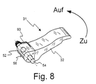
- Fig. 8
- ein für das erfindungsgemäße Elektrowerkzeug geeignetes Betätigungselement in einer perspektivischen Darstellung;
- Fig. 9a
- ein stark vereinfachter Längsschnitt durch eine andere Ausführung eines für die Erfindung geeigneten Betätigungselements, welches sich in der Spannstellung befindet;
- Fig. 9b
- das Betätigungselement aus Fig. 9a in Draufsicht;
- Fig. 10
- das Betätigungselement aus Fig. 9a in der Lösestellung.
- Fig. 1
- a simplified longitudinal section through an electric tool according to the invention in the region of its gear head, an actuating element for the quick-action clamping device being in the clamping position in which a tool is clamped in a rotationally fixed manner between a clamping flange and a counter flange;
- Fig. 2
- the power tool of Figure 1, in which the actuating element has been transferred into the release position, so that the tension between the clamping flange and the counter flange is released;
- Fig. 3
- the power tool of Figures 1 and 2, in which the clamping flange is completely unscrewed in the release position of the actuating element.
- Fig. 4
- a schematic longitudinal section through an eccentric cam with it when transferring the actuating element into the release position;
- Fig. 5
- a Fig. 4 corresponding representation, in which the actuating element is returned from the release into the clamping position;
- Fig. 6
- a view from behind of the eccentric of Figure 5, in which it can be seen that the eccentric is arranged offset in the direction of the eccentric axis of rotation to the cam.
- Fig. 7
- a development of an eccentric rolling surface;
- Fig. 8
- a suitable for the power tool according to the invention actuator in a perspective view;
- Fig. 9a
- a greatly simplified longitudinal section through another embodiment of an actuating element suitable for the invention, which is in the clamping position;
- Fig. 9b
- the actuating element of Figure 9a in plan view.
- Fig. 10
- the actuating element from Fig. 9a in the release position.
Ein erstes Ausführungsbeispiel für ein erfindungsgemäßes Elektrowerkzeug
in Form eines Winkelschleifers ist in Fig. 1 insgesamt
mit 10 bezeichnet. Innerhalb eines Gehäuses 12 des Elektrowerkzeugs
10 befindet sich eine Motor-/Getriebeeinheit 14,
die der Übersichtlichkeit halber gestrichelt dargestellt ist.
Die Motor-/Getriebeeinheit 14 weist einen Elektromotor 16 auf,
dessen Motorwelle 18 ein Ritzel 20 für ein Kegelradgetriebe
trägt. Ein Abtriebsrad 22 des Kegelradgetriebes ist drehfest
mit einer Hohlspindel 24 verbunden, die in - in Fig. 1 nicht
dargestellten - Kugellagern um eine Drehachse 25 drehbar gelagert
ist. An einem aus dem Gehäuse 12 nach außen hervorstehenden
Ende der Hohlspindel 24 ist ein Gegenflansch 26 ausgebildet,
dem ein Spannflansch 28 zum Einspannen eines Werkzeugs 30
zugeordnet ist. Bei dem Werkzeug 30 handelt es sich im dargestellten
Ausführungsbeispiel um eine Schleif- oder Trennscheibe.
Um ein manuelles Wechseln des Werkzeugs 30 zu ermöglichen,
ist eine Schnellspanneinrichtung vorgesehen, die unter anderem
den Gegenflansch 26, den Spannflansch 28 sowie ein Betätigungselement
31 mit einem Schwenkhebel 32 umfaßt. Durch Betätigen
des Betätigungselements 31 ist eine zwischen dem Gegenflansch
26 und dem Spannflansch 28 wirkende Verspannung aufhebbar.A first embodiment for a power tool according to the invention
in the form of an angle grinder is in total in Fig. 1
designated 10. Within a
Hierzu weist die Schnellspanneinrichtung ein koaxial in der
Hohlspindel 24 angeordnetes Druckstück 34 auf. Das Druckstück
34 hat annähernd die Form eines Bechers und ist mittels nicht
näher dargestellter Führungen drehfest, aber in axialer Richtung
beweglich in der Hohlspindel 24 geführt. Innenseitig ist
das Druckstück 34 mit einem Innengewinde 36 versehen, in das
ein Spannbolzen 40 mit einem Außengewinde 38 eingeschraubbar
ist. Der Spannbolzen 40 ist seinerseits fest mit dem Spannflansch
28 verbunden oder einstückig mit diesem ausgeführt. For this purpose, the quick release device has a coaxial in the
Die einen festen Sitz zwischen dem Gegenflansch 26 und dem
Spannflansch 28 hervorrufende Verspannung wird durch ein nur
schematisch angedeutetes Tellerfederpaket 42 aufgebaut, welches
auf der einen Seite an einem in der Hohlspindel 24 umlaufenden
Absatz 44 angreift. Auf der gegenüberliegenden Seite stützt
sich das Tellerfederpaket 42 an der Unterseite des Druckstücks
34 ab. Da die Oberseite des Druckstücks 34 an einem Sprengring
45 anschlägt, der in eine innenseitig in der Hohlspindel 24 umlaufenden
Nut 46 eingesetzt ist, kann die aus dem Druckstück
34, dem Spannbolzen 40 und dem Spannflansch 28 gebildete Einheit
nur gegen die Wirkung des Tellerfederpakets 42 in Richtung
der mit 48 bezeichneten Pfeile nach unten bewegt werden.The a tight fit between the
Ein Aufheben der durch das Tellerfederpaket 42 bewirkten Verspannung
ist nur mit Hilfe des Betätigungselements 31 möglich,
indem der daran ausgebildete Schwenkhebel 32 in der durch den
Pfeil 50 dargestellten Richtung von der in der Fig. 1 dargestellten
Spannstellung in eine in Fig. 2 dargestellte Lösestellung
überführt wird.A lifting of the tension caused by the
Der Schwenkhebel 32 ist fest mit einem Exzenter 52 verbunden,
der auf einer Welle 53 um eine Drehachse 54 drehbar gelagert
ist. Eine die Abrollfläche des Exzenters 52 bildende Lauffläche
56 greift an einen Nocken 58 an, der einstückig an einem Druckkopf
60 ausgebildet ist. Der Druckkopf 60 ist um die Drehachse
25 drehbar in einer selbstschmierenden Lagerhülse 62 axialbeweglich
aufgenommen. Mit Hilfe einer Spiraldruckfeder 64, die
zwischen einer Ringschulter 66 des Druckkopfs 60 sowie einem
Vorsprung 68 des Gehäuses 12 gehalten ist, wird der Druckkopf
60 gegen die Lauffläche 56 des Exzenters 52 gedrückt, so daß
der Druckkopf 60 stets in Kontakt mit dem Betätigungselement 31
steht.The
Die Funktion der erfindungsgemäßen Schnellspanneinrichtung wird nun anhand der Fig. 2 und 3 näher erläutert.The function of the quick release device according to the invention is now explained in more detail with reference to FIGS. 2 and 3.
Wird der Schwenkhebel 32 in Richtung des Pfeiles 50 umgelegt,
so drückt der Exzenter 52 über seine Lauffläche 56 den Nocken
58 infolge der Exzentrizität nach unten. Dadurch bewegt sich
der Druckkopf 60 insgesamt abwärts, und zwar entgegen der Wirkung
der Spiralfeder 64. Etwa nach der Hälfte des Schwenkweges
des Betätigungselements 31 berührt das untere konisch zulaufende
Ende des Druckkopfes 60 eine drehfest zur Hohlspindel auf
der axialen Oberseite des Druckstücks 34 befestigte Reibplatte
69.If the
Wird nun der Schwenkhebel 32 weiter zur Lösestellung hin verschwenkt,
so setzt sich die Abwärtsbewegung des Druckkopfes 60
fort, der nun das Druckstück 34 entgegen der Wirkung des Tellerfederpakets
42 nach unten in Richtung der Pfeile 48 drückt.
Um die gleiche Strecke wird auch der in das Druckstück 34 eingeschraubte
Spannflansch 28 nach unten bewegt. Dadurch entsteht
zwischen dem Spannflansch 28 und dem Werkzeug 30 ein kleiner
Spalt 70, der anzeigt, daß die Verspannung zwischen dem Gegenflansch
26 und dem Spannflansch 28 nunmehr aufgehoben ist. Dieser
Zustand ist in Fig. 2 dargestellt.If the
In diesem entspannten Zustand wirken keine nennenswerten Reibungskräfte
mehr zwischen dem Werkzeug 30 und dem Spannflansch
28. Der Spannflansch 28 läßt sich daher in dieser Position von
Hand aus dem Druckstück 34 herausschrauben, wie dies in Fig. 3
durch den Pfeil 71 angedeutet ist. Um das Herausschrauben zu
erleichtern, ist der Spannflansch umfangsseitig mit einer Rändelung
72 versehen.In this relaxed state there are no significant frictional forces
more between the
Bei der in den Fig. 1 bis 3 gezeigten Ausführung liegt der
Spannflansch 28 nicht unmittelbar auf dem Werkzeug 30 auf.
Vielmehr ist auf der aus dem Spannflansch 28 und dem Spannbolzen
40 gebildeten Einheit ein Zwischenflansch 74 drehbar aufgenommen,
der aus einer dünnen Scheibe 76 und einem von der Mitte
der Scheibe 76 axial hervorstehenden Ansatz 78 besteht. Durch
die Mitte der Scheibe 76 und des Ansatzes 78 verläuft eine zylindrische
Bohrung, durch die der Spannbolzen 40 geführt ist.
Außenseitig hat der Ansatz 78 die Form eines regelmäßigen Mehrkants.
Diese Mehrkantform findet ihre Entsprechung im Abschnitt
der Hohlspindel 24 unterhalb des Tellerfederpakets 42, der innenseitig
ebenfalls entsprechend mehrkantförmig ausgeführt ist.
Der Zwischenflansch 74 mit seinem Ansatz 78 läßt sich dadurch
so in diesen Abschnitt der Hohlspindel 24 einführen, daß ein
Formschluß zwischen der Hohlspindel 24 und dem Zwischenflansch
74 erzielt wird. Ein gegenseitiges Verdrehen von Hohlspindel 24
und Zwischenflansch 74 ist dann auch in der Lösestellung nicht
möglich.In the embodiment shown in FIGS. 1 to 3, the
Clamping
In der Spannstellung des Betätigungselements 31 ist das Werkzeug
30 zwischen dem Gegenflansch 26 und dem Spannflansch 28
eingespannt. Um eine formschlüssige Verbindung zwischen dem
Spannflansch 28 und dem Gegenflansch 26 in der Spannstellung zu
gewährleisten und somit ein Lösen des Spannflansches 28 unter
allen Betriebszuständen zu vermeiden, sind vorzugsweise die
einander zugewandten Flächen vom Spannflansch 28 und Zwischenflansch
76 zusätzlich mit Stirnverzahnungen o.ä. versehen. Somit
ergibt sich eine durchgehend formschlüssige Verbindung zwischen
dem Spannflansch 28 und der Hohlspindel 24. Folglich ist
es nicht möglich, daß sich der Spannflansch 28 zusammen mit dem
Spannbolzen 40 während der Benutzung des Elektrowerkzeugs durch
Verdrehen von alleine aus dem Druckstück 34 löst. Daher genügt
es auch, nach einem Wechseln des Werkzeugs den Spannflansch 28
nur leicht anzuziehen, bis der Spannflansch 28 am Zwischenflansch
76 anschlägt, da nach dem Verspannen der Spannflansch
28 in jedem Fall drehfest gehalten wird und die vom Tellerfederpaket
42 ausgeübte Verspannung praktisch unabhängig davon
ist, wie weit der Spannbolzen 40 in das Druckstück 34 eingeschraubt
ist.The tool is in the clamping position of the
Da sich der Spannflansch 28 nach Lösen der Verspannung gegenüber
dem Zwischenflansch 76 ohne weiteres verdrehen läßt, kann
der Spannbolzen 40 aus dem Druckstück 34 herausgeschraubt werden,
auch wenn der Zwischenflansch 74 noch mit seinem Ansatz 78
in der Hohlspindel 24 drehfest gehalten wird. Ein am Spannbolzen
40 aufgesetzter Sprengring 80 führt beim Herausschrauben
des Spannbolzens 40 der Zwischenflansch 74 mit, bis dieser
schließlich die in Fig. 3 gezeigte Position erreicht. Der
Spannflansch 28 kann nun, zusammen mit dem Zwischenflansch 74
und dem Spannbolzen 40, vollständig in Richtung der Pfeile 48
herausgezogen werden, wodurch das Werkzeug 30 vom Gegenflansch
26 abgenommen und gegen ein neues Werkzeug ausgetauscht werden
kann. Der Zusammenbau erfolgt in umgekehrter Reihenfolge.Since the clamping
Bei der erfindungsgemäßen Schnellspanneinrichtung wirkt nun der
Exzenter 52 derart mit dem Nocken 58 zusammen, daß dann, wenn
sich das Betätigungselement 31 in der in den Fig. 2 und 3 dargestellten
Lösestellung befindet, das Betätigungselement 31
selbsttätig wieder in Richtung auf die Spannstellung zurückgeführt
wird, sobald der Motor 16 des Elektrowerkzeugs 10 in Gang
gesetzt wird. Da in der Lösestellung der Druckkopf 60 an das
Druckstück 34 angepreßt ist, überträgt sich bei einem unbeabsichtigten
Einschalten des Motors 16 eine Bewegung der Hohlspindel
24 über einen bestehenden Reibschluß auf das daran
drehfest angeordnete Druckstück 34 und damit auf den Druckkopf
60 und den daran ausgebildeten Nocken 58. Die dadurch hervorgerufene
Rotation des Druckkopfes 60 führt dazu, daß die Haftreibung,
die zwischen dem Nocken 58 und der am Exzenter 52 ausgebildeten
Lauffläche 56 wirkt, in eine wesentlich geringere
Gleitreibung übergeht. Während die bei stillstehendem Druckkopf
60 wirkende Haftreibung das Betätigungselement 31 in der Lösestellung
festgehielt, überwiegt nun das Drehmoment, welches der
unter dem Druck des Tellerfederpakets 42 stehende Druckkopf 60
über den Nocken 58 auf den Exzenter 52 ausübt, das entgegengesetzt
wirkende Drehmoment, welches durch die Gleitreibung erzeugt
wird. Der Exzenter 52 beginnt sich daher zusammen mit dem
Schwenkhebel 32 in die durch den gestrichelten Pfeil 82 angedeutete
Richtung zurück zur Spannstellung zu bewegen.In the quick release device according to the invention, the
Die Vorgänge, die zwischen dem Nocken 58 und dem Exzenter 52
wirken, werden im folgenden anhand der Fig. 4 und 5 näher erläutert.The processes that take place between the
Die Fig. 4 zeigt in durchgezogenen Linien den Exzenter 52 sowie
den am Druckstück 60 ausgebildeten Nocken 58 in der in Fig. 1
gezeigten Spannstellung. Der Schwenkhebel 32 ist der Übersicht
halber nicht dargestellt. Die Lauffläche 56 des Exzenters 52
beschreibt bei dem in Fig. 4 dargestellten Ausführungsbeispiel
die Form eines Kreisbogens. Die mit e bezeichnete Exzentrizität,
d.h. der vertikale Abstand zwischen dem Mittelpunkt 55 des
Kreisbogens und der Drehachse 54 des Exzenters 52 in der Spannstellung,
bestimmt das Maß, um das bei einer Drehung des Exzenters
52 der Nocken 58 nach unten gedrückt wird. Bei einer Drehung
des Exzenters 52 um 180° beträgt dieses Maß 2e.4 shows the eccentric 52 and in solid lines
the
Gestrichelt dargestellt ist in Fig. 4 der Exzenter 52 bei einer
Drehung um ca. 45° zur Lösestellung hin. Dabei ist erkennbar,
wie sich die Lauffläche 56 des Exzenters 52 nach unten bewegt
und den Nocken 58 in die gestrichelt dargestellte Position
überführt. Der Druckkopf 60 bewegt sich daher in die durch den
Pfeil 82 angedeutete Richtung nach unten.4 shows the eccentric 52 at one
Turn through approx. 45 ° to the release position. It can be seen
how the
Fig. 5 zeigt mit durchgezogenen Linien den Exzenter 52 in der
Lösestellung. Da der Druckkopf 60 vom Tellerfederpaket 42 in
der durch den Pfeil 84 angedeuteten Richtung nach oben gedrückt
wird, wirkt auf den Exzenter 52 ein Drehmoment, welches ihn in
Richtung des Pfeiles 86 in die Spannstellung überführen möchte.
Dieses Drehmoment entsteht deswegen, weil der Nocken 58 auf den
Exzenter 52 eine Kraft ausübt, die nicht zentral zur Drehachse
Exzenters 52 hin gerichtet ist. Vielmehr besteht zwischen der
Berührlinie, entlang derer sich der Exzenter 52 und der Nocken
58 berühren, und der Drehachse 54 des Exzenters ein Versatz v.
Durch diesen Versatz v entsteht ein Hebelarm, der zu dem angesprochenen
Drehmoment führt. Bei dem vorstehend beschriebenen
Ausführungsbeispiel beträgt der Kreisbogendurchmesser 12,6 mm,
die Exzentrizität e 1,2 mm und der Versatz v 0,2 mm.Fig. 5 shows with solid lines the eccentric 52 in the
Release position. Since the
Solange der Druckkopf 60 mit dem Nocken 58 ruht, bewirkt die
zwischen der Lauffläche 56 des Exzenters 52 und der Oberseite
des Nockens 58 wirkende Haftreibung, daß der Exzenter 52 und
damit das gesamte Betätigungselement 31 trotz des wirkenden
Drehmomentes in seiner Lösestellung verharrt.As long as the
Wird jedoch nun durch eine Betätigung des Motors der Druckkopf
60 zusammen mit dem Nocken 58 in eine Rotation versetzt, so
geht die Haftreibung zwischen der Lauffläche 56 und dem Nocken
58 in eine Gleitreibung über. Wenn der Nocken 58 und die Lauffläche
56 aus gehärtetem geschliffenem Stahl gefertigt sind, so
ist die Gleitreibung um etwa eine Größenordnung geringer als
die Haftreibung. Die Reibung reicht nun nicht mehr dafür aus,
dem vom Druckkopf ausgeübten Drehmoment entgegenzuwirken, so
daß sich der Exzenter 52 in die durch den Pfeil 86 angedeutete
Richtung zurück in Richtung auf die Spannstellung bewegt.However, when the motor is actuated, the print head becomes
60 rotated together with the
Ein um etwa 60° zurückgeführter Exzenter 52 ist in Fig. 5 gestrichelt
angedeutet. Dabei ist erkennbar, daß der sich nun in
Richtung des Pfeiles 84 nach oben bewegende Druckkopf 60 über
den daran ausgebildeten Nocken 58 weiterhin ein Drehmoment auf
den Exzenter 52 ausübt, so daß das Betätigungselement 31 zunehmend
beschleunigt, bis es schließlich wieder in die in Fig. 4
dargestellte Spannposition (oder in eine Position kurz davor)
überführt ist.An eccentric 52 which is returned by approximately 60 ° is dashed in FIG. 5
indicated. It can be seen that the now
In the direction of
Fig. 6 zeigt eine Ansicht von hinten auf den Exzenter 52, in
der erkennbar ist, daß der Exzenter 52 in Richtung der Drehachse
54 des Exzenters versetzt zum Nocken 58 angeordnet ist. Die
Größe dieses Versatzes ist gleich dem Abstand zwischen der Mittelebene
57 des Exzenters 52 und der Drehachse 25 des Nockens
58. Aufgrund dieses Versatzes ist die Berührlinie zwischen Exzenter
52 und Nocken 58 nicht mehr symmetrisch zur Drehachse 25
des Nockens 58 angeordnet. Bei einer Drehung des Nockens 58
wird dadurch ein zusätzliches Drehmoment auf den Exzenter 52
ausgeübt, dessen Richtung davon abhängt, ob sich der Nocken 58
im oder gegen den Uhrzeigersinn um seine Längsachse 25 dreht.
Bei dem dargestellten Ausführungsbeispiel dreht sich der Nocken
58 in der durch den Pfeil 59 angedeuteten Richtung, wodurch der
Exzenter 52 in Richtung des Pfeiles 61 um seine Längsachse 54
zurück zur Spannstellung hin bewegt wird.Fig. 6 shows a rear view of the eccentric 52, in
which can be seen that the eccentric 52 in the direction of the axis of
Eine ähnliche Wirkung wird im übrigen auch erzeugt, wenn der
Exzenter 52, in Richtung der Drehachse 54 gesehen, leicht konisch
geformt ist. Dadurch wird ebenfalls erreicht, daß die Berührlinie
zwischen dem Exzenter 52 und dem Nocken 58, die sich
in diesem Falle annähernd zu einem Berührpunkt verkürzt, nicht
mehr symmetrisch zur Drehachse 25 des Nockens 58 angeordnet
ist. Die Konizität des Exzenters 52 kann dabei Werte von etwa
0,1° bis 1°, vorzugsweise von etwa 0,3°, annehmen.A similar effect is also produced when the
Vorzugsweise bestehen sowohl der Exzenter 52 als auch der
Druckbolzen 60 mit dem Nocken 58 aus gesinterten rollierten
Stahlteilen, deren Vickershärte im Bereich von etwa 64 und deren
Rauhtiefe Rz im Bereich von etwa 2 µm liegt. Dies hat, wie
oben bereits angeführt, den Vorteil, daß dadurch eine besonders
große Differenz zwischen der Haft- und der Gleitreibung entsteht.
Außerdem ist aufgrund der großen Härte der Verschleiß
gering, so daß die für das Zurückführen des Betätigungselements
31 maßgebenden Reibungsverhältnisse zwischen Nocken 58 und
Lauffläche 56, zum anderen auch der beim Umschwenken des Spannhebels
32 erzeugte Hub des Druckbolzens 60 im Laufe der Zeit
konstant bleiben. Bei derartigen Stahlflächen beträgt, wenn das
Tellerfederpaket 42 eine Druckkraft von ca. 3.000 N erzeugt,
die Haftreibungskraft ca. 300 N und die Gleitreibungskraft ca.
40 N.Both the eccentric 52 and the
Um das auf den Exzenter 52 wirkende Drehmoment während des Zurückschwenkens in die Spannstellung beeinflussen zu können, kann anstelle eines Exzenters mit kreisbogenförmiger Lauffläche ein Exzenter verwendet werden, dessen Lauffläche keine konstante Steigung aufweist.To the torque acting on the eccentric 52 during the To be able to influence swinging back into the clamping position can instead of an eccentric with an arc-shaped tread an eccentric can be used, the tread of which is not constant Has slope.
In Fig. 7 ist eine Abrollfläche eines derartigen modifizierten
Exzenters über dem Schwenkwinkel α aufgetragen. Darin ist erkennbar,
daß die Steigung α2 der Abrollfläche bei großen
Schwenkwinkeln (Lösestellung) kleiner ist als die Steigung α1
der Abrollfläche bei kleineren Schwenkwinkeln (Spannstellung).
Diese Gestaltung der Abrollfläche bewirkt, daß sich das Betätigungselement
31 nach dem Einschalten des Motors in der Lösestellung
zunächst langsam aus dieser entfernt und dann stärker
beschleunigt. Falls gewünscht, kann die Endgeschwindigkeit dabei
so groß sein, daß das Betätigungselement 31 schließlich unter
Überwindung eines Einrastwiderstands in eine Endlage übergeht,
in der es in einer Aussparung im Gehäuse 12 des Elektrowerkzeugs
10 versenkt ist. Bei größeren Einrastwiderständen
kann dies jedoch unzweckmäßig sein, da dies evtl. eine so große
Beschleunigung des Betätigungselements 31 erfordert, daß eine
Gefährdung des Benutzers beim Zurückschwenken nicht völlig ausgeschlossen
werden kann.7, a rolling surface of such a modified eccentric is plotted over the swivel angle α. This shows that the gradient α 2 of the rolling surface at large swivel angles (release position) is smaller than the gradient α 1 of the rolling surface at smaller swivel angles (clamping position). This design of the rolling surface causes the
Auf die Geschwindigkeit beim selbsttätigen Zurückschwenken des
Betätigungselements 31 kann auch durch einen Wechsel der Oberflächenbeschaffenheit
der Lauffläche 56 Einfluß genommen werden.
So kann beispielsweise vorgesehen sein, daß die Lauffläche
zwischen einem Schwenkwinkel von 0° und 60° (von der Spannstellung
gesehen, siehe Fig. 7) derart aufgeraut ist, daß aufgrund
der dort größeren Gleitreibung die selbsttätige Zurückschwenkbewegung
des Betätigungselements 31 gebremst oder zumindest einer
weiteren Beschleunigung entgegengewirkt wird.On the speed when swiveling the
Actuator 31 can also by changing the surface quality
the
Bei dem in den Fig. 1 bis 3 dargestellten Ausführungsbeispiel
ist der Nocken 58 an einem Druckkopf 60 ausgebildet, der erst
im Verlauf des Verschwenkens des Betätigungselements 31 an dem
Druckstück 34 angreift. Alternativ hierzu kann auch vorgesehen
sein, daß der Exzenter 52 unmittelbar an dem Druckstück 34 angreift.
Dieses ist dann so auszuführen, daß es nach oben aus
der Hohlspindel 24 hinausragt. Auf dem Druckstück 34 kann zusätzlich
ein Nocken 58 ausgebildet sein. Der Nocken 58 kann
aber hier ebenso wie bei dem oben erläuterten Ausführungsbeispiel
in dem Sinne entfallen, daß das gesamte Druckstück 34
bzw. der Druckkopf 60 als Nocken angesehen wird.In the embodiment shown in FIGS. 1 to 3
the
Um bei diesem alternativen Ausführungsbeispiel auch in der
Spannstellung des Betätigungselements 31 eine fortwährende Reibung
zwischen dem Druckstück 34 und der am Exzenter 52 ausgebildeten
Lauffläche 56 zu verhindern, sollte in der Spannstellung
zwischen dem Exzenter 52 und dem Druckstück 34 ein kleiner
Spalt verbleiben. Als Ersatz für die Wirkung der Spiralfeder 64
kann dann eine am Betätigungselement 31 angreifende Rückholfeder
92 vorgesehen sein, wie dies in Fig. 8 dargestellt ist. Die
Rückholfeder 92 beaufschlagt das Betätigungselement 31 bereits
in seiner Spannstellung mit einer geringen Federkraft und sorgt
für den notwendigen Abstand zum Druckstück 34.To in this alternative embodiment also in the
Clamping position of the actuator 31 a constant friction
between the
Denkbar ist schließlich auch, anstelle eines Schwenkhebels einen Drehhebel zu verwenden, wie dies in der eingangs erwähnten EP 0 152 564 A2 beschrieben ist. Die sich in der Lösestellung einander berührenden Flächen des Drehhebels und des Druckstücks (bzw. eines daran angreifenden Druckkopfes) sowie die Steigung des Gewindes, über das der Drehhebel mit dem Gehäuse verschraubt ist, sind dann so auszulegen, daß bei Betätigen des Motors der Drehhebel gerade nicht durch eine reibschlüssig von dem Druckstück auf den Drehhebel übertragene Kraft in Bewegung gesetzt wird. Vielmehr sind die angesprochenen Parameter so festzulegen, daß bei einer Rotation des Druckstücks die Reibung an der Kontaktfläche abnimmt, so daß der Drehhebel ausschließlich unter der Wirkung der elastischen Andrückelemente aus dem Gewinde herausgedreht wird und dadurch in seine Spannposition zurückgeführt wird. Auf diese Weise läßt sich der Drehhebel wesentlich kontrollierter in die Spannstellung zurückführen, als wenn dieser unmittelbar über einen Reibschluß vom Motor angetrieben wird.Finally, it is also conceivable instead of a swivel lever to use a rotary lever, as mentioned in the introduction EP 0 152 564 A2 is described. Which is in the release position mutually contacting surfaces of the rotary lever and the pressure piece (or a print head attacking it) and the Pitch of the thread over which the rotary lever with the housing is screwed, are then to be designed so that when the Motors of the rotary lever just not through a frictional force transmitted to the thrust piece on the rotary lever in motion is set. Rather, the parameters addressed are like this to determine that with a rotation of the pressure piece, the friction decreases at the contact surface, so that the rotary lever exclusively under the action of the elastic pressing elements from the Thread is unscrewed and thereby into its clamping position is returned. In this way, the rotary lever can be significantly return to the clamping position in a more controlled manner than if this is driven directly by the motor via a frictional connection becomes.
In den Fig. 9a, 9b und 10 ist ein alternatives Ausführungsbeispiel
für ein Betätigungselement 31 schematisch dargestellt.
Anstelle eines mit einem Exzenter verbundenen Schwenkhebels
wird hier als Betätigungselement ein Schieber 100 verwendet,
dessen abgeschrägte Unterseite eine Lauffläche 102 bildet, die
mit einem Druckkopf 104 zusammenwirkt. Anders als der oben
beschriebene Druckkopf 60 weist der Druckkopf 104 eine abgerundete
Oberseite 106 auf, so daß der Druckkopf 104 insgesamt als
Nocken wirkt. Der mit einem Durchgriff 108 versehene Schieber
100 ist derart zwischen zwei nur schematisch angedeuteten
Führungen 110, 112 geführt, daß er sich in der durch den Pfeil
116 angedeuteten Richtung verschieben läßt. In Fig. 9a befindet
sich der Schieber 100, der in Fig. 9b in Draufsicht gezeigt
ist, in der Spannstellung. Wird er nun durch Ziehen am Durchgriff
108 in Richtung des Pfeiles 116 verschoben, so drückt die
Lauffläche 102 an der Unterseite des Schiebers 100 den (ohne
Führung dargestellten) Druckkopf 104 in Richtung des Pfeiles
114 nach unten. Dadurch wird schließlich die Verspannung
zwischen dem Spannflansch 28 und dem Gegenflansch 26 aufgehoben,
wie dies oben mit Bezug auf die Fig. 1 bis 3 ausführlich
beschrieben wurde.9a, 9b and 10 is an alternative embodiment
schematically shown for an
In Fig. 10 befindet sich der Schieber 100 in der Lösestellung.
Wird nun der Druckkopf 60 in Rotation versetzt, so verringert
sich, wie dies oben bereits geschildert wurde, die zwischen der
Oberseite 106 des Druckkopfes 60 und der Lauffläche 102 des
Schiebers 100 wirkende Reibungskraft, wodurch der Druckkopf 60
nunmehr den Schieber 100 wieder zurück in die Spannstellung zu
schieben vermag, wie dies durch den Pfeil 118 angedeutet ist.
Auch hier kann die Lauffläche 102 selbstverständlich unterschiedliche
Steigungen aufweisen, wie dies oben zu Fig. 7 beschrieben
wurde.10, the
Claims (13)
Applications Claiming Priority (2)
| Application Number | Priority Date | Filing Date | Title |
|---|---|---|---|
| DE10039739 | 2000-08-16 | ||
| DE10039739A DE10039739A1 (en) | 2000-08-16 | 2000-08-16 | Power tool with quick release device |
Publications (3)
| Publication Number | Publication Date |
|---|---|
| EP1180416A2 true EP1180416A2 (en) | 2002-02-20 |
| EP1180416A3 EP1180416A3 (en) | 2004-01-07 |
| EP1180416B1 EP1180416B1 (en) | 2005-06-08 |
Family
ID=7652415
Family Applications (1)
| Application Number | Title | Priority Date | Filing Date |
|---|---|---|---|
| EP01119414A Expired - Lifetime EP1180416B1 (en) | 2000-08-16 | 2001-08-11 | Power tool with quick coupling means |
Country Status (4)
| Country | Link |
|---|---|
| US (1) | US6569001B2 (en) |
| EP (1) | EP1180416B1 (en) |
| AT (1) | ATE297292T1 (en) |
| DE (2) | DE10039739A1 (en) |
Cited By (14)
| Publication number | Priority date | Publication date | Assignee | Title |
|---|---|---|---|---|
| EP2213419A1 (en) * | 2009-01-30 | 2010-08-04 | C. & E. Fein GmbH | Hand-held power tool with tensioning device for a tool |
| EP2213416A2 (en) † | 2009-01-29 | 2010-08-04 | C. & E. Fein GmbH | Hand-held power tool with tensioning device for a tool |
| WO2012100894A1 (en) * | 2011-01-25 | 2012-08-02 | Robert Bosch Gmbh | Tool chucking device |
| DE202011110131U1 (en) * | 2011-06-06 | 2013-02-11 | Robert Bosch Gmbh | Hand machine tool fixture |
| CN103347653A (en) * | 2011-01-25 | 2013-10-09 | 罗伯特·博世有限公司 | Tool clamping fixture |
| WO2013156306A1 (en) * | 2012-04-17 | 2013-10-24 | C. & E. Fein Gmbh | Hand tool having a clamping device for a tool |
| EP2799188A4 (en) * | 2011-12-28 | 2015-08-12 | Positec Power Tools Suzhou Co | Power tool |
| CN106312954A (en) * | 2015-06-26 | 2017-01-11 | 苏州宝时得电动工具有限公司 | A handheld tool and a clamping device thereof |
| WO2018072996A1 (en) * | 2016-10-18 | 2018-04-26 | Robert Bosch Gmbh | Quick clamping device for at least one rotationally drivable drive shaft having a portable machine tool, in particular an angle grinding machine |
| CN108274435A (en) * | 2017-01-06 | 2018-07-13 | 南京德朔实业有限公司 | Power tool |
| WO2019015980A1 (en) * | 2017-07-20 | 2019-01-24 | Robert Bosch Gmbh | Quick-clamping device for a portable machine tool |
| CN109877680A (en) * | 2019-03-27 | 2019-06-14 | 深圳市贝优通新能源技术开发有限公司 | A kind of polishing equipment of the high reliablity for construction |
| CN111761480A (en) * | 2020-03-30 | 2020-10-13 | 浙江博来工具有限公司 | Quick clamping device and angle mill with same |
| CZ308718B6 (en) * | 2020-06-29 | 2021-03-17 | Alexandr Filippov | Grinder for grinding skate blades |
Families Citing this family (63)
| Publication number | Priority date | Publication date | Assignee | Title |
|---|---|---|---|---|
| CN100534717C (en) * | 2004-07-08 | 2009-09-02 | 梅塔波沃克有限公司 | Rapid locking device |
| DE102004047280A1 (en) * | 2004-09-29 | 2006-04-06 | Hilti Ag | Tool device for the eccentric drive of a tool |
| US10369718B2 (en) | 2004-12-15 | 2019-08-06 | Canis Major Tool Company Llc | Flush cut saw |
| US9108334B2 (en) * | 2004-12-15 | 2015-08-18 | Canis Major Tool Company Llc | Flush cut saw |
| US8087977B2 (en) * | 2005-05-13 | 2012-01-03 | Black & Decker Inc. | Angle grinder |
| ATE389510T1 (en) | 2005-11-28 | 2008-04-15 | Metabowerke Gmbh | TOOL WITH QUICK CLAMPING DEVICE |
| AT503284B1 (en) * | 2006-03-21 | 2007-09-15 | Panhans Maschb Gmbh | CIRCULAR SAWING MACHINE WITH CLAMPING CIRCULAR FOR A CIRCULAR SAW BLADE |
| US8858301B2 (en) * | 2008-01-07 | 2014-10-14 | Lachlan George Reid | Attachment mechanism for a cutting disc |
| US8408974B2 (en) * | 2009-07-14 | 2013-04-02 | Black & Decker Inc. | Adapter for abrasive cutting wheels |
| USD619152S1 (en) | 2009-12-18 | 2010-07-06 | Techtronic Power Tools Technology Limited | Adapter |
| USD623034S1 (en) | 2009-12-18 | 2010-09-07 | Techtronic Power Tools Technology Limited | Tool arbor |
| CN102107386B (en) * | 2009-12-28 | 2014-01-01 | 泉峰(中国)贸易有限公司 | Sanding machine |
| CN102233537B (en) * | 2010-04-27 | 2015-03-11 | 南京德朔实业有限公司 | Hand-held power tool with quick clamping device for working element |
| US9073195B2 (en) | 2010-04-29 | 2015-07-07 | Black & Decker Inc. | Universal accessory for oscillating power tool |
| US9186770B2 (en) * | 2010-04-29 | 2015-11-17 | Black & Decker Inc. | Oscillating tool attachment feature |
| US8925931B2 (en) | 2010-04-29 | 2015-01-06 | Black & Decker Inc. | Oscillating tool |
| CN102416615B (en) * | 2010-09-26 | 2014-07-30 | 南京德朔实业有限公司 | Handhold power tool with operating element quick clamping device |
| USD651062S1 (en) | 2010-09-29 | 2011-12-27 | Milwaukee Electric Tool Corporation | Tool interface for an accessory |
| USD653523S1 (en) | 2010-09-29 | 2012-02-07 | Milwaukee Electric Tool Corporation | Adapter for a tool |
| USD646542S1 (en) | 2010-09-29 | 2011-10-11 | Milwaukee Electric Tool Corporation | Accessory interface for a tool |
| CN102441876B (en) * | 2010-10-09 | 2014-10-15 | 南京德朔实业有限公司 | Power tool with work element clamping device |
| US9149923B2 (en) | 2010-11-09 | 2015-10-06 | Black & Decker Inc. | Oscillating tools and accessories |
| CN102528768B (en) * | 2010-12-07 | 2014-10-15 | 南京德朔实业有限公司 | Power tool |
| US9174354B2 (en) | 2011-05-18 | 2015-11-03 | Chevron (Hk) Limited | Power tool |
| CN102785161B (en) * | 2011-05-18 | 2015-02-25 | 南京德朔实业有限公司 | Power tool |
| CN102259329B (en) * | 2011-06-22 | 2013-08-21 | 南京德朔实业有限公司 | Multifunctional electric power tool |
| EP3090839A1 (en) * | 2011-09-29 | 2016-11-09 | Positec Power Tools (Suzhou) Co., Ltd | Oscillatory power tool |
| US9067293B2 (en) | 2011-09-30 | 2015-06-30 | Robert Bosch Gmbh | Accessory clamp for a power tool |
| JP2013094904A (en) * | 2011-11-01 | 2013-05-20 | Makita Corp | Working tool |
| JP5746645B2 (en) | 2012-02-03 | 2015-07-08 | 株式会社マキタ | Work tools |
| JP2013244553A (en) * | 2012-05-24 | 2013-12-09 | Makita Corp | Work tool |
| USD832666S1 (en) | 2012-07-16 | 2018-11-06 | Black & Decker Inc. | Oscillating saw blade |
| US9486934B2 (en) * | 2012-11-23 | 2016-11-08 | Chervon (Hk) Limited | Accessory clamping mechanism and power tool having the same |
| US9339927B2 (en) * | 2012-12-29 | 2016-05-17 | Chervon (Hk) Limited | Accessory clamping mechanism and power tool having the same |
| US9956676B2 (en) * | 2013-01-09 | 2018-05-01 | Techtronic Power Tools Technology Limited | Tool with rotatable head |
| CN103111989B (en) * | 2013-01-30 | 2015-05-20 | 南京久驰机电实业有限公司 | Multifunctional handheld power tool |
| CN103963015B (en) * | 2013-02-05 | 2016-03-16 | 苏州宝时得电动工具有限公司 | Power tool |
| US9555554B2 (en) | 2013-05-06 | 2017-01-31 | Milwaukee Electric Tool Corporation | Oscillating multi-tool system |
| JP6287205B2 (en) * | 2013-12-27 | 2018-03-07 | 日立工機株式会社 | Power working machine |
| JP6400460B2 (en) * | 2014-01-30 | 2018-10-03 | 株式会社マキタ | Cutting machine |
| CN104057411A (en) * | 2014-06-28 | 2014-09-24 | 杨海蓉 | Clamping device |
| US9475172B2 (en) | 2014-07-15 | 2016-10-25 | Milwaukee Electric Tool Corporation | Adjustable guard for power tool |
| USD744800S1 (en) | 2014-07-16 | 2015-12-08 | Milwaukee Electric Tool Corporation | Power tool blade guard |
| WO2017036403A1 (en) * | 2015-08-31 | 2017-03-09 | 苏州宝时得电动工具有限公司 | Hand-held tool and clamping device thereof |
| US10011036B2 (en) * | 2015-11-09 | 2018-07-03 | Robert Bosch Tool Corporation | Blade and blade attachment system for an oscillating tool |
| EP3300835B1 (en) * | 2016-09-29 | 2021-05-12 | Black & Decker Inc. | Accessory clamp and spindle lock mechanism for power tool lock |
| US10265778B2 (en) | 2017-01-16 | 2019-04-23 | Black & Decker Inc. | Accessories for oscillating power tools |
| USD814900S1 (en) | 2017-01-16 | 2018-04-10 | Black & Decker Inc. | Blade for oscillating power tools |
| US10818450B2 (en) | 2017-06-14 | 2020-10-27 | Black & Decker Inc. | Paddle switch |
| DE102017214117A1 (en) * | 2017-08-11 | 2019-02-14 | Robert Bosch Gmbh | Quick clamping device |
| DE102017214118A1 (en) * | 2017-08-11 | 2019-02-14 | Robert Bosch Gmbh | Quick-clamping device for a, in particular at least one rotatably driven output shaft having, portable machine tool, in particular angle grinder |
| CN109986513A (en) * | 2017-12-29 | 2019-07-09 | 宝时得科技(中国)有限公司 | Power tool |
| JP7096032B2 (en) | 2018-03-28 | 2022-07-05 | 株式会社マキタ | Multi tool |
| JP7123633B2 (en) * | 2018-06-01 | 2022-08-23 | 株式会社マキタ | Work tools |
| WO2020081906A1 (en) * | 2018-10-19 | 2020-04-23 | Saint-Gobain Abrasives, Inc. | Grinding wheel assembly |
| US11052475B2 (en) * | 2018-11-27 | 2021-07-06 | Zhejiang Burley Tools Co., Ltd. | Rapid replacing structure for multi-purpose saw |
| DE102019131292A1 (en) * | 2019-11-20 | 2021-05-20 | Metabowerke Gmbh | Device for clamping a machining tool in an electric hand tool device |
| US11590593B2 (en) | 2019-11-28 | 2023-02-28 | Makita Corporation | Power tool |
| US11660690B2 (en) | 2019-11-28 | 2023-05-30 | Makita Corporation | Power tool |
| JP7422538B2 (en) | 2019-12-26 | 2024-01-26 | 株式会社マキタ | Work tools |
| JP7330914B2 (en) | 2020-02-13 | 2023-08-22 | 株式会社マキタ | vibration tool |
| CN111941311A (en) * | 2020-07-24 | 2020-11-17 | 中国航空工业集团公司沈阳飞机设计研究所 | Clamping and fixing structure |
| CN114905465B (en) * | 2021-02-10 | 2023-09-12 | 苏州宝时得电动工具有限公司 | Fastening mechanism and power tool |
Citations (4)
| Publication number | Priority date | Publication date | Assignee | Title |
|---|---|---|---|---|
| EP0152564A2 (en) * | 1984-02-18 | 1985-08-28 | C. & E. FEIN GmbH & Co. | Tool mounting |
| DE3523746A1 (en) * | 1985-07-03 | 1987-01-08 | Metabowerke Kg | Quick-action clamping device for rotating disc-shaped tools |
| EP0319813A2 (en) * | 1987-12-08 | 1989-06-14 | C. & E. FEIN GmbH & Co. | Hand power tool using automatic locking of the working spindle |
| EP0650805A1 (en) * | 1993-10-27 | 1995-05-03 | C. & E. FEIN GmbH & Co. | Electric power tool |
Family Cites Families (1)
| Publication number | Priority date | Publication date | Assignee | Title |
|---|---|---|---|---|
| EP0495181B1 (en) * | 1991-01-16 | 1994-04-13 | C. & E. FEIN GmbH & Co. | Grinding power tool with quick coupling means |
-
2000
- 2000-08-16 DE DE10039739A patent/DE10039739A1/en not_active Withdrawn
-
2001
- 2001-08-11 DE DE50106436T patent/DE50106436D1/en not_active Expired - Lifetime
- 2001-08-11 AT AT01119414T patent/ATE297292T1/en not_active IP Right Cessation
- 2001-08-11 EP EP01119414A patent/EP1180416B1/en not_active Expired - Lifetime
- 2001-08-16 US US09/931,706 patent/US6569001B2/en not_active Expired - Lifetime
Patent Citations (4)
| Publication number | Priority date | Publication date | Assignee | Title |
|---|---|---|---|---|
| EP0152564A2 (en) * | 1984-02-18 | 1985-08-28 | C. & E. FEIN GmbH & Co. | Tool mounting |
| DE3523746A1 (en) * | 1985-07-03 | 1987-01-08 | Metabowerke Kg | Quick-action clamping device for rotating disc-shaped tools |
| EP0319813A2 (en) * | 1987-12-08 | 1989-06-14 | C. & E. FEIN GmbH & Co. | Hand power tool using automatic locking of the working spindle |
| EP0650805A1 (en) * | 1993-10-27 | 1995-05-03 | C. & E. FEIN GmbH & Co. | Electric power tool |
Cited By (26)
| Publication number | Priority date | Publication date | Assignee | Title |
|---|---|---|---|---|
| EP2213416B1 (en) * | 2009-01-29 | 2015-10-28 | C. & E. Fein GmbH | Hand-held power tool with tensioning device for a tool |
| EP2213416A2 (en) † | 2009-01-29 | 2010-08-04 | C. & E. Fein GmbH | Hand-held power tool with tensioning device for a tool |
| EP2213419A1 (en) * | 2009-01-30 | 2010-08-04 | C. & E. Fein GmbH | Hand-held power tool with tensioning device for a tool |
| US8317574B2 (en) | 2009-01-30 | 2012-11-27 | C. & E. Fein Gmbh | Power-driven hand tool with clamping fixture for a tool |
| US9463547B2 (en) | 2011-01-25 | 2016-10-11 | Robert Bosch Gmbh | Tool chucking device |
| CN103347653A (en) * | 2011-01-25 | 2013-10-09 | 罗伯特·博世有限公司 | Tool clamping fixture |
| RU2601716C2 (en) * | 2011-01-25 | 2016-11-10 | Роберт Бош Гмбх | Tool chucking device |
| WO2012100894A1 (en) * | 2011-01-25 | 2012-08-02 | Robert Bosch Gmbh | Tool chucking device |
| DE202011110131U1 (en) * | 2011-06-06 | 2013-02-11 | Robert Bosch Gmbh | Hand machine tool fixture |
| US9486909B2 (en) | 2011-06-06 | 2016-11-08 | Robert Bosch Gmbh | Clamping device for a hand-held power tool |
| EP2799188A4 (en) * | 2011-12-28 | 2015-08-12 | Positec Power Tools Suzhou Co | Power tool |
| US9821430B2 (en) | 2011-12-28 | 2017-11-21 | Positec Power Tools (Suzhou) Co., Ltd. | Power tools |
| WO2013156306A1 (en) * | 2012-04-17 | 2013-10-24 | C. & E. Fein Gmbh | Hand tool having a clamping device for a tool |
| CN106312954A (en) * | 2015-06-26 | 2017-01-11 | 苏州宝时得电动工具有限公司 | A handheld tool and a clamping device thereof |
| CN106312954B (en) * | 2015-06-26 | 2021-08-10 | 苏州宝时得电动工具有限公司 | Hand-held tool and clamping device thereof |
| WO2018072996A1 (en) * | 2016-10-18 | 2018-04-26 | Robert Bosch Gmbh | Quick clamping device for at least one rotationally drivable drive shaft having a portable machine tool, in particular an angle grinding machine |
| KR20190071710A (en) * | 2016-10-18 | 2019-06-24 | 로베르트 보쉬 게엠베하 | A portable power tool having at least one rotatably driveable output shaft, particularly a quick-clamping device for angle grinders |
| US11607772B2 (en) | 2016-10-18 | 2023-03-21 | Robert Bosch Gmbh | Quick clamping device for at least one rotationally drivable drive shaft having a portable machine tool, in particular an angle grinding machine |
| CN108274435A (en) * | 2017-01-06 | 2018-07-13 | 南京德朔实业有限公司 | Power tool |
| CN108274435B (en) * | 2017-01-06 | 2020-12-01 | 南京德朔实业有限公司 | Power tool |
| WO2019015980A1 (en) * | 2017-07-20 | 2019-01-24 | Robert Bosch Gmbh | Quick-clamping device for a portable machine tool |
| US11717935B2 (en) | 2017-07-20 | 2023-08-08 | Robert Bosch Gmbh | Quick-clamping device for a portable machine tool |
| CN109877680A (en) * | 2019-03-27 | 2019-06-14 | 深圳市贝优通新能源技术开发有限公司 | A kind of polishing equipment of the high reliablity for construction |
| CN111761480A (en) * | 2020-03-30 | 2020-10-13 | 浙江博来工具有限公司 | Quick clamping device and angle mill with same |
| CN111761480B (en) * | 2020-03-30 | 2021-10-29 | 浙江博来工具有限公司 | Quick clamping device and angle mill with same |
| CZ308718B6 (en) * | 2020-06-29 | 2021-03-17 | Alexandr Filippov | Grinder for grinding skate blades |
Also Published As
| Publication number | Publication date |
|---|---|
| US20020028644A1 (en) | 2002-03-07 |
| DE50106436D1 (en) | 2005-07-14 |
| EP1180416A3 (en) | 2004-01-07 |
| ATE297292T1 (en) | 2005-06-15 |
| DE10039739A1 (en) | 2002-02-28 |
| EP1180416B1 (en) | 2005-06-08 |
| US6569001B2 (en) | 2003-05-27 |
Similar Documents
| Publication | Publication Date | Title |
|---|---|---|
| EP1180416B1 (en) | Power tool with quick coupling means | |
| DE2741166C2 (en) | Device for actuating a clamping head | |
| DE3610569C2 (en) | Disc brake for vehicles | |
| DE3205141C2 (en) | ||
| EP2142042B1 (en) | Connection means and method for connecting a first component and a second component | |
| EP3177839B1 (en) | Bolt for bracing parts lying on one another | |
| DE3727147A1 (en) | TENSIONING DRILL CHUCK | |
| EP2178675A1 (en) | Quick-change system | |
| EP0577981B1 (en) | Head for a medical or dental handpiece comprising an oscillating treatment tool | |
| DE1477405C3 (en) | Adjustment device for tool carriers, in particular for boring bars for precision boring machines with a rotatable boring spindle | |
| DE2841116C2 (en) | Device for pulling off sleeves, bearing rings or the like. | |
| DE19508091C1 (en) | Punch unit with catch releasably supported on rear of guide bushing | |
| DE19701049C1 (en) | Radial roller head | |
| EP0256289B1 (en) | Device for setting fasteners or bolts | |
| DE2116233A1 (en) | Press smoothing machine | |
| DE3724232C2 (en) | ||
| EP3658318B1 (en) | Cutting tool having an adjusting device | |
| DE2339038C2 (en) | Device for thread chasing on a lathe | |
| DE1954337B2 (en) | Roller burnishing tool for cylindrical workpiece surfaces | |
| DE2702211A1 (en) | STEERING PULLEY | |
| DE1959770C3 (en) | Tapping chucks | |
| DE655217C (en) | Cock, the peg of which is lifted from the seat by turning the operating handle by means of a thread before the opening movement or pressed back onto the seat after the closing movement | |
| DE102018212422A1 (en) | Magnetic formwork device | |
| DE4025745C2 (en) | ||
| DE1506473B1 (en) | Safety catch for construction and similar elevators |
Legal Events
| Date | Code | Title | Description |
|---|---|---|---|
| PUAI | Public reference made under article 153(3) epc to a published international application that has entered the european phase |
Free format text: ORIGINAL CODE: 0009012 |
|
| AK | Designated contracting states |
Kind code of ref document: A2 Designated state(s): AT BE CH CY DE DK ES FI FR GB GR IE IT LI LU MC NL PT SE TR |
|
| AX | Request for extension of the european patent |
Free format text: AL;LT;LV;MK;RO;SI |
|
| PUAL | Search report despatched |
Free format text: ORIGINAL CODE: 0009013 |
|
| AK | Designated contracting states |
Kind code of ref document: A3 Designated state(s): AT BE CH CY DE DK ES FI FR GB GR IE IT LI LU MC NL PT SE TR |
|
| AX | Request for extension of the european patent |
Extension state: AL LT LV MK RO SI |
|
| RAP1 | Party data changed (applicant data changed or rights of an application transferred) |
Owner name: C. & E. FEIN GMBH |
|
| 17P | Request for examination filed |
Effective date: 20040608 |
|
| AKX | Designation fees paid |
Designated state(s): AT BE CH CY DE DK ES FI FR GB GR IE IT LI LU MC NL PT SE TR |
|
| RAP1 | Party data changed (applicant data changed or rights of an application transferred) |
Owner name: C. & E. FEIN GMBH |
|
| GRAP | Despatch of communication of intention to grant a patent |
Free format text: ORIGINAL CODE: EPIDOSNIGR1 |
|
| GRAS | Grant fee paid |
Free format text: ORIGINAL CODE: EPIDOSNIGR3 |
|
| GRAA | (expected) grant |
Free format text: ORIGINAL CODE: 0009210 |
|
| AK | Designated contracting states |
Kind code of ref document: B1 Designated state(s): AT BE CH CY DE DK ES FI FR GB GR IE IT LI LU MC NL PT SE TR |
|
| PG25 | Lapsed in a contracting state [announced via postgrant information from national office to epo] |
Ref country code: TR Free format text: LAPSE BECAUSE OF FAILURE TO SUBMIT A TRANSLATION OF THE DESCRIPTION OR TO PAY THE FEE WITHIN THE PRESCRIBED TIME-LIMIT Effective date: 20050608 Ref country code: IE Free format text: LAPSE BECAUSE OF FAILURE TO SUBMIT A TRANSLATION OF THE DESCRIPTION OR TO PAY THE FEE WITHIN THE PRESCRIBED TIME-LIMIT Effective date: 20050608 Ref country code: ES Free format text: LAPSE BECAUSE OF FAILURE TO SUBMIT A TRANSLATION OF THE DESCRIPTION OR TO PAY THE FEE WITHIN THE PRESCRIBED TIME-LIMIT Effective date: 20050608 Ref country code: FI Free format text: LAPSE BECAUSE OF FAILURE TO SUBMIT A TRANSLATION OF THE DESCRIPTION OR TO PAY THE FEE WITHIN THE PRESCRIBED TIME-LIMIT Effective date: 20050608 |
|
| REG | Reference to a national code |
Ref country code: GB Ref legal event code: FG4D Free format text: NOT ENGLISH |
|
| REG | Reference to a national code |
Ref country code: CH Ref legal event code: EP |
|
| GBT | Gb: translation of ep patent filed (gb section 77(6)(a)/1977) |
Effective date: 20050608 |
|
| REF | Corresponds to: |
Ref document number: 50106436 Country of ref document: DE Date of ref document: 20050714 Kind code of ref document: P |
|
| REG | Reference to a national code |
Ref country code: IE Ref legal event code: FG4D Free format text: LANGUAGE OF EP DOCUMENT: GERMAN |
|
| REG | Reference to a national code |
Ref country code: SE Ref legal event code: TRGR |
|
| PG25 | Lapsed in a contracting state [announced via postgrant information from national office to epo] |
Ref country code: LU Free format text: LAPSE BECAUSE OF NON-PAYMENT OF DUE FEES Effective date: 20050811 Ref country code: AT Free format text: LAPSE BECAUSE OF NON-PAYMENT OF DUE FEES Effective date: 20050811 Ref country code: CY Free format text: LAPSE BECAUSE OF FAILURE TO SUBMIT A TRANSLATION OF THE DESCRIPTION OR TO PAY THE FEE WITHIN THE PRESCRIBED TIME-LIMIT Effective date: 20050811 |
|
| PG25 | Lapsed in a contracting state [announced via postgrant information from national office to epo] |
Ref country code: MC Free format text: LAPSE BECAUSE OF NON-PAYMENT OF DUE FEES Effective date: 20050831 Ref country code: BE Free format text: LAPSE BECAUSE OF NON-PAYMENT OF DUE FEES Effective date: 20050831 |
|
| PG25 | Lapsed in a contracting state [announced via postgrant information from national office to epo] |
Ref country code: GR Free format text: LAPSE BECAUSE OF FAILURE TO SUBMIT A TRANSLATION OF THE DESCRIPTION OR TO PAY THE FEE WITHIN THE PRESCRIBED TIME-LIMIT Effective date: 20050908 Ref country code: DK Free format text: LAPSE BECAUSE OF FAILURE TO SUBMIT A TRANSLATION OF THE DESCRIPTION OR TO PAY THE FEE WITHIN THE PRESCRIBED TIME-LIMIT Effective date: 20050908 |
|
| REG | Reference to a national code |
Ref country code: CH Ref legal event code: NV Representative=s name: TROESCH SCHEIDEGGER WERNER AG |
|
| PG25 | Lapsed in a contracting state [announced via postgrant information from national office to epo] |
Ref country code: PT Free format text: LAPSE BECAUSE OF FAILURE TO SUBMIT A TRANSLATION OF THE DESCRIPTION OR TO PAY THE FEE WITHIN THE PRESCRIBED TIME-LIMIT Effective date: 20051114 |
|
| REG | Reference to a national code |
Ref country code: IE Ref legal event code: FD4D |
|
| ET | Fr: translation filed | ||
| PLBE | No opposition filed within time limit |
Free format text: ORIGINAL CODE: 0009261 |
|
| STAA | Information on the status of an ep patent application or granted ep patent |
Free format text: STATUS: NO OPPOSITION FILED WITHIN TIME LIMIT |
|
| 26N | No opposition filed |
Effective date: 20060309 |
|
| BERE | Be: lapsed |
Owner name: C. & E. FEIN G.M.B.H. Effective date: 20050831 |
|
| PGFP | Annual fee paid to national office [announced via postgrant information from national office to epo] |
Ref country code: SE Payment date: 20120813 Year of fee payment: 12 |
|
| PGFP | Annual fee paid to national office [announced via postgrant information from national office to epo] |
Ref country code: FR Payment date: 20120823 Year of fee payment: 12 Ref country code: IT Payment date: 20120809 Year of fee payment: 12 |
|
| PGFP | Annual fee paid to national office [announced via postgrant information from national office to epo] |
Ref country code: NL Payment date: 20120809 Year of fee payment: 12 |
|
| REG | Reference to a national code |
Ref country code: NL Ref legal event code: V1 Effective date: 20140301 |
|
| REG | Reference to a national code |
Ref country code: SE Ref legal event code: EUG |
|
| PG25 | Lapsed in a contracting state [announced via postgrant information from national office to epo] |
Ref country code: NL Free format text: LAPSE BECAUSE OF NON-PAYMENT OF DUE FEES Effective date: 20140301 Ref country code: SE Free format text: LAPSE BECAUSE OF NON-PAYMENT OF DUE FEES Effective date: 20130812 |
|
| REG | Reference to a national code |
Ref country code: FR Ref legal event code: ST Effective date: 20140430 |
|
| PG25 | Lapsed in a contracting state [announced via postgrant information from national office to epo] |
Ref country code: IT Free format text: LAPSE BECAUSE OF NON-PAYMENT OF DUE FEES Effective date: 20130811 |
|
| PG25 | Lapsed in a contracting state [announced via postgrant information from national office to epo] |
Ref country code: FR Free format text: LAPSE BECAUSE OF NON-PAYMENT OF DUE FEES Effective date: 20130902 |
|
| PGFP | Annual fee paid to national office [announced via postgrant information from national office to epo] |
Ref country code: GB Payment date: 20160810 Year of fee payment: 16 Ref country code: CH Payment date: 20160812 Year of fee payment: 16 Ref country code: DE Payment date: 20160802 Year of fee payment: 16 |
|
| REG | Reference to a national code |
Ref country code: DE Ref legal event code: R119 Ref document number: 50106436 Country of ref document: DE |
|
| REG | Reference to a national code |
Ref country code: CH Ref legal event code: PL |
|
| GBPC | Gb: european patent ceased through non-payment of renewal fee |
Effective date: 20170811 |
|
| PG25 | Lapsed in a contracting state [announced via postgrant information from national office to epo] |
Ref country code: CH Free format text: LAPSE BECAUSE OF NON-PAYMENT OF DUE FEES Effective date: 20170831 Ref country code: LI Free format text: LAPSE BECAUSE OF NON-PAYMENT OF DUE FEES Effective date: 20170831 |
|
| PG25 | Lapsed in a contracting state [announced via postgrant information from national office to epo] |
Ref country code: DE Free format text: LAPSE BECAUSE OF NON-PAYMENT OF DUE FEES Effective date: 20180301 Ref country code: GB Free format text: LAPSE BECAUSE OF NON-PAYMENT OF DUE FEES Effective date: 20170811 |