EP1180069B1 - Four de conditionnement thermique pour une installation de fabrication par soufflage de recipients en materiau thermoplastique - Google Patents
Four de conditionnement thermique pour une installation de fabrication par soufflage de recipients en materiau thermoplastique Download PDFInfo
- Publication number
- EP1180069B1 EP1180069B1 EP00915280A EP00915280A EP1180069B1 EP 1180069 B1 EP1180069 B1 EP 1180069B1 EP 00915280 A EP00915280 A EP 00915280A EP 00915280 A EP00915280 A EP 00915280A EP 1180069 B1 EP1180069 B1 EP 1180069B1
- Authority
- EP
- European Patent Office
- Prior art keywords
- arm
- gripping
- interface member
- gripping device
- rod
- Prior art date
- Legal status (The legal status is an assumption and is not a legal conclusion. Google has not performed a legal analysis and makes no representation as to the accuracy of the status listed.)
- Expired - Lifetime
Links
Images


Classifications
-
- B—PERFORMING OPERATIONS; TRANSPORTING
- B29—WORKING OF PLASTICS; WORKING OF SUBSTANCES IN A PLASTIC STATE IN GENERAL
- B29C—SHAPING OR JOINING OF PLASTICS; SHAPING OF MATERIAL IN A PLASTIC STATE, NOT OTHERWISE PROVIDED FOR; AFTER-TREATMENT OF THE SHAPED PRODUCTS, e.g. REPAIRING
- B29C49/00—Blow-moulding, i.e. blowing a preform or parison to a desired shape within a mould; Apparatus therefor
- B29C49/42—Component parts, details or accessories; Auxiliary operations
- B29C49/64—Heating or cooling preforms, parisons or blown articles
- B29C49/68—Ovens specially adapted for heating preforms or parisons
-
- B—PERFORMING OPERATIONS; TRANSPORTING
- B29—WORKING OF PLASTICS; WORKING OF SUBSTANCES IN A PLASTIC STATE IN GENERAL
- B29C—SHAPING OR JOINING OF PLASTICS; SHAPING OF MATERIAL IN A PLASTIC STATE, NOT OTHERWISE PROVIDED FOR; AFTER-TREATMENT OF THE SHAPED PRODUCTS, e.g. REPAIRING
- B29C49/00—Blow-moulding, i.e. blowing a preform or parison to a desired shape within a mould; Apparatus therefor
- B29C49/42—Component parts, details or accessories; Auxiliary operations
- B29C49/4205—Handling means, e.g. transfer, loading or discharging means
- B29C49/42073—Grippers
- B29C49/42087—Grippers holding outside the neck
-
- B—PERFORMING OPERATIONS; TRANSPORTING
- B29—WORKING OF PLASTICS; WORKING OF SUBSTANCES IN A PLASTIC STATE IN GENERAL
- B29C—SHAPING OR JOINING OF PLASTICS; SHAPING OF MATERIAL IN A PLASTIC STATE, NOT OTHERWISE PROVIDED FOR; AFTER-TREATMENT OF THE SHAPED PRODUCTS, e.g. REPAIRING
- B29C49/00—Blow-moulding, i.e. blowing a preform or parison to a desired shape within a mould; Apparatus therefor
- B29C49/42—Component parts, details or accessories; Auxiliary operations
- B29C49/4205—Handling means, e.g. transfer, loading or discharging means
- B29C49/42093—Transporting apparatus, e.g. slides, wheels or conveyors
- B29C49/42101—Conveyors, e.g. flat conveyor or clamping between two bands
-
- B—PERFORMING OPERATIONS; TRANSPORTING
- B29—WORKING OF PLASTICS; WORKING OF SUBSTANCES IN A PLASTIC STATE IN GENERAL
- B29C—SHAPING OR JOINING OF PLASTICS; SHAPING OF MATERIAL IN A PLASTIC STATE, NOT OTHERWISE PROVIDED FOR; AFTER-TREATMENT OF THE SHAPED PRODUCTS, e.g. REPAIRING
- B29C2949/00—Indexing scheme relating to blow-moulding
- B29C2949/07—Preforms or parisons characterised by their configuration
- B29C2949/0715—Preforms or parisons characterised by their configuration the preform having one end closed
-
- B—PERFORMING OPERATIONS; TRANSPORTING
- B29—WORKING OF PLASTICS; WORKING OF SUBSTANCES IN A PLASTIC STATE IN GENERAL
- B29C—SHAPING OR JOINING OF PLASTICS; SHAPING OF MATERIAL IN A PLASTIC STATE, NOT OTHERWISE PROVIDED FOR; AFTER-TREATMENT OF THE SHAPED PRODUCTS, e.g. REPAIRING
- B29C49/00—Blow-moulding, i.e. blowing a preform or parison to a desired shape within a mould; Apparatus therefor
- B29C49/02—Combined blow-moulding and manufacture of the preform or the parison
- B29C49/06—Injection blow-moulding
-
- B—PERFORMING OPERATIONS; TRANSPORTING
- B29—WORKING OF PLASTICS; WORKING OF SUBSTANCES IN A PLASTIC STATE IN GENERAL
- B29C—SHAPING OR JOINING OF PLASTICS; SHAPING OF MATERIAL IN A PLASTIC STATE, NOT OTHERWISE PROVIDED FOR; AFTER-TREATMENT OF THE SHAPED PRODUCTS, e.g. REPAIRING
- B29C49/00—Blow-moulding, i.e. blowing a preform or parison to a desired shape within a mould; Apparatus therefor
- B29C49/42—Component parts, details or accessories; Auxiliary operations
- B29C49/4205—Handling means, e.g. transfer, loading or discharging means
- B29C49/42073—Grippers
- B29C49/42085—Grippers holding inside the neck
-
- Y—GENERAL TAGGING OF NEW TECHNOLOGICAL DEVELOPMENTS; GENERAL TAGGING OF CROSS-SECTIONAL TECHNOLOGIES SPANNING OVER SEVERAL SECTIONS OF THE IPC; TECHNICAL SUBJECTS COVERED BY FORMER USPC CROSS-REFERENCE ART COLLECTIONS [XRACs] AND DIGESTS
- Y10—TECHNICAL SUBJECTS COVERED BY FORMER USPC
- Y10S—TECHNICAL SUBJECTS COVERED BY FORMER USPC CROSS-REFERENCE ART COLLECTIONS [XRACs] AND DIGESTS
- Y10S425/00—Plastic article or earthenware shaping or treating: apparatus
- Y10S425/108—Conveyor
Definitions
- the invention relates to the field of methods of manufacturing hollow body of thermoplastic material in which we first manufacture a preform by injection before obtaining the final container during a process comprising at least one blowing step.
- the preform obtained by injection generally has a body cylindrical tubular which is closed at one of its axial ends and which is extended at its other end by a neck, also tubular.
- the neck is generally injected so as to already have its final form while that the body of the preform is called to undergo a deformation relatively important to form the final container following the operation of blowing.
- PET polyethylene terephthalate
- the manufacturing facility corresponding includes one or more conditioning ovens thermal.
- the body blowing operation of the preform requires that it be brought to a temperature higher than the glass transition temperature of the material.
- a thermal conditioning of the preform by making it circulate inside an oven.
- the oven has heating means which are for example formed by infrared lamps in front of which the preform is moved by a transport device. So advantageous, it is expected that the preform is rotated on itself as it travels through the oven.
- the preforms are generally maintained on the device transport by a gripping device formed by a mandrel which is engaged inside the neck of the preform and which maintains the latter by clamping against the internal face of the co! However, in some cases, the the preform is taken from the outside of the neck.
- the installation includes a suitable heat treatment.
- thermoplastic material may include several types of thermal treatment furnaces, these ovens being of course suitable for heat treatment to be carried out. However, all of these ovens are likely to have the same type of conveyor system.
- the conveyor system can by example consist of a chain of transport links intended for wear a preform or a blank of the container in order to circulate it along a route inside the oven.
- This chain is animated by continuous movement on itself.
- a transport link has a gripping device which is axially movable relative to the link and which when brought from an extreme clear position to a position extreme grip, engages axially on the neck of the blank.
- each gripping device is equipped with a roller which is intended to cooperate with inclined ramps integral with the oven frame to cause the rise or fall of the gripping device at the loading or loading stations unloading of the preforms.
- the cam control means do not not entirely satisfactory. This is particularly the case when the gripping device comprises a mandrel which is intended to be received with a significant tightening inside the neck of the preform.
- the roller is offset by relative to the axis of movement of the gripping device. Also, when the loading or unloading effort is significant, the roller induced on the corresponding link of the chain a significant torque, which again can cause premature wear of the system conveyor.
- the object of the invention is therefore to propose new means of control of the movements of the gripping devices which allow to limit the efforts undergone by the conveyor chain even when the effort of loading or unloading the preform is significant.
- the invention provides a packaging oven thermal for a blowing container manufacturing facility of thermoplastic material, of the type comprising a chain of links transport comprising gripping devices each of which is intended to carry a blank of the container with a view to circulating it along a route inside the oven, of the type in which the chain is animated by a continuous movement along its course, of the type in which each gripping device is axially movable relative to to the link carrying it for, when brought from an extreme position released in an extreme gripping position, engage axially on the neck of the blank, and of the type in which there are provided means for control of the movements of the gripping devices between their released and gripping positions, characterized in that the means of control of the movements of the gripping devices comprise at less a mechanism provided with an arm which is movable along a trajectory substantially parallel to the axial gripping direction and which carries a interface member intended to come into contact with the gripping device, and in that the interface member is movably mounted on the arm so as to allow non-slip contact with the grip
- the invention will now be described in the particular case of a furnace for heat treatment of a preform 10 of material thermoplastic, for example PET.
- the preform 10 is produced by injection molding and it has a neck 12 which is formed directly in its final shape, the neck comprising in particular a radial flange external 14.
- neck 12 which is formed directly in its final shape, the neck comprising in particular a radial flange external 14.
- the preform 10 is arranged vertically, neck up, as illustrated for example in Figures 1 and 2.
- the geometric terms used to describe the invention derive from this convention and should not be viewed as limitations on the scope of the invention.
- FIGS. 1 and 2 there is illustrated schematically and partial gripping device 16 of a transport link including one main body 18 is illustrated here only very partially.
- the body main 18 is intended to be connected to two other similar links in being hinged relative to these about a vertical axis to form part of a preform transport chain in the oven.
- the chain therefore essentially moves in a plane horizontal.
- the transport links and their modes of connection may be carried out differently without departing from the scope of the invention. They may even be independent of each other, except condition however to have synchronized training means so that two links are separated by the same pitch, at least at the level of the preform gripping area.
- the gripping device 16 comprises a cylindrical rod 20 of vertical axis A n which is rotatably mounted around its axis in a sheath 22 which is itself slidably mounted in the main body 18 along the axis A n .
- the rod 20 and the sheath 22 are axially integral with one another so that the gripping device 16 can slide between two extreme positions, namely a high clear position illustrated in FIG. 1 and a low gripping position illustrated in Figure 2.
- the sheath 22 the general shape of which is cylindrical, comprises two lateral flats 24 which extend axially along the length of the stroke of the gripping device and which are diametrically opposite.
- the link comprises pads 26 which are biased in support radially by springs 28 against the flats 24 to maintain by braking the axial position of the sleeve 22, and therefore that of the gripping device 16.
- the rod 20 comprises a control head 30 whose general shape is cylindrical.
- the head 30 has a toothed wheel 32 whose diameter is greater than that of the sheath 22 in order to be able to cooperate with a fixed rack (not shown) of the furnace in order to cause the rotation of the rod 20 about its axis A n when the transport link moves in the oven.
- the rod 20 carries a gripping mandrel 34 which has a shape adapted to the neck 12 of the preform 10.
- the mandrel 34 shown here has a substantially cylindrical shape but, in practice, its form may be more complex. Of course, in the event that one wishes to grasp the preform from the outside of the neck, the mandrel 34 would be replaced for example by a gripping bell.
- the mandrel 34 To grip the preform 10 at the inlet of the oven, the mandrel 34 must be engaged axially downwards inside the neck 12 of the preform 10, which is done by moving the entire device gripping 16 from its high position to its low position.
- the mandrel is received with clamping in the neck, which implies that the engagement requires a certain force along the direction of the axis A n .
- This force is dependent in particular on the degree of tightening and it can for example reach about 150 daN in certain applications. It will be noted that the resumption of the axial gripping force by the preform is done for example by pressing its flange 14 on a bearing surface 35 dependent on the transport link.
- the mandrel 34 can therefore carry the preform 10 and even cause it to rotate about its axis A n .
- the transport link comprises a tubular ejector 36 of axis A n which is integral with the main body 18 of the link and whose internal diameter is substantially equal to the internal diameter of the neck 12 of the preform 10.
- the mandrel 34 In the released position, the mandrel 34 is received inside the ejector 36, while in the low position, the mandrel 34 protrudes below the lower end of the ejector 36.
- the latter is arranged so its lower edge is located just above the upper edge of the neck of the preform 10.
- the mandrel 34 locks in abutment against the ejector 36.
- the mandrel 34 continuing its ascent, it therefore ends up completely freeing itself from the pass 12 of the preform, and the latter is thus released.
- the ejector could also bear against the collar 14.
- the invention relates more particularly to the means which allow to control the gripping device 16 between its high positions and low.
- the oven according to the invention comprises means which allow, at the oven inlet, to control the gripping device 16 from its high position to its low position to control the gripping the preform, and, at the outlet of the oven, means which allow to bring it back from its low position to its high position.
- These two means are very similar and moreover have two mechanisms identical 38 on which we adapt a specific tool to control up or down command.
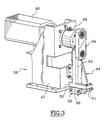
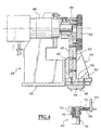
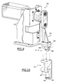
- the common mechanism 38 is illustrated in perspective in Figure 3 and in section in FIG. 4. In FIG. 4, a tool has also been illustrated. pusher 40 specific to the descent control to ensure the gripping the preform 10.
- the mechanism 38 comprises a frame 42 which is intended to be fixed on an oven rack.
- a square arm 44 is mounted so that it can slide in the gripping direction, that is to say in this case in the vertical direction.
- a sliding link formed on the one hand by a vertical rail 46 integral of a vertical upright 50 of the bracket 44, and on the other hand of a fixed carriage 48 integral with the chassis 42.
- the mechanism includes means for causing movement alternative of the square 44 in the axial direction of gripping.
- means for causing movement alternative of the square 44 in the axial direction of gripping.
- any other known means for imposing an alternating axial movement on bracket 44 can be used. So the movements of the square could be controlled by a cylinder.
- the shaped arm angle 44 has a horizontal bottom plate 52 on the face bottom of which is fixed a horizontal rail 54 forming part of a second slide link.
- a mobile carriage 56 is mounted on the rail horizontal 54 so that it can slide relative to the bracket 44 in a horizontal direction which is therefore perpendicular to the direction vertical gripping of the preform and which corresponds to the direction of displacement of the preform transport chain.
- the mobile carriage 56 is intended to carry one or the other of the two specific tools 40, 60 illustrated in more detail respectively in the figures 5 and 6.
- Each of these two tools 40, 60 has an upper plate 62 which is provided with indexing holes 64 intended to receive pawns indexing 58 which extend axially downwards from the carriage mobile 56.
- the plate 62 is fixed on the carriage 56 for example by two screws (not shown).
- Each of the two tools 40, 60 also includes a support plate 66 which extends in a vertical plane perpendicular to the direction of sliding of the mobile carriage 56 and which is intended to be fixed directly on the lower plate 52 of the bracket 44.
- the support plate 66 of each tool carries two parallel guides 68 which extend along the sliding direction of the movable carriage 56 and which are each received at sliding through a guide hole drilled in the plate 62.
- Guides 68 are used to support helical springs of compression 70 which are interposed between the plate 62 and the support plate 66 to separate them from each other.
- the free end of the guides 68 has a bulge against which the plate 62 abuts under the action of the springs 70.
- the plate 62 can slide in the horizontal direction relative to the bracket 44. However, under the action of the springs 70, it is returned to a rest position in which it abuts against the bulges 72 of the guides 68.
- FIGs 4 and 5 there is illustrated the pusher tool 40 intended for control the movement of a gripping device 16 downwards, simply by pressing on the upper face the control head 30 of this last.
- the push tool 40 has a tubular barrel 74 which extends axially downwards from the plate 62 and which is provided on its face internal thread with fine pitch to allow fixing and precise axial positioning of a cylindrical stud 76, the underside of which is intended to come to bear against the control head 30 to cause the descent.
- a lock nut 78 makes it possible to block the stud 76 on the barrel 74 to avoid any adjustment of its axial position.
- the fork tool 60 which is illustrated in FIG. 6 has two legs 80 in the form of parallel plates which extend vertically down from the plate 62.
- Each leg 80 has, at its lower end, an internal transverse rim 82 which extends in direction of the other leg.
- the transverse spacing and the height of the legs 80 are larger than the corresponding dimensions of the head control 30 so that the latter can flow between the two legs.
- the transverse spacing of the two flanges is greater than the diameter of the sheath 22 but less than that of the wheel toothed 32 so that when the head 30 is received between the two legs 80 and the fork tool 60 is moved up, the edges 82 cooperate with a lower face 33 of the head 30 for take it up.
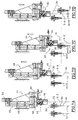
- FIGs of Figures 7A to 7D illustrate the operation of the control means according to the invention in the case of gripping the preform.
- the control head 30 of two successive links of the transport chain there is shown the control head 30 of two successive links of the transport chain.
- the gripping devices of these two links have respectively axes A n and A n + 1 .
- the bracket 44 is in a position initial high and we can see that the control head 30 from one of links approaches according to the movement of the transport chain, that is to say from left to right considering the figures.
- the underside of the pad 76 of the push tool 40 is then located higher than the head of command 30.
- the rod and crank system causes the beginning of the descent of the square arm 44.
- the push tool 40 is then in the rest position relative to the square, that is to say pushed in support to the left by the springs 70.
- step 7B we see that the link in the transport chain has moved until it comes partially in line with the push tool 40. This instant corresponds substantially to the moment at which the underside of the push-button 40 comes into contact with the control head 30.
- the pusher 40 exerts a push towards the control head bottom, allowing the gripping chuck 34 to penetrate inside of the neck 12 of the preform.
- the pusher 40 continues to move with the link in the transport chain according to the horizontal direction while square 44 cannot move according to this direction.
- the pusher 40 is then moved horizontally from its rest position by the head 30 by sliding of the mobile carriage 56 relative to the bracket 44, this in compressing the springs 70.
- this drive of the pusher 40 is done by simple adhesion of the underside of the pusher 40 to the head 30, without sliding of one relative to the other, this adhesion being the result of the axial gripping force necessary to allow the engagement of the mandrel 34 in the neck of the preform.
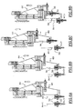
- FIGS 8A to 8D similarly illustrate the operation control means when the preform is released.
- FIG. 8A the mechanism is illustrated in the lower initial position, before the control head 30 of the first of the two links considered does not reach the fork tool 60.
- the edges 82 of the legs are then located below the underside 33 of the head 30 which is in its extreme low position. In this way, the head 30 can come to engage between the legs 80 due to the movement of the transport chain.
- FIG. 8B the contact position of the bracket 44 is illustrated. for which the flanges 82 come into contact with the head 30 during their upward movement. Again, contact occurs before the head 30 has not arrived exactly in line with the fork tool 60.
- the bracket 44 has reached its final high position, driving upwards the head 30 to its extreme high position.
- the head 30 drives the fork tool 60 in the horizontal direction by relative to the square 44, by compressing the springs 70.
- the electric motor 88 rotates at speed constant so that the rise and fall times of the tools 40, 60 are identical.
- the engine is controlled in such a way that one of the two movements of rise or descent occurs faster than the other for example in sight avoid any risk of tool interference with the next head when back movement.
- This possibility could also be used in view to obtain a predetermined speed of movement of the device gripping, regardless of the speed of movement of the chain conveying, which is linked for example to the rate of the blowing associated with the oven.
- Figures 9 and 10 illustrate two mechanisms according to lessons of the invention but in which the interface members by which the mechanism acts on the head 30 of the rod 20 are not slidably mounted on the arm 44, but consist of at least one roller mounted to rotate on the arm 44 around a horizontal axis for ability to roll on the head 30 of the rod 20.
- FIG. 9 it can be seen that under the lower plate 52 of the arm 44, a tool has been mounted to control the gripping device 16 from its high position to its low position.
- This tool consists of a simple roller 98 rotatably mounted on a yoke 96 about a horizontal axis Y-Y which is perpendicular to both the axial grip direction and the direction of movement of the conveyor chain.
- Clevis 98 is fixed rigidly under the bottom plate 52.
- the roller 98 comes to bear against the head of control 30. Once in contact, the roller 98 can push the rod 20 towards the bottom. At the same time, given the displacement of the link 18, the roller 98 rolls on head 30, without inducing any parasitic force on the link.
- FIG 10 there is shown a tool 89 intended to be fixed directly under the lower plate 52 of the arm 44 to ensure the ascent of the gripping device towards its high position.
- This tool 89 has a shape similar to that of the fork tool 60 described above, and it therefore comprises two parallel legs 90, each of them being provided at its lower end with an internal transverse rim 92.
- the tool 89 is fixed relative to the arm 44 but the edges 92 of the legs 90 are each provided with two rollers 94 which are rotatably mounted around their axes, which are perpendicular to both the axial direction of gripping and direction of movement of the conveyor chain. These rollers 94, which are flush above the upper face of the flanges 92, are intended to come into contact with the underside 33 of the head 30.
- the rollers 94 allow the head 30 to move by relative to arm 44 according to the direction of movement of the chain conveying without this relative displacement introducing any effort opposing the movement of the chain thanks to the fact that the contact between the rollers 94 and the head 30 is made with rolling and not with sliding.
- the mechanism according to the invention makes it possible to control the gripping device for each mechanism quickly, with a significant force and without introducing any parasitic force on the chain transport.
Landscapes
- Engineering & Computer Science (AREA)
- Manufacturing & Machinery (AREA)
- Mechanical Engineering (AREA)
- Physics & Mathematics (AREA)
- Thermal Sciences (AREA)
- Blow-Moulding Or Thermoforming Of Plastics Or The Like (AREA)
- Processing And Handling Of Plastics And Other Materials For Molding In General (AREA)
- Supplying Of Containers To The Packaging Station (AREA)
- Packages (AREA)
- Cold Air Circulating Systems And Constructional Details In Refrigerators (AREA)
Description
- le bras est commandé sur sa trajectoire selon un mouvement alternatif entre une position initiale et une position finale ; et, pour une position de contact du bras comprise entre ses positions initiale et finale, l'organe d'interface entre en contact avec le dispositif de préhension qui est dans l'une de ses positions extrêmes et le force vers l'autre de ses positions extrêmes, laquelle correspond à la position finale du bras ;
- l'organe d'interface est monté sur le bras de manière mobile selon une direction parallèle au mouvement des maillons de la chaíne ;
- l'organe d'interface est rappelé élastiquement vers une position de repos par rapport au bras, et, du fait du déplacement du chaínon correspondant entre le moment d'arrivée du bras en contact avec l'organe d'interface et le moment d'arrivée du bras à sa position finale, l'organe d'interface est écarté de sa position de repos par le dispositif de préhension au contact duquel il se trouve ;
- entre la position de contact et la position finale du bras, le dispositif de préhension coopère par adhérence avec l'organe d'interface pour l'écarter de sa position de repos par rapport au bras ;
- au cours du mouvement de retour du bras de sa position finale vers sa position initiale, l'organe d'interface est ramené vers sa position de repos par des moyens de rappel élastiques ;
- l'organe d'interface est monté à coulissement sur le bras selon la direction du mouvement des maillons de la chaíne ;
- l'organe d'interface est composé d'au moins un galet qui est monté à rotation sur le bras autour d'un axe perpendiculaire à la direction axiale de préhension et à la direction du mouvement des maillons de la chaíne ;
- entre le moment d'arrivée de l'organe d'interface en contact avec le dispositif de préhension et le moment d'arrivée du bras à sa position finale, le dispositif de préhension coopère par adhérence avec l'organe d'interface pour entraíner le galet en rotation autour de son axe ;
- le dispositif de préhension comporte une tige dont un tronçon central est guidé axialement dans le maillon correspondant et dont les deux extrémités opposées coopèrent respectivement avec l'ébauche et avec le mécanisme, le mécanisme exerce un effort de poussée sur la tige, et l'organe d'interface coopère en appui contre une surface de la tige qui est sensiblement plane et perpendiculaire à la direction axiale.
- le dispositif de préhension comporte une tige dont un tronçon central est guidé axialement dans le maillon correspondant et dont les deux extrémités opposées coopèrent respectivement avec l'ébauche et avec le mécanisme, le mécanisme exerce un effort de traction sur la tige, l'organe d'interface présente la forme d'un profilé en U présentant deux branches parallèles dont les extrémités sont rabattues vers l'intérieur pour délimiter une fente permettant le passage de la tige, la tige des dispositifs de préhension porte une tête de commande qui est destinée à circuler entre les deux branches du profilé et qui présente une largeur supérieure à la largeur de la fente de telle sorte que, lorsque l'organe d'interface est déplacé axialement par le bras, les extrémités rabattues du profilé coopèrent avec la tête pour commander le déplacement axial du dispositif de préhension ;
- le dispositif de préhension comporte une tige dont un tronçon central est guidé axialement dans le maillon correspondant et dont les deux extrémités opposées coopèrent respectivement avec l'ébauche et avec le mécanisme, le mécanisme exerce un effort de traction sur la tige ; le bras présente la forme d'un profilé en U présentant deux branches parallèles dont les extrémités sont rabattues vers l'intérieur pour délimiter une fente permettant le passage de la tige ; chacune des deux extrémités rabattues porte au moins galet ; la tige des dispositifs de préhension porte une tête de commande qui est destinée à circuler entre les deux branches du profilé et qui présente une largeur supérieure à la largeur de la fente de telle sorte que, lorsque le bras est déplacé axialement, les galets des extrémités rabattues du profilé coopèrent avec la tête pour commander le déplacement axial du dispositif de préhension ;
- le mouvement alternatif du bras est commandé par un système à bielle et à manivelle ; et
- les moyens de commande des déplacements des moyens de préhension comportent deux mécanismes dont l'un commande le déplacement des dispositifs de préhension de leur position extrême dégagée vers leur position extrême de préhension, et dont l'autre commande le déplacement inverse.
- les figures 1 et 2 sont des vues en coupe axiale qui illustrent le dispositif de préhension d'un maillon de la chaíne de transport, ce dispositif étant illustré respectivement dans une position haute dégagée et dans une position basse de préhension d'une préforme ;
- la figure 3 est une vue en perspective illustrant un mode de réalisation d'un mécanisme de commande des déplacements du dispositif de préhension ;
- la figures 4 est une vue en coupe des moyens de commande illustrés à la figure 3, et sur laquelle on a illustré de plus l'outil adaptable sur ce mécanisme pour commander le déplacement du dispositif de préhension de sa position haute vers sa position basse, cet outil étant plus particulièrement illustré en perspective à la figure 5 ;
- la figure 6 illustre, en perspective, un outil adaptable sur le mécanisme de commande pour ramener le dispositif de préhension de sa position basse vers sa position haute :
- les figures 7A à 7D illustrent, de manière schématique en coupe axiale, une opération permettant la préhension de la préforme ;
- les figures 8A à 8D illustrent de la même manière une opération permettant la libération de la préforme ; et
- les figures 9 et 10 sont des vues similaires à celles de la figure 3 illustrant des variantes de réalisation de l'invention.
Claims (14)
- Four de conditionnement thermique pour une installation de fabrication par soufflage de récipients en matériau thermoplastique, du type comportant une chaíne de maillons de transport comportant des dispositifs de préhension (16) dont chacun est destiné à porter une ébauche (10) du récipient en vue de la faire circuler le long d'un parcours à l'intérieur du four, du type dans lequel la chaíne est animée d'un mouvement continu le long de son parcours, du type dans lequel chaque dispositif de préhension (16) est mobile axialement par rapport au maillon (18) qui le porte pour, lorsqu'il est amené d'une position extrême dégagée à une position extrême de préhension, s'engager axialement sur le col (12) de l'ébauche (10), et du type dans lequel il est prévu des moyens de commande des déplacements des dispositifs de préhension entre leurs positions dégagée et de préhension,
caractérisé en ce que les moyens de commande des déplacements des dispositifs de préhension comportent au moins un mécanisme pourvu d'un bras (44) qui est mobile selon une trajectoire sensiblement parallèle à la direction axiale (An) de préhension et qui porte un organe d'interface (40, 60, 94, 98) destiné à venir au contact du dispositif de préhension (16), et en ce que l'organe d'interface (40, 60, 94, 98) est monté mobile sur le bras (44) de manière à permettre un contact sans glissement avec le dispositif de préhension (16) tout en étant immobilisé par rapport au bras (44) selon la direction axiale de préhension. - Four selon la revendication 1, caractérisé en ce que le bras (44) est commandé sur sa trajectoire selon un mouvement alternatif entre une position initiale et une position finale, et en ce que, pour une position de contact du bras comprise entre ses positions initiale et finale, l'organe d'interface (40, 60, 94, 98) entre en contact avec le dispositif de préhension (30, 16) qui est dans l'une de ses positions extrêmes et le force vers l'autre de ses positions extrêmes, laquelle correspond à la position finale du bras (44).
- Four selon la revendication 1 ou 2, caractérisé en ce que l'organe d'interface (40, 60) est monté sur le bras (44) de manière mobile selon une direction parallèle au mouvement des maillons de la chaíne.
- Four selon la revendication 3, caractérisé en ce que l'organe d'interface (40, 60) est rappelé élastiquement vers une position de repos par rapport au bras (44), et en ce que, du fait du déplacement du chaínon (18) correspondant entre le moment d'arrivée du bras en contact avec l'organe d'interface et le moment d'arrivée du bras à sa position finale, l'organe d'interface (40, 60) est écarté de sa position de repos par le dispositif de préhension (30, 16) au contact duquel il se trouve.
- Four selon la revendication 4, caractérisé en ce que, entre la position de contact et la position finale du bras (44), le dispositif de préhension (30, 16) coopère par adhérence avec l'organe d'interface (40, 60) pour l'écarter de sa position de repos par rapport au bras (44).
- Four selon l'une des revendications 4 ou 5, caractérisé en ce que, au cours du mouvement de retour du bras (44) de sa position finale vers sa position initiale, l'organe d'interface (40, 60) est ramené vers sa position de repos par des moyens de rappel élastiques (70).
- Four selon l'une quelconque des revendications 3 à 6, caractérisé en ce que l'organe d'interface (40, 60) est monté à coulissement sur le bras selon la direction du mouvement des maillons de la chaíne.
- Four selon l'une des revendications 1 ou 2, caractérisé en ce que l'organe d'interface est composé d'au moins un galet (94, 98) qui est monté à rotation sur le bras autour d'un axe (Y-Y) perpendiculaire à la direction axiale de préhension et à la direction du mouvement des maillons (18) de la chaíne.
- Four selon la revendication 8, caractérisé en ce que entre le moment d'arrivée de l'organe d'interface (94, 98) en contact avec le dispositif de préhension et le moment d'arrivée du bras (44) à sa position finale, le dispositif de préhension (30, 16) coopère par adhérence avec l'organe d'interface (40, 60) pour entraíner le galet en rotation autour de son axe.
- Four selon l'une quelconque des revendications précédentes, caractérisé en ce que le dispositif de préhension (16) comporte une tige (20) dont un tronçon central est guidé axialement dans le maillon (18) correspondant et dont les deux extrémités opposées (34, 30) coopèrent respectivement avec l'ébauche (10) et avec le mécanisme, en ce que le mécanisme exerce un effort de poussée sur la tige (20), et en ce que l'organe d'interface (40, 98) coopère en appui contre une surface (30) de la tige (20) qui est sensiblement plane et perpendiculaire à la direction axiale.
- Four selon l'une quelconque des revendications 3 à 7, caractérisé en ce que le dispositif de préhension comporte une tige (20) dont un tronçon central est guidé axialement dans le maillon (18) correspondant et dont les deux extrémités opposées (34, 30) coopèrent respectivement avec l'ébauche (10) et avec le mécanisme, en ce que le mécanisme exerce un effort de traction sur la tige (20), en ce que l'organe d'interface (60) présente la forme d'un profilé en U présentant deux branches parallèles (80) dont les extrémités (82) sont rabattues vers l'intérieur pour délimiter une fente permettant le passage de la tige (20), en ce que la tige (20) des dispositifs de préhension porte une tête de commande (30) qui est destinée à circuler entre les deux branches (80) du profilé et qui présente une largeur supérieure à la largeur de la fente de telle sorte que, lorsque l'organe d'interface (60) est déplacé axialement par le bras (44), les extrémités rabattues (82) du profilé coopèrent avec la tête (30) pour commander le déplacement axial du dispositif de préhension (16).
- Four selon l'une des revendications 8 ou 9, caractérisé en ce que le dispositif de préhension comporte une tige (20) dont un tronçon central est guidé axialement dans le maillon (18) correspondant et dont les deux extrémités opposées (34, 30) coopèrent respectivement avec l'ébauche (10) et avec le mécanisme, en ce que le mécanisme exerce un effort de traction sur la tige (20), en ce que le bras (44) présente la forme d'un profilé en U présentant deux branches parallèles (90) dont les extrémités (92) sont rabattues vers l'intérieur pour délimiter une fente permettant le passage de la tige (20), en ce que chacune des deux extrémités rabattues (92) porte au moins galet (94), en ce que la tige (20) des dispositifs de préhension porte une tête de commande (30) qui est destinée à circuler entre les deux branches (90) du profilé et qui présente une largeur supérieure à la largeur de la fente de telle sorte que, lorsque le bras (44) est déplacé axialement, les galets (94) des extrémités rabattues (92) du profilé coopèrent avec la tête (30) pour commander le déplacement axial du dispositif de préhension (16).
- Four selon l'une quelconque des revendications précédentes, caractérisé en ce que le mouvement alternatif du bras (44) est commandé par un système à bielle (84) et à manivelle (86).
- Four selon l'une quelconque des revendications précédentes, caractérisé en ce que les moyens de commande des déplacements des moyens de préhension comportent deux mécanismes dont l'un commande le déplacement des dispositifs de préhension (16) de leur position extrême dégagée vers leur position extrême de préhension, et dont l'autre commande le déplacement inverse.
Applications Claiming Priority (3)
| Application Number | Priority Date | Filing Date | Title |
|---|---|---|---|
| FR9905336A FR2792569B1 (fr) | 1999-04-26 | 1999-04-26 | Four de conditionnement thermique pour une installation de fabrication par soufflage de recipients en materiau thermoplastique |
| FR9905336 | 1999-04-26 | ||
| PCT/FR2000/000836 WO2000064658A1 (fr) | 1999-04-26 | 2000-04-04 | Four de conditionnement thermique pour une installation de fabrication par soufflage de recipients en materiau thermoplastique |
Publications (2)
| Publication Number | Publication Date |
|---|---|
| EP1180069A1 EP1180069A1 (fr) | 2002-02-20 |
| EP1180069B1 true EP1180069B1 (fr) | 2003-07-09 |
Family
ID=9544929
Family Applications (1)
| Application Number | Title | Priority Date | Filing Date |
|---|---|---|---|
| EP00915280A Expired - Lifetime EP1180069B1 (fr) | 1999-04-26 | 2000-04-04 | Four de conditionnement thermique pour une installation de fabrication par soufflage de recipients en materiau thermoplastique |
Country Status (15)
| Country | Link |
|---|---|
| US (1) | US6811389B1 (fr) |
| EP (1) | EP1180069B1 (fr) |
| JP (1) | JP3737032B2 (fr) |
| KR (1) | KR100430833B1 (fr) |
| CN (1) | CN1121311C (fr) |
| AT (1) | ATE244631T1 (fr) |
| AU (1) | AU772777B2 (fr) |
| BR (1) | BR0010023B1 (fr) |
| CA (1) | CA2371256C (fr) |
| DE (1) | DE60003813T2 (fr) |
| ES (1) | ES2203440T3 (fr) |
| FR (1) | FR2792569B1 (fr) |
| MX (1) | MXPA01010741A (fr) |
| PT (1) | PT1180069E (fr) |
| WO (1) | WO2000064658A1 (fr) |
Families Citing this family (13)
| Publication number | Priority date | Publication date | Assignee | Title |
|---|---|---|---|---|
| US7264464B2 (en) * | 2003-06-09 | 2007-09-04 | Husky Injection Molding Systems Ltd. | Cooling tube with a low friction coating |
| CN100363170C (zh) * | 2004-06-09 | 2008-01-23 | 蔡佳祎 | 全自动塑料瓶管加热器 |
| DE102005062440B4 (de) * | 2005-12-27 | 2011-02-24 | Lts Lohmann Therapie-Systeme Ag | Proteinbasiertes Trägersystem zur Resistenzüberwindung von Tumorzellen |
| EP1985286A1 (fr) * | 2007-04-24 | 2008-10-29 | Biocompatibles UK Limited | Microsphères pour le traitement de tumeurs cérébrales |
| IT1398130B1 (it) * | 2009-06-30 | 2013-02-14 | Sacmi | Apparato di riscaldamento di preforme in materiale termoplastico |
| IT1395015B1 (it) * | 2009-06-30 | 2012-09-05 | Sacmi | Apparato di riscaldamento di preforme in materiale termoplastico. |
| US8287270B2 (en) * | 2009-09-30 | 2012-10-16 | Printpack Illinois Inc. | Methods and systems for thermoforming with billets |
| FR2957904B1 (fr) * | 2010-03-29 | 2012-04-20 | Sidel Participations | Dispositif de prehension pour preforme de soufflage de recipient |
| FR2986453B1 (fr) * | 2012-02-08 | 2014-03-21 | Sidel Participations | Organe de prehension de recipients comportant un nez demontable equipe d'un mandrin et d'un plateau d'ejection |
| WO2015181738A1 (fr) * | 2014-05-28 | 2015-12-03 | S.I.P.A. Societa' Industrializzazione Progettazione E Automazione S.P.A. | Appareil pour le transport de recipients en matiere plastique |
| DE102016112131A1 (de) * | 2016-07-01 | 2018-01-04 | Khs Corpoplast Gmbh | Dornenkette mit Magnethalterung |
| FR3151784A1 (fr) * | 2023-08-01 | 2025-02-07 | Sidel Participations | Dispositif d’éjection de préformes pour une installation de fabrication par soufflage de récipients en matériau thermoplastique à partir de préformes |
| CN119706335B (zh) * | 2025-01-13 | 2025-10-17 | 湖南亚辉龙生物科技有限公司 | 旋转夹爪及转移装置 |
Family Cites Families (7)
| Publication number | Priority date | Publication date | Assignee | Title |
|---|---|---|---|---|
| US4086999A (en) * | 1976-03-18 | 1978-05-02 | Cincinnati Milacron Inc. | Conveyor combined with coupling for handling workpiece |
| DE2706567C2 (de) * | 1976-03-18 | 1985-11-14 | Cincinnati Milacron Inc. (eine Ges. n.d. Gesetzen d. Staates Delaware), Cincinnati, Ohio | Greifvorrichtung für hohle Werkstücke |
| DE3110883C2 (de) * | 1981-03-20 | 1983-12-22 | Conto control Braschos KG, 5900 Siegen | Vorrichtung zum Aussortieren von fehlerhaften Verpackungseinheiten |
| US4572355A (en) * | 1984-10-03 | 1986-02-25 | Sewell Plastics, Inc. | Coupling assembly |
| US4763778A (en) * | 1986-06-23 | 1988-08-16 | Fedders Machine And Tool Co., Inc. | Easily changeable gripping head for blow-molding pallet assembly |
| DE3916423C1 (en) * | 1989-05-19 | 1990-11-29 | Centro Kontrollsysteme Gmbh, 5900 Siegen, De | Automatic bottle sorting installation - incorporates lateral pusher transferring individual bottles onto second conveyor track |
| FR2691401B1 (fr) * | 1992-05-20 | 1994-08-05 | Sidel Sa | Unite pour le traitement thermique de recipients en pet lors de la fabrication de ceux-ci. |
-
1999
- 1999-04-26 FR FR9905336A patent/FR2792569B1/fr not_active Expired - Fee Related
-
2000
- 2000-04-04 AT AT00915280T patent/ATE244631T1/de not_active IP Right Cessation
- 2000-04-04 DE DE60003813T patent/DE60003813T2/de not_active Expired - Lifetime
- 2000-04-04 WO PCT/FR2000/000836 patent/WO2000064658A1/fr not_active Ceased
- 2000-04-04 KR KR10-2001-7013642A patent/KR100430833B1/ko not_active Expired - Fee Related
- 2000-04-04 AU AU36650/00A patent/AU772777B2/en not_active Ceased
- 2000-04-04 ES ES00915280T patent/ES2203440T3/es not_active Expired - Lifetime
- 2000-04-04 US US09/959,378 patent/US6811389B1/en not_active Expired - Lifetime
- 2000-04-04 CN CN00806804A patent/CN1121311C/zh not_active Expired - Fee Related
- 2000-04-04 EP EP00915280A patent/EP1180069B1/fr not_active Expired - Lifetime
- 2000-04-04 CA CA002371256A patent/CA2371256C/fr not_active Expired - Fee Related
- 2000-04-04 BR BRPI0010023-4A patent/BR0010023B1/pt not_active IP Right Cessation
- 2000-04-04 MX MXPA01010741A patent/MXPA01010741A/es active IP Right Grant
- 2000-04-04 PT PT00915280T patent/PT1180069E/pt unknown
- 2000-04-04 JP JP2000613634A patent/JP3737032B2/ja not_active Expired - Fee Related
Also Published As
| Publication number | Publication date |
|---|---|
| DE60003813D1 (de) | 2003-08-14 |
| CA2371256A1 (fr) | 2000-11-02 |
| AU772777B2 (en) | 2004-05-06 |
| CN1349455A (zh) | 2002-05-15 |
| JP3737032B2 (ja) | 2006-01-18 |
| ES2203440T3 (es) | 2004-04-16 |
| BR0010023A (pt) | 2002-01-15 |
| KR20020016774A (ko) | 2002-03-06 |
| FR2792569B1 (fr) | 2001-08-03 |
| WO2000064658A1 (fr) | 2000-11-02 |
| US6811389B1 (en) | 2004-11-02 |
| PT1180069E (pt) | 2003-11-28 |
| CN1121311C (zh) | 2003-09-17 |
| CA2371256C (fr) | 2007-06-19 |
| DE60003813T2 (de) | 2004-06-03 |
| AU3665000A (en) | 2000-11-10 |
| JP2002542083A (ja) | 2002-12-10 |
| EP1180069A1 (fr) | 2002-02-20 |
| FR2792569A1 (fr) | 2000-10-27 |
| MXPA01010741A (es) | 2002-06-04 |
| ATE244631T1 (de) | 2003-07-15 |
| KR100430833B1 (ko) | 2004-05-10 |
| BR0010023B1 (pt) | 2009-08-11 |
Similar Documents
| Publication | Publication Date | Title |
|---|---|---|
| CA2371256C (fr) | Four de conditionnement thermique pour une installation de fabrication par soufflage de recipients en materiau thermoplastique | |
| CA2214099C (fr) | Installation de fabrication de recipients par soufflage de preformes en matiere plastique | |
| EP2686259A1 (fr) | Dispositif de transfert comportant une pince de prehension | |
| EP2139666B1 (fr) | Dispositif de transfert et installation de type lineaire pour la fabrication de recipients | |
| CA2164945C (fr) | Installation de fabrication de recipients par soufflage de preformes en matiere plastique | |
| EP2964445B1 (fr) | Dispositif de transport d'un corps creux comportant des moyens de préhension perfectionnés | |
| EP2626177B2 (fr) | Organe de préhension de récipients comportant un nez démontable équipé d'un mandrin et d'un plateau d'éjection | |
| FR2679818A1 (fr) | Procede et dispositif pour la decoupe de plaques de verre plat. | |
| WO2006084990A1 (fr) | Dispositif rotatif de transfert de recipients | |
| EP3909743A1 (fr) | Installation de transport de preformes equipee d'un dispositif d'indexage angulaire de tournettes | |
| EP0842036B1 (fr) | Dispositif de moulage de recipients en materiau thermoplastique et installation de fabrication de recipients en faisant application | |
| EP1216197A1 (fr) | Systeme de convoyage d'ebauches dans une installation de soufflage de recipients | |
| EP3427917B1 (fr) | Dispositif à mandrin pour convoyage de corps creux et installation de fabrication de recipients | |
| WO2011121208A1 (fr) | Dispositif de prehension pour preforme de soufflage de recipient | |
| EP0069011A1 (fr) | Dispositif de pose et centrage de gaine thermoplastique autour d'objets au moyen d'un ensemble vertical à mandrin flottant | |
| FR2543880A1 (fr) | Dispositif d'actionnement d'un mandrin de machine de moulage par soufflage de recipients en polymere thermoplastique | |
| FR2879179A1 (fr) | Dispositif de transfert d'articles au moyen d'un groupe de modules a ecartement variable | |
| EP3546194B1 (fr) | Dispositif de convoyage muni d'un systeme de securite | |
| EP0008481A1 (fr) | Dispositif pour l'étirage à chaud de préformes en matière thermoplastique lors de leur moulage par soufflage | |
| WO2013171141A1 (fr) | Installation de fabrication de recipients comportant des moyens de transmission de mouvement a plusieurs vitesses entre un convoyeur et une station de formage | |
| EP0220967A1 (fr) | Convoyeur de récipients | |
| WO2024068822A1 (fr) | Procede de transfert de preforme sur un convoyeur | |
| EP0337906A1 (fr) | Procédé de positionnement dans une orientation déterminée d'articles allongés hétérogènes et mécanismes destinés à sa mise en oeuvre | |
| FR2598400A1 (fr) | Procede et installation pour former des jupes thermoretractables sur des recipients de formes non regulieres | |
| FR2612487A1 (fr) | Procede d'encaissage en continu et suivant des couches superposees, d'objets tels que par exemple des recipients, et machine comportant application de ce procede |
Legal Events
| Date | Code | Title | Description |
|---|---|---|---|
| PUAI | Public reference made under article 153(3) epc to a published international application that has entered the european phase |
Free format text: ORIGINAL CODE: 0009012 |
|
| 17P | Request for examination filed |
Effective date: 20011126 |
|
| AK | Designated contracting states |
Kind code of ref document: A1 Designated state(s): AT BE CH CY DE DK ES FI FR GB GR IE IT LI LU MC NL PT SE |
|
| GRAH | Despatch of communication of intention to grant a patent |
Free format text: ORIGINAL CODE: EPIDOS IGRA |
|
| RAP1 | Party data changed (applicant data changed or rights of an application transferred) |
Owner name: SIDEL |
|
| GRAH | Despatch of communication of intention to grant a patent |
Free format text: ORIGINAL CODE: EPIDOS IGRA |
|
| GRAA | (expected) grant |
Free format text: ORIGINAL CODE: 0009210 |
|
| AK | Designated contracting states |
Designated state(s): AT BE CH CY DE DK ES FI FR GB GR IE IT LI LU MC NL PT SE |
|
| PG25 | Lapsed in a contracting state [announced via postgrant information from national office to epo] |
Ref country code: FI Free format text: LAPSE BECAUSE OF FAILURE TO SUBMIT A TRANSLATION OF THE DESCRIPTION OR TO PAY THE FEE WITHIN THE PRESCRIBED TIME-LIMIT Effective date: 20030709 Ref country code: CY Free format text: LAPSE BECAUSE OF FAILURE TO SUBMIT A TRANSLATION OF THE DESCRIPTION OR TO PAY THE FEE WITHIN THE PRESCRIBED TIME-LIMIT Effective date: 20030709 Ref country code: IE Free format text: LAPSE BECAUSE OF FAILURE TO SUBMIT A TRANSLATION OF THE DESCRIPTION OR TO PAY THE FEE WITHIN THE PRESCRIBED TIME-LIMIT Effective date: 20030709 Ref country code: AT Free format text: LAPSE BECAUSE OF FAILURE TO SUBMIT A TRANSLATION OF THE DESCRIPTION OR TO PAY THE FEE WITHIN THE PRESCRIBED TIME-LIMIT Effective date: 20030709 |
|
| REG | Reference to a national code |
Ref country code: GB Ref legal event code: FG4D Free format text: NOT ENGLISH |
|
| REG | Reference to a national code |
Ref country code: CH Ref legal event code: EP |
|
| REF | Corresponds to: |
Ref document number: 60003813 Country of ref document: DE Date of ref document: 20030814 Kind code of ref document: P |
|
| REG | Reference to a national code |
Ref country code: IE Ref legal event code: FG4D Free format text: FRENCH |
|
| PG25 | Lapsed in a contracting state [announced via postgrant information from national office to epo] |
Ref country code: GR Free format text: LAPSE BECAUSE OF FAILURE TO SUBMIT A TRANSLATION OF THE DESCRIPTION OR TO PAY THE FEE WITHIN THE PRESCRIBED TIME-LIMIT Effective date: 20031009 Ref country code: DK Free format text: LAPSE BECAUSE OF FAILURE TO SUBMIT A TRANSLATION OF THE DESCRIPTION OR TO PAY THE FEE WITHIN THE PRESCRIBED TIME-LIMIT Effective date: 20031009 |
|
| REG | Reference to a national code |
Ref country code: SE Ref legal event code: TRGR |
|
| REG | Reference to a national code |
Ref country code: CH Ref legal event code: NV Representative=s name: KELLER & PARTNER PATENTANWAELTE AG |
|
| GBT | Gb: translation of ep patent filed (gb section 77(6)(a)/1977) |
Effective date: 20031025 |
|
| REG | Reference to a national code |
Ref country code: IE Ref legal event code: FD4D |
|
| PG25 | Lapsed in a contracting state [announced via postgrant information from national office to epo] |
Ref country code: LU Free format text: LAPSE BECAUSE OF NON-PAYMENT OF DUE FEES Effective date: 20040404 |
|
| REG | Reference to a national code |
Ref country code: ES Ref legal event code: FG2A Ref document number: 2203440 Country of ref document: ES Kind code of ref document: T3 |
|
| PG25 | Lapsed in a contracting state [announced via postgrant information from national office to epo] |
Ref country code: MC Free format text: LAPSE BECAUSE OF NON-PAYMENT OF DUE FEES Effective date: 20040430 |
|
| PLBE | No opposition filed within time limit |
Free format text: ORIGINAL CODE: 0009261 |
|
| STAA | Information on the status of an ep patent application or granted ep patent |
Free format text: STATUS: NO OPPOSITION FILED WITHIN TIME LIMIT |
|
| 26N | No opposition filed |
Effective date: 20040414 |
|
| PGFP | Annual fee paid to national office [announced via postgrant information from national office to epo] |
Ref country code: BE Payment date: 20060323 Year of fee payment: 7 |
|
| PGFP | Annual fee paid to national office [announced via postgrant information from national office to epo] |
Ref country code: CH Payment date: 20060329 Year of fee payment: 7 |
|
| REG | Reference to a national code |
Ref country code: CH Ref legal event code: PL |
|
| BERE | Be: lapsed |
Owner name: *SIDEL Effective date: 20070430 |
|
| PG25 | Lapsed in a contracting state [announced via postgrant information from national office to epo] |
Ref country code: CH Free format text: LAPSE BECAUSE OF NON-PAYMENT OF DUE FEES Effective date: 20070430 Ref country code: LI Free format text: LAPSE BECAUSE OF NON-PAYMENT OF DUE FEES Effective date: 20070430 |
|
| PG25 | Lapsed in a contracting state [announced via postgrant information from national office to epo] |
Ref country code: BE Free format text: LAPSE BECAUSE OF NON-PAYMENT OF DUE FEES Effective date: 20070430 |
|
| PGFP | Annual fee paid to national office [announced via postgrant information from national office to epo] |
Ref country code: SE Payment date: 20100325 Year of fee payment: 11 |
|
| REG | Reference to a national code |
Ref country code: SE Ref legal event code: EUG |
|
| PG25 | Lapsed in a contracting state [announced via postgrant information from national office to epo] |
Ref country code: SE Free format text: LAPSE BECAUSE OF NON-PAYMENT OF DUE FEES Effective date: 20110405 |
|
| PGFP | Annual fee paid to national office [announced via postgrant information from national office to epo] |
Ref country code: PT Payment date: 20150401 Year of fee payment: 16 |
|
| REG | Reference to a national code |
Ref country code: FR Ref legal event code: PLFP Year of fee payment: 17 |
|
| PGFP | Annual fee paid to national office [announced via postgrant information from national office to epo] |
Ref country code: NL Payment date: 20160321 Year of fee payment: 17 |
|
| PGFP | Annual fee paid to national office [announced via postgrant information from national office to epo] |
Ref country code: GB Payment date: 20160324 Year of fee payment: 17 Ref country code: FR Payment date: 20160323 Year of fee payment: 17 |
|
| PGFP | Annual fee paid to national office [announced via postgrant information from national office to epo] |
Ref country code: DE Payment date: 20160321 Year of fee payment: 17 Ref country code: ES Payment date: 20160407 Year of fee payment: 17 |
|
| PGFP | Annual fee paid to national office [announced via postgrant information from national office to epo] |
Ref country code: IT Payment date: 20160324 Year of fee payment: 17 |
|
| PG25 | Lapsed in a contracting state [announced via postgrant information from national office to epo] |
Ref country code: PT Free format text: LAPSE BECAUSE OF NON-PAYMENT OF DUE FEES Effective date: 20161004 |
|
| REG | Reference to a national code |
Ref country code: DE Ref legal event code: R119 Ref document number: 60003813 Country of ref document: DE |
|
| REG | Reference to a national code |
Ref country code: NL Ref legal event code: MM Effective date: 20170501 |
|
| GBPC | Gb: european patent ceased through non-payment of renewal fee |
Effective date: 20170404 |
|
| REG | Reference to a national code |
Ref country code: FR Ref legal event code: ST Effective date: 20171229 |
|
| PG25 | Lapsed in a contracting state [announced via postgrant information from national office to epo] |
Ref country code: NL Free format text: LAPSE BECAUSE OF NON-PAYMENT OF DUE FEES Effective date: 20170501 Ref country code: FR Free format text: LAPSE BECAUSE OF NON-PAYMENT OF DUE FEES Effective date: 20170502 Ref country code: DE Free format text: LAPSE BECAUSE OF NON-PAYMENT OF DUE FEES Effective date: 20171103 |
|
| PG25 | Lapsed in a contracting state [announced via postgrant information from national office to epo] |
Ref country code: GB Free format text: LAPSE BECAUSE OF NON-PAYMENT OF DUE FEES Effective date: 20170404 |
|
| PG25 | Lapsed in a contracting state [announced via postgrant information from national office to epo] |
Ref country code: IT Free format text: LAPSE BECAUSE OF NON-PAYMENT OF DUE FEES Effective date: 20170404 |
|
| REG | Reference to a national code |
Ref country code: ES Ref legal event code: FD2A Effective date: 20180629 |
|
| PG25 | Lapsed in a contracting state [announced via postgrant information from national office to epo] |
Ref country code: ES Free format text: LAPSE BECAUSE OF NON-PAYMENT OF DUE FEES Effective date: 20170405 |