EP1179883A2 - Polarizing device for a permanent magnet rotor - Google Patents
Polarizing device for a permanent magnet rotor Download PDFInfo
- Publication number
- EP1179883A2 EP1179883A2 EP01118700A EP01118700A EP1179883A2 EP 1179883 A2 EP1179883 A2 EP 1179883A2 EP 01118700 A EP01118700 A EP 01118700A EP 01118700 A EP01118700 A EP 01118700A EP 1179883 A2 EP1179883 A2 EP 1179883A2
- Authority
- EP
- European Patent Office
- Prior art keywords
- coil
- permanent magnet
- polarizing
- iron core
- coils
- Prior art date
- Legal status (The legal status is an assumption and is not a legal conclusion. Google has not performed a legal analysis and makes no representation as to the accuracy of the status listed.)
- Granted
Links
Images


Classifications
-
- H—ELECTRICITY
- H02—GENERATION; CONVERSION OR DISTRIBUTION OF ELECTRIC POWER
- H02K—DYNAMO-ELECTRIC MACHINES
- H02K15/00—Processes or apparatus specially adapted for manufacturing, assembling, maintaining or repairing of dynamo-electric machines
- H02K15/02—Processes or apparatus specially adapted for manufacturing, assembling, maintaining or repairing of dynamo-electric machines of stator or rotor bodies
- H02K15/03—Processes or apparatus specially adapted for manufacturing, assembling, maintaining or repairing of dynamo-electric machines of stator or rotor bodies having permanent magnets
-
- H—ELECTRICITY
- H02—GENERATION; CONVERSION OR DISTRIBUTION OF ELECTRIC POWER
- H02K—DYNAMO-ELECTRIC MACHINES
- H02K15/00—Processes or apparatus specially adapted for manufacturing, assembling, maintaining or repairing of dynamo-electric machines
-
- H—ELECTRICITY
- H01—ELECTRIC ELEMENTS
- H01F—MAGNETS; INDUCTANCES; TRANSFORMERS; SELECTION OF MATERIALS FOR THEIR MAGNETIC PROPERTIES
- H01F13/00—Apparatus or processes for magnetising or demagnetising
- H01F13/003—Methods and devices for magnetising permanent magnets
Definitions
- This invention relates to a polarizing device in which unmagnetized permanent magnets arranged on the peripheral surface of a rotor are magnetized to form magnetic poles in turn.
- a conventional polarizing device of a permanent magnet rotor of this kind for example, as shown in Japanese Patent Application Laid-Open No.9-163692 which is not shown in the figure, a device is disclosed, where the polarizing iron core is arranged around the rotor and in the meantime, a coil is wound at a position respectively corresponding to each unmagnetized permanent magnet of the rotor of this polarizing iron core, and by letting the current flow in each of these coils, respectively so that the directions of the flow of the adjacent fellow coils may be different, each unmagnetized permanent magnet is magnetized and polarized to a magnetic pole of N-pole or S-pole alternately.
- the device becomes large-sized since the polarizing iron core is arranged around the rotor, and therefore, for example, in Japanese Patent Application Laid-Open No.10-336976, a method is disclosed, where at a position corresponding to either of the respective unmagnetized permanent magnets of the rotor, a polarizing iron core of one pole on which a coil is wound is arranged and polarized, and after that, by relatively moving the rotor or the polarizing iron core by a pitch of the unmagnetized permanent magnet while switching in turn the direction of the current flowing in the coil, each unmagnetized permanent magnet is magnetized one by one in turn, and is alternately polarized to N-pole or S-pole, and consequently, miniaturization is achieved.
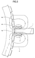
- the conventional polarizing device of a permanent magnet rotor achieves the miniaturization as a device, as described above, in such a way that the polarizing iron core for one pole on which a coil is wound is magnetized while switching the direction of the current flowing in the coil in turn and corresponding to each unmagnetized permanent magnet and is polarized to N-pole or S-pole, and therefore, as shown in Fig.
- the magnetic flux 3 passes through the respective unmagnetized permanent magnets 4b, 4c near the unmagnetized permanent magnet 4a in the opposite direction of the magnetizing direction and the polarization is performed in the opposite direction of the direction in which the magnetizing should be performed, and therefore, in the case where the polarizing is normally performed in the desired direction at a position corresponding to the polarizing iron core 1, the polarizing in the reverse direction must be demagnetized and therefore, it is necessary to change the current flowing in the coil 2 each time, and there has been such a problem that the control of the current becomes difficult.
- the demagnetizing is difficult and the re-magnetizing needs a considerably strong magnetic field when compared with the unmagnetized one, and there has been such a problem that the current supplying unit becomes large-sized.
- This invention is made to solve the described problems, and it is an object to provide a polarizing device of a permanent magnet rotor in which the effect of the opposing magnetic field is eliminated and the control of the current is easy.
- a polarizing device for a permanent magnet rotor comprising: a polarizing iron core arranged facing to a specified number of permanent magnets among a plurality of unmagnetized permanent magnets arranged at specified intervals in the circumferential direction on the peripheral surface of a rotor; a first coil wound at a position facing to a desired permanent magnet of the polarizing iron core; a pair of second coils each of which is arranged having a specified interval on the basis of the first coil in the circumferential direction on the polarizing iron core and whose direction of the flowing current is different from that of the first coil; and a power source for supplying the current to the first and second coils, wherein either of the permanent magnet and first coil is relatively moved and each permanent magnet is magnetized to form a magnetic pole in turn by the current fed from the power source.
- each second coil is arranged having an interval corresponding to at least three permanent magnets with the first coil.
- the polarizing device for a permanent magnet rotor according to the first aspect, wherein the second coils are wound in the direction different from that of the first coil.
- the polarizing device for a permanent magnet rotor according to the third aspect, wherein the second coils are wound by a number of windings of half the number of windings of the first coil or less.
- the polarizing device for a permanent magnet rotor according to the first aspect, wherein a notch part for expanding the clearance with the permanent magnet is formed near both sides of the first coil of the polarizing iron core.
- the polarizing device for a permanent magnet rotor according to the first aspect, wherein the permanent magnet is relatively moved by rotating the rotor.
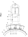
- Fig.1 is a schematic diagram showing the structure of a polarizing device of a permanent magnet rotor in embodiment 1 of this invention
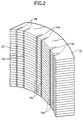
- Fig.2 is a perspective illustration showing the structure of a polarizing iron core in Fig. 1
- Fig. 3 is a figure showing the state of distribution of magnetic flux generated by the polarizing device of a permanent magnet rotor in Fig.1.
- reference numeral 11 denotes a plurality of unmagnetized permanent magnets arranged in the circumferential direction on the peripheral surface of a rotor 12 at specified intervals
- reference numeral 13 denotes a polarizing iron core arranged facing to a specified number of permanent magnets 11, and as shown in Fig.2, it is formed by laminating a specified number of plate magnetic materials 14 in which a pair of notches 14a having a specified width and a specified depth are formed at three positions at specified intervals (in the figure, intervals corresponding to three permanent magnets 11), and a coil inserting groove 13a for winding each coil which is described later is formed by the notch 14a of each plate magnetic material 14.
- Reference numeral 15 denotes a first coil to be wound and inserted into a pair of coil inserting grooves 13a at the central part of the polarizing iron core 13
- reference numeral 16 denotes a pair of second coils each of which is wound and inserted into each of the pair of grooves 13a at both end parts of the polarizing iron core 13, and each is wound in the direction different from that of the first coil 15 and by a number of windings of half the number of windings of the first coil 15 or less.
- Reference numeral 17 denotes a power source
- reference numeral 18 denotes a charge circuit for charging a condenser 19 from this power source 17, and it makes up a current supplying unit 22 together with a switch 20 to be closed at the time of charging and a discharging switch 21 to be closed at the time of discharging, and the like.
- the switch 20 is closed, and the condenser 19 is charged from the power source 17 by the charge circuit 18. Then, when the condenser 19 is charged to a specified voltage, the current from the charge circuit 18 is passed to flow in the first and second coils 15, 16 by closing the discharging switch 21 after opening the switch 20. Then, as shown in Fig.3, magnetic flux 23 is generated by both coils 15, 16, and for example, the permanent magnet 11a at a position corresponding to the first coil 15 is polarized to S-pole.
- the magnetic flux 23 generated in the first coil 15 at this moment is pulled by the second coil 16 and it is distributed to pass through the permanent magnet 11d, and therefore, it does not pass through the nearby permanent magnets 11b, 11c, and the permanent magnets 11b, 11c are not polarized in the opposite direction of the direction to be magnetized.
- the rotor 12 is rotated only by a pitch of the permanent magnet 11, and the permanent magnet 11b is moved to the position corresponding to the first coil 15, and the direction of the flow of the current is switched by a current switching means (not shown), and the permanent magnet 11b is polarized to N-pole by letting the current flow in both coils 15, 16 from the charge circuit 18.
- the permanent magnets 11c, 11d ⁇ ⁇ ⁇ 11n are alternately in turn polarized to S-pole and N-pole, and the polarization of all permanent magnets 11 is finished.
- a first coil 15 for polarizing a desired permanent magnet 11 and a pair of second coils 16 wound having an interval corresponding to three permanent magnets 11 on the basis of this first coil 15 in the direction different from that of the first coil 15 are provided, respectively, and the magnetic flux 23 generated by the first coil 15 at the time of polarizing of the permanent magnet 11a is pulled up to the position of the permanent magnet 11d which is polarized to have an opposite polarity of that of the permanent magnet 11a by the second coils 16, and therefore, it does not occur for the permanent magnets 11b, 11c near the permanent magnet 11a to be magnetized in the opposing direction, and it is unnecessary to control the demagnetizing or the like at the step of normal polarization, and therefore, the current can easily be controlled, and it does not occur for the current supplying unit 22 to be large-sized.
- the number of windings of the second coil 16 is half the number of windings of the first coil 15 or less, and therefore, it does not occur for the magnetic flux generated by the second coils 16 to have adverse effect on the nearby permanent magnet 11, and the magnetic flux 23 because of the first coil 15 can be pulled, and furthermore, the control of the current becomes easy.
- the second coil 16 is wound in the direction different from that of the first coil 15, and therefore, even when the current is supplied from the same current supplying unit 22, it is possible to let the currents flowing in both coils 15, 16 flow in the different directions without using switching means or the like, and furthermore, the control of the current becomes easy.
- Fig.4 is a plan view showing the structure of the main part of the polarizing device of a permanent magnet rotor in embodiment 2 of this invention.
- Reference numeral 24 denotes a polarizing iron core formed by laminating a plurality of plate magnetic materials, similar to that in the described embodiment 1 (not shown), and a notch part 24a is formed near both sides of the first coil 15 for expanding the clearance with the permanent magnet 11, respectively.
- the clearance with the permanent magnet 11 is expanded, and therefore, it is prevented for the magnetic flux generated by the first coil 15 to form a closed loop near the first coil 15 and to give adverse effect on the nearby permanent magnet 11, and it can be arranged that almost all the magnetic flux is pulled to the second coil 16 side, and therefore, furthermore, the control of the current becomes easy.
- the device comprises : a polarizing iron core arranged facing to a specified number of permanent magnets among a plurality of unmagnetized permanent magnets arranged at specified intervals in the circumferential direction on the peripheral surface of a rotor; a first coil wound at a position facing to a desired permanent magnet of the polarizing iron core; a pair of second coils each of which is arranged having a specified interval on the basis of the first coil in the circumferential direction on the polarizing iron core and whose direction of the flowing current is different from that of the first coil; and a power source for supplying the current to the first and second coils, and either of the permanent magnet and first coil is relatively moved and each permanent magnet is magnetized to form a magnetic pole in turn by the current fed from the power source, and therefore, it is possible to provide a polarizing device of a permanent magnet rotor in which the effect of the opposing magnetic field to the permanent magnet is eliminated and the control of the current is easy.
- each second coil is arranged having an interval corresponding to at least three permanent magnets with the first coil, and therefore, it is possible to provide a polarizing device of a permanent magnet rotor in which the control of the current is furthermore easy.
- the second coils are wound in the direction different from that of the first coil, and therefore, it is possible to provide a polarizing device of a permanent magnet rotor in which the control of the current is furthermore easy.
- the second coils are wound by a number of windings of half the number of windings of the first coil or less, and therefore, it is possible to provide a polarizing device of a permanent magnet rotor in which the control of the current is furthermore easy.
- a notch part for expanding the clearance with the permanent magnet is formed near both sides of the first coil of the polarizing iron core, and therefore, it is possible to provide a polarizing device of a permanent magnet rotor in which the control of the current is furthermore easy.
- the permanent magnet is relatively moved by rotating the rotor, and therefore, it is possible to provide a polarizing device of a permanent magnet rotor in which it is possible to make the control of the current easy and it is possible to make the structure simple.
Landscapes
- Engineering & Computer Science (AREA)
- Power Engineering (AREA)
- Manufacturing & Machinery (AREA)
- Permanent Field Magnets Of Synchronous Machinery (AREA)
- Permanent Magnet Type Synchronous Machine (AREA)
Abstract
Description
Claims (6)
- A polarizing device for a permanent magnet rotor, comprising:a polarizing iron core (13) arranged facing to a specified number of permanent magnets (11) among a plurality of unmagnetized permanent magnets arranged at specified intervals in the circumferential direction on a peripheral surface of a rotor (12);a first coil (15) wound at a position facing to a desired one (11a) of the permanent magnets (11) of the polarizing iron core (13);a pair of second coils (16) each of which is arranged having a specified interval on the basis of the first coil (15) in the circumferential direction on the polarizing iron core (13) and whose direction of flow of current is different from that of the first coil (15); anda power source (22) 'for supplying current to the first and the second coils (15, 16);wherein one of the permanent magnets (11) and first coil (15) is relatively moved to the other and each of the permanent magnets (11) is magnetized to form a magnetic pole in turn by the current fed from the power source (22).
- The device according to claim 1,
wherein the second coils (16) are arranged having an interval corresponding to at least three permanent magnets (11) with the second coil (16), respectively. - The device according to claim 1 or 2,
wherein the second coils (16) are wound in a direction different from that of the first coil (15). - A device according to any of claims 1 to 3,
wherein the second coils (16) are wound by a number of windings of half the number of windings of the first coil (15) or less. - The device according to any of claims 1 to 4,
wherein a notch part (24a) for expanding the clearance with the permanent magnet (11) is formed near both sides of the first coil (15) of the polarizing iron core (24). - The device according to any of claims 1 to 5,
wherein the permanent magnet (13) is relatively moved by rotating the rotor (12).
Applications Claiming Priority (2)
| Application Number | Priority Date | Filing Date | Title |
|---|---|---|---|
| JP2000241951 | 2000-08-10 | ||
| JP2000241951A JP3474152B2 (en) | 2000-08-10 | 2000-08-10 | Permanent magnet rotor magnetizing device |
Publications (3)
| Publication Number | Publication Date |
|---|---|
| EP1179883A2 true EP1179883A2 (en) | 2002-02-13 |
| EP1179883A3 EP1179883A3 (en) | 2003-10-15 |
| EP1179883B1 EP1179883B1 (en) | 2005-01-12 |
Family
ID=18733054
Family Applications (1)
| Application Number | Title | Priority Date | Filing Date |
|---|---|---|---|
| EP01118700A Expired - Lifetime EP1179883B1 (en) | 2000-08-10 | 2001-08-03 | Polarizing device for a permanent magnet rotor |
Country Status (7)
| Country | Link |
|---|---|
| US (1) | US6744341B2 (en) |
| EP (1) | EP1179883B1 (en) |
| JP (1) | JP3474152B2 (en) |
| KR (1) | KR20020014699A (en) |
| CN (1) | CN1227800C (en) |
| DE (1) | DE60108317T2 (en) |
| TW (1) | TW543265B (en) |
Cited By (4)
| Publication number | Priority date | Publication date | Assignee | Title |
|---|---|---|---|---|
| EP2273514A3 (en) * | 2009-07-09 | 2014-01-15 | General Electric Company | In-situ magnetizer and method of magnetizing a permanent magnet |
| WO2014187792A1 (en) * | 2013-05-23 | 2014-11-27 | Asml Netherlands B.V. | Lithographic apparatus and device manufacturing method |
| EP2076954B1 (en) * | 2006-10-13 | 2021-02-17 | Black & Decker, Inc. | Motor with permanent magnets and method of manufacturing; power tool with same |
| HRP20211751B1 (en) * | 2021-11-11 | 2025-08-15 | Branko Tomičić | DEVICE FOR MAGNETIZING ROTORS OF MACHINES WITH TANGENTIALLY PLACED PERMANENT MAGNETS |
Families Citing this family (10)
| Publication number | Priority date | Publication date | Assignee | Title |
|---|---|---|---|---|
| DE60121989T2 (en) * | 2000-11-15 | 2007-02-01 | Hirst Magnetic Instruments Ltd., Falmouth | METHOD AND DEVICE FOR MAGNETIZING MULTIPLE ACCESSIBLE SECTIONS OF A MAGNETIZABLE MATERIAL |
| KR100465020B1 (en) * | 2002-02-20 | 2005-01-13 | 한국전기연구원 | Transverse flux monopole magnetizer and the magnetizing method |
| US20070159281A1 (en) * | 2006-01-10 | 2007-07-12 | Liang Li | System and method for assembly of an electromagnetic machine |
| IT1395148B1 (en) * | 2009-08-07 | 2012-09-05 | Rolic Invest Sarl | METHOD AND APPARATUS FOR ACTIVATION OF AN ELECTRIC MACHINE AND ELECTRIC MACHINE |
| JP4846863B2 (en) * | 2010-05-27 | 2011-12-28 | 磁化発電ラボ株式会社 | Magnetizing apparatus and magnetizing head |
| CN104319060B (en) * | 2014-09-17 | 2016-08-24 | 徐州通用高新磁电有限公司 | A kind of p-m rotor sine magnetization method and device |
| DE102014225900A1 (en) * | 2014-12-15 | 2016-06-16 | Robert Bosch Gmbh | Apparatus and method for magnetizing permanent magnets |
| KR101837441B1 (en) * | 2016-08-01 | 2018-03-14 | 전자부품연구원 | Polarizing device for permanent magnet of rotor |
| JP6906285B2 (en) * | 2016-09-20 | 2021-07-21 | Ntn株式会社 | Magnetic encoder magnetizing device and magnetizing method |
| CN112823466B (en) * | 2018-10-22 | 2023-06-06 | 三菱电机株式会社 | Magnetizing device, magnetizing method, and motor manufacturing method |
Family Cites Families (11)
| Publication number | Priority date | Publication date | Assignee | Title |
|---|---|---|---|---|
| JPS6152143A (en) | 1984-08-20 | 1986-03-14 | Canon Inc | Manufacture of permanent magnet rotor of stepping motor |
| US5200729A (en) * | 1989-08-29 | 1993-04-06 | Yamamoto Electric Corporation | Permanent magnet and magnetization apparatus for producing the permanent magnet |
| JPH0638459A (en) | 1992-07-16 | 1994-02-10 | Fanuc Ltd | Method and apparatus for magnetizing rotor of synchronous motor |
| JPH06152143A (en) | 1992-11-13 | 1994-05-31 | Ibiden Co Ltd | Manufacturing method of electronic component mounting board |
| DE4417903C2 (en) | 1994-05-21 | 1999-04-29 | Baumueller Nuernberg Gmbh | Magnetizing device for electrical machines with permanent magnet rotor |
| JPH09163692A (en) | 1995-12-05 | 1997-06-20 | Fuji Electric Co Ltd | Magnetizing device for rotating field permanent magnet synchronous motor |
| JPH1052007A (en) * | 1996-07-29 | 1998-02-20 | Shin Etsu Chem Co Ltd | Magnetized yoke |
| US5861696A (en) * | 1996-09-04 | 1999-01-19 | Quantum Corporation | Methods and apparatus for improved DC motors and magnetic clutches |
| JP3513360B2 (en) | 1997-05-28 | 2004-03-31 | 三菱電機株式会社 | Magnetizing device for rotating electric machines |
| BR9706334B1 (en) | 1997-12-29 | 2009-08-11 | magnetization process of the permanent magnets of an electric motor rotor and hermetic compressor motor assembly process. | |
| JPH11252874A (en) * | 1998-03-05 | 1999-09-17 | Daikin Ind Ltd | Magnetizing method and member for magnetizing permanent magnet type electric motor |
-
2000
- 2000-08-10 JP JP2000241951A patent/JP3474152B2/en not_active Expired - Fee Related
-
2001
- 2001-07-13 US US09/903,815 patent/US6744341B2/en not_active Expired - Fee Related
- 2001-07-16 TW TW090117296A patent/TW543265B/en not_active IP Right Cessation
- 2001-08-03 EP EP01118700A patent/EP1179883B1/en not_active Expired - Lifetime
- 2001-08-03 DE DE60108317T patent/DE60108317T2/en not_active Expired - Fee Related
- 2001-08-09 KR KR1020010047856A patent/KR20020014699A/en not_active Abandoned
- 2001-08-10 CN CNB011245697A patent/CN1227800C/en not_active Expired - Fee Related
Cited By (6)
| Publication number | Priority date | Publication date | Assignee | Title |
|---|---|---|---|---|
| EP2076954B1 (en) * | 2006-10-13 | 2021-02-17 | Black & Decker, Inc. | Motor with permanent magnets and method of manufacturing; power tool with same |
| EP2273514A3 (en) * | 2009-07-09 | 2014-01-15 | General Electric Company | In-situ magnetizer and method of magnetizing a permanent magnet |
| US8766753B2 (en) | 2009-07-09 | 2014-07-01 | General Electric Company | In-situ magnetizer |
| WO2014187792A1 (en) * | 2013-05-23 | 2014-11-27 | Asml Netherlands B.V. | Lithographic apparatus and device manufacturing method |
| US10073358B2 (en) | 2013-05-23 | 2018-09-11 | Asml Netherlands B.V. | Lithographic apparatus and device manufacturing method |
| HRP20211751B1 (en) * | 2021-11-11 | 2025-08-15 | Branko Tomičić | DEVICE FOR MAGNETIZING ROTORS OF MACHINES WITH TANGENTIALLY PLACED PERMANENT MAGNETS |
Also Published As
| Publication number | Publication date |
|---|---|
| CN1338807A (en) | 2002-03-06 |
| KR20020014699A (en) | 2002-02-25 |
| DE60108317D1 (en) | 2005-02-17 |
| EP1179883A3 (en) | 2003-10-15 |
| JP2002058215A (en) | 2002-02-22 |
| TW543265B (en) | 2003-07-21 |
| US6744341B2 (en) | 2004-06-01 |
| JP3474152B2 (en) | 2003-12-08 |
| US20020027490A1 (en) | 2002-03-07 |
| CN1227800C (en) | 2005-11-16 |
| DE60108317T2 (en) | 2005-12-22 |
| EP1179883B1 (en) | 2005-01-12 |
Similar Documents
| Publication | Publication Date | Title |
|---|---|---|
| EP1179883B1 (en) | Polarizing device for a permanent magnet rotor | |
| EP0620634B1 (en) | Hybrid excitation type permanent magnet synchronous motor | |
| US6084496A (en) | Magnetizing method for a permanent-magnet motor | |
| CN101064464B (en) | Hybrid permanent magnet type electric rotating machine and manufacturing method thereof | |
| EP1263116A2 (en) | Dynamo electric machine with permanent magnet type rotor | |
| US4029977A (en) | Rotary stepper motor and method of operation | |
| GB2417613A (en) | A PMA synchronous reluctance machine rotor arranged for in situ magnetization of the permanent magnet elements. | |
| MY125498A (en) | Method of magnetizing permanent magnet motor | |
| US7358629B2 (en) | Electromagnetic actuator | |
| JP5334295B2 (en) | Permanent magnet motor and hermetic compressor | |
| US20020053834A1 (en) | Linear motor | |
| EP0215441A2 (en) | Miniature electric rotating machine | |
| WO2022020226A1 (en) | Variable reluctance step motor having enhanced holding torque | |
| US4243903A (en) | Permanent magnet stator for a DC dynamo electric machine using blocking magnets | |
| JP3776171B2 (en) | Magnet rotor | |
| JPS6149901B2 (en) | ||
| JP3720417B2 (en) | Magnet motor | |
| JPS62126856A (en) | Linear motor | |
| US5200660A (en) | Electric machine | |
| JPH09163692A (en) | Magnetizing device for rotating field permanent magnet synchronous motor | |
| JP4666726B2 (en) | Permanent magnet motor rotor | |
| RU2138110C1 (en) | Stator of permanent-magnet machine | |
| JP2002223548A (en) | Permanent magnet rotor magnetizing device | |
| JP3750127B2 (en) | Voice coil linear motor | |
| US20250317015A1 (en) | Electromagnetic rotating power machine |
Legal Events
| Date | Code | Title | Description |
|---|---|---|---|
| PUAI | Public reference made under article 153(3) epc to a published international application that has entered the european phase |
Free format text: ORIGINAL CODE: 0009012 |
|
| AK | Designated contracting states |
Kind code of ref document: A2 Designated state(s): AT BE CH CY DE DK ES FI FR GB GR IE IT LI LU MC NL PT SE TR |
|
| AX | Request for extension of the european patent |
Free format text: AL;LT;LV;MK;RO;SI |
|
| PUAL | Search report despatched |
Free format text: ORIGINAL CODE: 0009013 |
|
| AK | Designated contracting states |
Kind code of ref document: A3 Designated state(s): AT BE CH CY DE DK ES FI FR GB GR IE IT LI LU MC NL PT SE TR |
|
| AX | Request for extension of the european patent |
Extension state: AL LT LV MK RO SI |
|
| GRAP | Despatch of communication of intention to grant a patent |
Free format text: ORIGINAL CODE: EPIDOSNIGR1 |
|
| 17P | Request for examination filed |
Effective date: 20040115 |
|
| AKX | Designation fees paid |
Designated state(s): DE |
|
| GRAS | Grant fee paid |
Free format text: ORIGINAL CODE: EPIDOSNIGR3 |
|
| GRAA | (expected) grant |
Free format text: ORIGINAL CODE: 0009210 |
|
| AK | Designated contracting states |
Kind code of ref document: B1 Designated state(s): DE |
|
| REF | Corresponds to: |
Ref document number: 60108317 Country of ref document: DE Date of ref document: 20050217 Kind code of ref document: P |
|
| REG | Reference to a national code |
Ref country code: IE Ref legal event code: FG4D |
|
| PLBE | No opposition filed within time limit |
Free format text: ORIGINAL CODE: 0009261 |
|
| STAA | Information on the status of an ep patent application or granted ep patent |
Free format text: STATUS: NO OPPOSITION FILED WITHIN TIME LIMIT |
|
| 26N | No opposition filed |
Effective date: 20051013 |
|
| PGFP | Annual fee paid to national office [announced via postgrant information from national office to epo] |
Ref country code: DE Payment date: 20070726 Year of fee payment: 7 |
|
| PG25 | Lapsed in a contracting state [announced via postgrant information from national office to epo] |
Ref country code: DE Free format text: LAPSE BECAUSE OF NON-PAYMENT OF DUE FEES Effective date: 20090303 |