EP1178520A2 - Substratheizung zum gleichzeitig beidseitigen Beheizen eines Wafers - Google Patents
Substratheizung zum gleichzeitig beidseitigen Beheizen eines Wafers Download PDFInfo
- Publication number
- EP1178520A2 EP1178520A2 EP01115992A EP01115992A EP1178520A2 EP 1178520 A2 EP1178520 A2 EP 1178520A2 EP 01115992 A EP01115992 A EP 01115992A EP 01115992 A EP01115992 A EP 01115992A EP 1178520 A2 EP1178520 A2 EP 1178520A2
- Authority
- EP
- European Patent Office
- Prior art keywords
- heating
- trough
- area
- shaped
- substrate
- Prior art date
- Legal status (The legal status is an assumption and is not a legal conclusion. Google has not performed a legal analysis and makes no representation as to the accuracy of the status listed.)
- Withdrawn
Links
Images


Classifications
-
- H—ELECTRICITY
- H10—SEMICONDUCTOR DEVICES; ELECTRIC SOLID-STATE DEVICES NOT OTHERWISE PROVIDED FOR
- H10P—GENERIC PROCESSES OR APPARATUS FOR THE MANUFACTURE OR TREATMENT OF DEVICES COVERED BY CLASS H10
- H10P72/00—Handling or holding of wafers, substrates or devices during manufacture or treatment thereof
- H10P72/04—Apparatus for manufacture or treatment
- H10P72/0431—Apparatus for thermal treatment
- H10P72/0432—Apparatus for thermal treatment mainly by conduction
-
- C—CHEMISTRY; METALLURGY
- C23—COATING METALLIC MATERIAL; COATING MATERIAL WITH METALLIC MATERIAL; CHEMICAL SURFACE TREATMENT; DIFFUSION TREATMENT OF METALLIC MATERIAL; COATING BY VACUUM EVAPORATION, BY SPUTTERING, BY ION IMPLANTATION OR BY CHEMICAL VAPOUR DEPOSITION, IN GENERAL; INHIBITING CORROSION OF METALLIC MATERIAL OR INCRUSTATION IN GENERAL
- C23C—COATING METALLIC MATERIAL; COATING MATERIAL WITH METALLIC MATERIAL; SURFACE TREATMENT OF METALLIC MATERIAL BY DIFFUSION INTO THE SURFACE, BY CHEMICAL CONVERSION OR SUBSTITUTION; COATING BY VACUUM EVAPORATION, BY SPUTTERING, BY ION IMPLANTATION OR BY CHEMICAL VAPOUR DEPOSITION, IN GENERAL
- C23C14/00—Coating by vacuum evaporation, by sputtering or by ion implantation of the coating forming material
- C23C14/22—Coating by vacuum evaporation, by sputtering or by ion implantation of the coating forming material characterised by the process of coating
- C23C14/54—Controlling or regulating the coating process
- C23C14/541—Heating or cooling of the substrates
-
- C—CHEMISTRY; METALLURGY
- C30—CRYSTAL GROWTH
- C30B—SINGLE-CRYSTAL GROWTH; UNIDIRECTIONAL SOLIDIFICATION OF EUTECTIC MATERIAL OR UNIDIRECTIONAL DEMIXING OF EUTECTOID MATERIAL; REFINING BY ZONE-MELTING OF MATERIAL; PRODUCTION OF A HOMOGENEOUS POLYCRYSTALLINE MATERIAL WITH DEFINED STRUCTURE; SINGLE CRYSTALS OR HOMOGENEOUS POLYCRYSTALLINE MATERIAL WITH DEFINED STRUCTURE; AFTER-TREATMENT OF SINGLE CRYSTALS OR A HOMOGENEOUS POLYCRYSTALLINE MATERIAL WITH DEFINED STRUCTURE; APPARATUS THEREFOR
- C30B23/00—Single-crystal growth by condensing evaporated or sublimed materials
- C30B23/02—Epitaxial-layer growth
- C30B23/06—Heating of the deposition chamber, the substrate or the materials to be evaporated
- C30B23/063—Heating of the substrate
Definitions
- the invention relates to a substrate heater for both sides Heating a wafer.
- thermal treatment processes are often necessary to achieve or breed a certain material property.
- thermal treatment processes are often necessary to achieve or breed a certain material property.
- modern filter technology as another example High performance filter for transmitters made of high temperature superconducting (HTSL-) material with sharp, steeply falling Edges in the pass characteristic needed to be used at high Frequency bands a good separation between the closely to reach neighboring frequency channels.
- HTSL- high temperature superconducting
- HTSL high temperature superconductor
- the invention has for its object in a coating system with a single or multi-chamber process space at least establish a radiation cavity in which a substrate / wafer for targeted heating of its surfaces and for simultaneous exposed coating on both sides and the wafer different Processes can be suspended without removal.
- the task is carried out by a substrate heater, which according to the Features of claim 1 is established, solved.
- the substrate heater consists of two identical, trough-shaped Heaters or heated bowls facing each other mirror image of the transport level of the wafer to be processed while maintaining one necessary for transportation Gap forming a cavity, the radiation cavity, face each other. Due to the location of the two heating devices to each other that clear a gap for transportation leave a sufficiently good radiation cavity is formed.
- the heating device consists of the heating plate bent towards the tub Made of electrical resistance material, the two ends of which from the floor to form a pronounced quarter circle go out and in the direction of the transport plane of the continuous Wafers show.
- the two end faces are each over a row of holes on their free edge on the respective Heater bracket, a frame, on the associated power supply connected.
- the two side walls of the Heating devices are electrically insulated with the free ends, drawn around the respective frame and attached to the respective Row of holes screwed on using a perforated strip.
- the trough-shaped heating plate is separated from the insulation trough jacketed.
- the two power supplies are the two Frame screwed on bracket.
- the bottom of the heating plate becomes the bottom of the insulation trough two handrails held in place.
- the handrails are lying on the bottom of the heating plate and penetrate at the foot of the two End faces through the wall. You go ahead and are in Cutouts held in place at the bottom of the two frames.
- the bottom of the trough-shaped heating device is both in Heating plate as well as a circular one in the insulation trough Breakthrough through which the material flow from the adjacent cylinder cathode comes.
- a ring reinforcing the material on both sides also attached electrical resistance material that the around the breakthrough inhomogeneous streamlines that Taking streamline density into account, so covered that none local overheating can occur.
- a clean, streamlined and potential line relationship adapted contour of the rings between the two rows of holes is when the circular inner contour of the damming line of the streamline between the two rows of holes at least for the circular portion of the breakthrough follows.
- the streamline density is at both equator points of the breakthrough - so seen when the two straight portions of the queue line on the Polline lie - highest, there they are, from homogeneous Course to the side with no breakthrough through this most repressed.
- the thickness of the two rings must be there strongest and the outer diameter of the two rings largest his.
- the rings should measure the inhomogeneous streamline area cover up almost to the homogeneous course again and be thickest where the streamline density is at is highest (claim 6).
- the wall area of the process room through which the two Power supply is a removable flange cover. This means that one half of the heater can simply be removed completely manipulations are free and easily accessible (Claim 3).
- the substrate heating constructed in this way, a sufficient Radiation cavity formed in which one too processing substrate of an environment with homogeneous Temperature distribution can be exposed. So that can on the one hand, the wafer is coated on both sides simultaneously and on the other hand, there are conditions for those to be deposited on the substrate Layer created the required structural training allow .
- the substrate heater can be in different Chamber of the process room easily adjusted to position via flange cover be installed so that different process steps run different chambers without opening the process room can. It is an industrial production process.
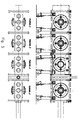
- the substrate heating is in the vacuum coating system "Lindwurm" (internal name) exists, namely a maximum of one in each of the four chambers.
- Half is up the large flange on one side of the chamber and the other mounted on the opposite flange on the other side (see Figure 5, side view).
- the larger Flange concentric flanges hides the sputter source, which in this system is a cylindrical cathode sputtering source is.
- the respective Atomization source creates the flow of material to that of the source facing surface of the substrate to be coated.
- the attachment 5 can therefore have a maximum of four heating devices and eight sputter sources. Depending on the coating process the operation is run accordingly.
- the wafer to be coated is attached to the intended one Front brought into the process space via valves and moved through the chambers on a transport rail in order to removed after the uninterrupted coating process to become, i.e. the system must be used during the entire coating process cannot be opened.
- the plant there is an industrial coating facility with which wafer series diverse, from single coating to multiple coating and can be coated on one or both sides. Wafers up to 5 "in diameter can be processed without interruption become.
- the structure of the substrate heating follows one after the other from the figures 1 to 4. In terms of dimensions, it is exemplary and would have different dimensions for other processes.
- the whole Heating device is mirror-symmetrical, so that the Description of a half explains the structure.
- the heating plate the actual heat source of the heating, is folded into the plane in FIG. 1 and then has a rectangular contour of here 376 mm x 485 mm.
- the circular opening with a radius of 30 mm around the intersection of the horizontal with the vertical axis is being installed for the passage of the material flow from the associated cylinder cathode.
- the two pairs of elongated holes with the 24 x 8.1 mm hole dimension are used to pass through the Al 2 O 3 holding tubes for placing the radiator floor on the bottom of the insulation tray.
- the insulation trough which in Figure 2 folded in the plane Shape is shown, is made of quartz glass. She encased in Assemble the heating plate. In the middle of the floor is the same one and breakthrough of the same size as in the heating plate. in the Quartz glass bottom are still the two circular breakthroughs for the passage of the two electrodes to the heating plate.
- the two End faces of the quartz glass tub are for constructional reasons somewhat pointed. This is for the assembly of the bent to the tub Heating plate to the two electrodes and for space reasons useful.
- Figure 3 shows the installed half of the substrate heater of above.
- the two electrodes are each in an insulating tube and above it in the large flange on the chamber wall applied, positioned. You have an inflow and outflow channel, so that they can also be connected to a cooling circuit.
- the two bare ones protrude through the bottom of the isolation tub Electrodes, at the end of which the frame, the heating plate holder, screwed over two brackets and together with the insulation tray is positioned.
- the shape of the frame is the Heater bracket, easier to see. It has a dual function namely: on the one hand bracket and shape stabilization for the complete heating bath and on the other hand electrical connection to the electrode.
- the heat source, the resistance sheet or the glow plate here made of 0.05 mm thick Alloy 600, stretches the clear width of the insulation trough.
- To the The axis of the power supply is two parallel, mirror-inverted rows of four threaded holes, to which each a stainless steel perforated strip the two outer areas of one Row of holes around the rounded and electrically insulated edge the heating plate holder is pulled electrically conductive be attached.
- the front of the heating plate bracket is also perpendicular to it Row of threaded holes, also on a stainless steel perforated strip the inner area of the row of holes pulled up in front of the electrode Heating plate is attached. Through this screw connection The trough shape of the heating plate is generated for both electrodes. So on the one hand the side walls and on the other hand those from the floor ago strongly rounded end walls (see Figure 3) of the heating plate trough educated.
- the central opening of 60 mm is in the bottom of the glow sheet Diameter with a sheet metal ring on both sides is whose outer larger diameter is 67 mm and outer smaller diameter is 63 mm (see figure 1 on the right Detail).
- the inner diameter is equal to that of the breakthrough, namely 60 mm.
Landscapes
- Chemical & Material Sciences (AREA)
- Engineering & Computer Science (AREA)
- Materials Engineering (AREA)
- Metallurgy (AREA)
- Organic Chemistry (AREA)
- Chemical Kinetics & Catalysis (AREA)
- Mechanical Engineering (AREA)
- Crystallography & Structural Chemistry (AREA)
- Resistance Heating (AREA)
- Exposure Of Semiconductors, Excluding Electron Or Ion Beam Exposure (AREA)
- Physical Vapour Deposition (AREA)
Abstract
Description
- Figur 1
- das in die Ebene geklappte Heizungsblech,
- Figur 2
- die in die Ebene geklappte Isolationswanne,
- Figur 3
- die Draufsicht auf eine Heizungseinrichtung,
- Figur 4
- die Seitenansicht auf eine Heizeinrichtung,
- Figur 5
- die Vakuumbeschichtungsanlage mit 4 Kammern.
Claims (7)
- Substratheizung zum beidseitigen Beheizen eines Wafers in einem von der Umgebung abgeschotteten Prozeßraum, bestehend aus zwei gleichartigen, wannenförmigen Heizeinrichtungen, die spiegelbildlich zueinander stehen und so einen Heizraum, weitestgehend einen Strahlungshohlraum, bilden, wobei die beiden Heizeinrichtungen soweit auseinander stehen, dass der auf einer Transporteinrichtung sitzende, zu prozessierende Wafer gerade hochkant hindurch gezogen werden kann, und die Heizeinrichtung folgendermaßen aufgebaut ist:der wannenförmige Heizkörper aus elektrischem Widerstandsblech bildet, in die Ebene auseinander geklappt, ein zusammenhängendes Blechstück rechteckiger Kontur mit je einer Lochreihe an zwei einander gegenüberliegenden Kanten, von jeder dieser Kanten gehen jeweils zwei gleich lange Einschnitte, ein Einschnittpaar, senkrecht und in vorgegebenem Abstand zueinander sowie zu den andern beiden Rechteckkanten ins Blechinnere, die sich in vorgegebenen Abstand unter Bildung einer zentralen einschnittsfreien Zone, dem Bodenbereich, ebenfalls spiegelbildlich gegenüber liegen,im Zentrum des Bodenbereichs ist ein kreisförmiger Durchbruch vorgegebenen Durchmessers, der auf beiden Bodenseiten je von einem Blechring variierenden Außendurchmessers berandet ist, und zwar ist der Außendurchmesser auf der Längsachse des Bodenbereichs durch den Durchbruchmittelpunkt am kleinsten undwächst zur dazu senkrechten Querachse hin kontinuierlich an, am Fuße der beiden stirnseitigen Bewandungen sind jeweils zwei langlochartige Durchbrüche,das wannenförmig gehaltene Widerstandsblech liegt in einer Isolationswanne aus thermisch hochbeständigem, dielektrischem Material, in deren Boden sich neben dem zentralen Durchbruch mit demselben Durchmesser wie im Widerstandsblech am Rande des stirnseitigen Bodenbereichs zwei weitere Durchbrüche im Blechstück befinden, die bezüglich der Querachse spiegelbildlich zueinander und außerhalb der Wanne aus dem Widerstandsblech liegen, undzwei für die thermische Beanspruchung geeignete, formbeständige Stangen aus dielektrischem Material zur Positionierung des Heizblechs durch die beiden Langlochpaare derartig geschoben sind, dass der Bodenbereich des wannenförmigen Heizkörpers zwischen diesen und dem Boden der Isolationswanne liegt,jede Stirnseite des wannenförmigen Widerstandsblech und die beiden an derselben hinausragenden Enden der Seitenwände sind über Lochleisten an je einen metallischen Rahmen geschraubt, die beiden Stangen sind am Fuße der beiden Rahmen eingelegt unddie derart gebildete wannenförmige Hälfte der Heizeinrichtung ist über Bügel an den beiden Rahmen an zwei durch die beiden Durchbrüche im Boden der Isolationswanne ragenden Stromzuführungen verschraubt und dadurch gleichzeitig positioniert und verankert.
- Substratheizung nach Anspruch 1,
dadurch gekennzeichnet, dass
die Oberfläche des Innenbodens und der Innenwand der Isolationswanne zur Streuung der Wärmestrahlung materialeigen mattiert sind. - Substratheizung nach Anspruch 2,
dadurch gekennzeichnet, dass
der Wandbereich des Prozeßraums, durch den hindurch die beiden Stromzuführungen führen, ein abnehmbarer Flanschdeckel ist. - Substratheizung nach Anspruch 3,
dadurch gekennzeichnet, dass
die Stromzuführungen bis hin zu dem jeweiligen Rahmen Bestandteil eines Kühlmittelkreislaufs sind. - Substratheizung nach Anspruch 4,
dadurch gekennzeichnet, dass
die beiden Heizschalen selbst noch von einer weiteren Reflexions- und Isolationsschale ummantelt sind. - Substratheizung nach Anspruch 5,
dadurch gekennzeichnet, dass
die beiden Blechringe, die den zentralen Durchbruch im Boden des wannenförmigen Heizblechs auf beiden Seiten beranden, den Bereich des durch den Durchbruch in der dortigen Umgebung erzwungenen inhomogenen Stromlinienverlaufs bis höchstens hin zum wieder als homogen anzusehenden Stromlinienverlauf zwischen den beiden Lochreihen, entsprechend der Stromliniendichte dick, überdecken. - Substratheizung nach Anspruch 5,
dadurch gekennzeichnet, dass
die beiden Blechringe, die den zentralen Durchbruch im Boden des wannenförmigen Heizblechs auf beiden Seiten beranden, den Bereich des durch den Durchbruch in der dortigen Umgebung erzwungenen inhomogenen Stromlinienverlaufs teilweise überdecken und die äußere Kontour der beiden Ringe oval oder ellipsenförmig ist.
Applications Claiming Priority (2)
| Application Number | Priority Date | Filing Date | Title |
|---|---|---|---|
| DE10037566 | 2000-08-02 | ||
| DE10037566A DE10037566C2 (de) | 2000-08-02 | 2000-08-02 | Substratheizung zum gleichzeitig beidseitigen Beheizen eines Wafers |
Publications (2)
| Publication Number | Publication Date |
|---|---|
| EP1178520A2 true EP1178520A2 (de) | 2002-02-06 |
| EP1178520A3 EP1178520A3 (de) | 2005-12-07 |
Family
ID=7651016
Family Applications (1)
| Application Number | Title | Priority Date | Filing Date |
|---|---|---|---|
| EP01115992A Withdrawn EP1178520A3 (de) | 2000-08-02 | 2001-06-30 | Substratheizung zum gleichzeitig beidseitigen Beheizen eines Wafers |
Country Status (2)
| Country | Link |
|---|---|
| EP (1) | EP1178520A3 (de) |
| DE (1) | DE10037566C2 (de) |
Cited By (1)
| Publication number | Priority date | Publication date | Assignee | Title |
|---|---|---|---|---|
| CN118725882A (zh) * | 2024-08-12 | 2024-10-01 | 珠海霖泽环保科技有限公司 | 一种生活垃圾制备可燃气的装备及方法 |
Families Citing this family (1)
| Publication number | Priority date | Publication date | Assignee | Title |
|---|---|---|---|---|
| DE10211827C1 (de) * | 2002-03-16 | 2003-10-30 | Karlsruhe Forschzent | Lagerung eines Substrathalterrades mit darin eingebautem/verankertem Substrathalter |
Family Cites Families (3)
| Publication number | Priority date | Publication date | Assignee | Title |
|---|---|---|---|---|
| DE2830589C2 (de) * | 1978-07-12 | 1985-04-18 | Ibm Deutschland Gmbh, 7000 Stuttgart | Durchlaufofen zum Prozessieren von Halbleiterplättchen |
| US4500407A (en) * | 1983-07-19 | 1985-02-19 | Varian Associates, Inc. | Disk or wafer handling and coating system |
| AU5930196A (en) * | 1995-06-07 | 1996-12-30 | Brooks Automation, Inc. | Dual side passive gas substrate thermal conditioning |
-
2000
- 2000-08-02 DE DE10037566A patent/DE10037566C2/de not_active Expired - Fee Related
-
2001
- 2001-06-30 EP EP01115992A patent/EP1178520A3/de not_active Withdrawn
Cited By (1)
| Publication number | Priority date | Publication date | Assignee | Title |
|---|---|---|---|---|
| CN118725882A (zh) * | 2024-08-12 | 2024-10-01 | 珠海霖泽环保科技有限公司 | 一种生活垃圾制备可燃气的装备及方法 |
Also Published As
| Publication number | Publication date |
|---|---|
| EP1178520A3 (de) | 2005-12-07 |
| DE10037566A1 (de) | 2002-02-21 |
| DE10037566C2 (de) | 2002-10-24 |
Similar Documents
| Publication | Publication Date | Title |
|---|---|---|
| DE69513876T2 (de) | Abschirmungs-Anordnung für Vakuumkammer | |
| DE2102352C3 (de) | Hochfrequenzbetriebene Sprühvorrichtung | |
| DE4235953C2 (de) | Sputterquelle mit einer linearen Hohlkathode zum reaktiven Beschichten von Substraten | |
| DE69112506T2 (de) | CVD-Anlage und Verfahren zur Reduzierung der Teilchen-Verseuchung in einem CVD-Verfahren. | |
| DE2026622C2 (de) | Koronareaktorkern zur Ozonerzeugung | |
| DE60036631T2 (de) | Plasmabehandlungsapparatur und plasmabehandlungsverfahren | |
| EP3278355B1 (de) | Waferboot und behandlungsvorrichtung für wafer | |
| EP2010700B1 (de) | Vorrichtung und verfahren zur galvanischen beschichtung | |
| DE10352606B4 (de) | Plasmabehandlungsvorrichtung | |
| DE69836253T2 (de) | Doppelfensterabgasanlage für waferplasmabearbeitungsvorrichtung | |
| DE102006029425B4 (de) | Dichtungsteil und Substrat-bearbeitende Vorrichtung mit einem Dichtungsteil | |
| DE102015004430A1 (de) | Vorrichtung und Verfahren zur Plasmabehandlung von Wafern | |
| DE19635669C1 (de) | Verfahren und Vorrichtung zur Beschichtung von Substraten mittels Gasflußsputtern | |
| DE3639760C2 (de) | ||
| DE69128544T2 (de) | Verfahren und vorrichtung zur sputtenbeschichtung mit rotierender magnetischer kathode | |
| DE102010028958B4 (de) | Substratbehandlungsanlage | |
| DE102009011495A1 (de) | Verfahren und Vorrichtung zur Behandlung von Substraten unter Verwendung einer Gasseparation | |
| DE10037566C2 (de) | Substratheizung zum gleichzeitig beidseitigen Beheizen eines Wafers | |
| DE19955108A1 (de) | Entladungslampe mit verbesserter Temperaturhomogenität | |
| DE202014101468U1 (de) | Prozessiervorrichtung, Beschichtungsvorrichtung und Prozesskammer-Anordnung | |
| DE102010011156B4 (de) | Vorrichtung zur thermischen Behandlung von Halbleitersubstraten | |
| WO2020065425A1 (de) | Prozessmodul und anlage mit wenigstens einem solchen prozessmodul | |
| EP1252647B1 (de) | Einkoppelanordnung für mikrowellenenergie mit impedanzanpassung | |
| DE102004001884A1 (de) | Verdampfungseinrichtung für sublimierende Materialien | |
| DE102023116508B4 (de) | Prozessanordnung, deren Verwendung und Verfahren zur Halbleiterprozessierung |
Legal Events
| Date | Code | Title | Description |
|---|---|---|---|
| PUAI | Public reference made under article 153(3) epc to a published international application that has entered the european phase |
Free format text: ORIGINAL CODE: 0009012 |
|
| AK | Designated contracting states |
Kind code of ref document: A2 Designated state(s): AT BE CH CY DE DK ES FI FR GB GR IE IT LI LU MC NL PT SE TR |
|
| AX | Request for extension of the european patent |
Free format text: AL;LT;LV;MK;RO;SI |
|
| PUAL | Search report despatched |
Free format text: ORIGINAL CODE: 0009013 |
|
| AK | Designated contracting states |
Kind code of ref document: A3 Designated state(s): AT BE CH CY DE DK ES FI FR GB GR IE IT LI LU MC NL PT SE TR |
|
| AX | Request for extension of the european patent |
Extension state: AL LT LV MK RO SI |
|
| AKX | Designation fees paid |
Designated state(s): AT BE CH CY DE DK ES FI FR GB GR IE IT LI LU MC NL PT SE TR |
|
| STAA | Information on the status of an ep patent application or granted ep patent |
Free format text: STATUS: THE APPLICATION IS DEEMED TO BE WITHDRAWN |
|
| 18D | Application deemed to be withdrawn |
Effective date: 20060608 |