EP1178190A1 - Procédé et dispositif de contrôle de la combustion d'un moteur à combustion interne équipé d'un générateur de turbulence variable - Google Patents
Procédé et dispositif de contrôle de la combustion d'un moteur à combustion interne équipé d'un générateur de turbulence variable Download PDFInfo
- Publication number
- EP1178190A1 EP1178190A1 EP01402077A EP01402077A EP1178190A1 EP 1178190 A1 EP1178190 A1 EP 1178190A1 EP 01402077 A EP01402077 A EP 01402077A EP 01402077 A EP01402077 A EP 01402077A EP 1178190 A1 EP1178190 A1 EP 1178190A1
- Authority
- EP
- European Patent Office
- Prior art keywords
- calibrated
- maximum pressure
- combustion
- control
- different
- Prior art date
- Legal status (The legal status is an assumption and is not a legal conclusion. Google has not performed a legal analysis and makes no representation as to the accuracy of the status listed.)
- Granted
Links
Images
Classifications
-
- F—MECHANICAL ENGINEERING; LIGHTING; HEATING; WEAPONS; BLASTING
- F02—COMBUSTION ENGINES; HOT-GAS OR COMBUSTION-PRODUCT ENGINE PLANTS
- F02P—IGNITION, OTHER THAN COMPRESSION IGNITION, FOR INTERNAL-COMBUSTION ENGINES; TESTING OF IGNITION TIMING IN COMPRESSION-IGNITION ENGINES
- F02P17/00—Testing of ignition installations, e.g. in combination with adjusting; Testing of ignition timing in compression-ignition engines
- F02P17/12—Testing characteristics of the spark, ignition voltage or current
-
- F—MECHANICAL ENGINEERING; LIGHTING; HEATING; WEAPONS; BLASTING
- F02—COMBUSTION ENGINES; HOT-GAS OR COMBUSTION-PRODUCT ENGINE PLANTS
- F02B—INTERNAL-COMBUSTION PISTON ENGINES; COMBUSTION ENGINES IN GENERAL
- F02B31/00—Modifying induction systems for imparting a rotation to the charge in the cylinder
- F02B31/04—Modifying induction systems for imparting a rotation to the charge in the cylinder by means within the induction channel, e.g. deflectors
- F02B31/06—Movable means, e.g. butterfly valves
-
- F—MECHANICAL ENGINEERING; LIGHTING; HEATING; WEAPONS; BLASTING
- F02—COMBUSTION ENGINES; HOT-GAS OR COMBUSTION-PRODUCT ENGINE PLANTS
- F02D—CONTROLLING COMBUSTION ENGINES
- F02D35/00—Controlling engines, dependent on conditions exterior or interior to engines, not otherwise provided for
- F02D35/02—Controlling engines, dependent on conditions exterior or interior to engines, not otherwise provided for on interior conditions
- F02D35/021—Controlling engines, dependent on conditions exterior or interior to engines, not otherwise provided for on interior conditions using an ionic current sensor
-
- F—MECHANICAL ENGINEERING; LIGHTING; HEATING; WEAPONS; BLASTING
- F02—COMBUSTION ENGINES; HOT-GAS OR COMBUSTION-PRODUCT ENGINE PLANTS
- F02D—CONTROLLING COMBUSTION ENGINES
- F02D41/00—Electrical control of supply of combustible mixture or its constituents
- F02D41/0002—Controlling intake air
-
- F—MECHANICAL ENGINEERING; LIGHTING; HEATING; WEAPONS; BLASTING
- F02—COMBUSTION ENGINES; HOT-GAS OR COMBUSTION-PRODUCT ENGINE PLANTS
- F02D—CONTROLLING COMBUSTION ENGINES
- F02D41/00—Electrical control of supply of combustible mixture or its constituents
- F02D41/0002—Controlling intake air
- F02D2041/0015—Controlling intake air for engines with means for controlling swirl or tumble flow, e.g. by using swirl valves
-
- Y—GENERAL TAGGING OF NEW TECHNOLOGICAL DEVELOPMENTS; GENERAL TAGGING OF CROSS-SECTIONAL TECHNOLOGIES SPANNING OVER SEVERAL SECTIONS OF THE IPC; TECHNICAL SUBJECTS COVERED BY FORMER USPC CROSS-REFERENCE ART COLLECTIONS [XRACs] AND DIGESTS
- Y02—TECHNOLOGIES OR APPLICATIONS FOR MITIGATION OR ADAPTATION AGAINST CLIMATE CHANGE
- Y02T—CLIMATE CHANGE MITIGATION TECHNOLOGIES RELATED TO TRANSPORTATION
- Y02T10/00—Road transport of goods or passengers
- Y02T10/10—Internal combustion engine [ICE] based vehicles
- Y02T10/12—Improving ICE efficiencies
-
- Y—GENERAL TAGGING OF NEW TECHNOLOGICAL DEVELOPMENTS; GENERAL TAGGING OF CROSS-SECTIONAL TECHNOLOGIES SPANNING OVER SEVERAL SECTIONS OF THE IPC; TECHNICAL SUBJECTS COVERED BY FORMER USPC CROSS-REFERENCE ART COLLECTIONS [XRACs] AND DIGESTS
- Y02—TECHNOLOGIES OR APPLICATIONS FOR MITIGATION OR ADAPTATION AGAINST CLIMATE CHANGE
- Y02T—CLIMATE CHANGE MITIGATION TECHNOLOGIES RELATED TO TRANSPORTATION
- Y02T10/00—Road transport of goods or passengers
- Y02T10/10—Internal combustion engine [ICE] based vehicles
- Y02T10/40—Engine management systems
Definitions
- the invention relates to internal combustion engines, and more particularly the combustion control.
- the invention aims to provide a solution to this problem.
- the invention therefore provides a method of controlling combustion an internal combustion engine equipped with a generator variable turbulence, this generator being controlled from instructions control points calibrated for different operating points of the motor.
- this generator being controlled from instructions control points calibrated for different operating points of the motor.
- one controls said combustion by correcting said control instructions calibrated from a measurement of the ionization current of the gases combustion, and by controlling the variable turbulence generator with these corrected operating instructions.
- the invention thus makes it possible, whatever the operating point of the engine (speed, intake manifold pressure) to obtain the internal aerodynamics most conducive to optimal combustion.
- the invention corrects these calibrated control values of the variable turbulence generator in order to obtain optimal efficiency of the motor.
- Another interesting characteristic of the invention resides in the fact that the measurement of the ionization current of the gases is used of combustion to optimize the influence of the turbulence generator variable on the quality of combustion of a lean mixture.
- the ionization sensors are known and have been the subject already many developments by several car manufacturers, and in particular the applicant. We can cite in this regard the requests French Patent No. 96 10 342 and No. 97 15 967.
- the ionization sensors allow access to various characteristic quantities of combustion such as the angle of maximum pressure (Swedish patent application No. 504,197, or application No. 96/05427) and are used in many combustion control systems in engines with internal combustion, for example to detect rattling (request International Patent No. 89/11087), misfires (patent American No. 5,701,876) or wealth (patent application No. 98/37322, or No. 96/22458).
- the measure combustion gas ionization current has never been used to optimize the influence of a variable turbulence generator on the quality of combustion of a lean mixture.
- a first table containing for different points of engine operation, different calibrated crankshaft angle values each corresponding to a maximum pressure in the chamber of combustion, these different calibrated pressure angle values maximum being worked out in order to obtain the optimal yield of the motor.
- variable turbulence generator is controlled with the setpoint thus corrected.
- the invention also relates to a control device of the combustion of an internal combustion engine equipped with a generator of variable turbulence, comprising control means able to control the generator from control instructions calibrated for different engine operating points.
- the device further includes an ionization probe capable of measuring the current ionization of combustion gases.
- the control means are by elsewhere capable of correcting said calibrated control instructions at from the indications delivered by the ionization probe, and to order the variable turbulence generator with these control instructions corrected.
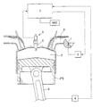
- the reference PS designates a piston of an engine internal combustion, defining with the cylinder in which it slides, a combustion chamber 7 into which a probe opens ionization 6 mounted in a spark plug 5.
- crankshaft angle corresponding to the maximum pressure of the combustion chamber is a good indicator of the quality of combustion and therefore engine performance.
- Reference 4 also designates a conventional sensor allowing to detect the instantaneous value of the crankshaft angle.
- the crankshaft has not been represented but only the piston rod 9 to which it is connected.
- turbulence generator variable which is represented in this figure in a simplified manner by its flap 1 whose position is adjustable in the intake pipe 8. The position of the flap is controlled by a control unit 2.
- Reference 3 also designates an injection computer, to which are connected the control unit 2 of the turbulence generator variable, as well as the sensor 4 for measuring the crankshaft angle.
- the ionization probe 6 is also connected to the computer injection.
- MM memory storing a first table containing for different operating points of the engine (speed, pressure, manifold intake) different values calibrated crankshaft angle each corresponding to a pressure maximum in the combustion chamber.
- This first table is made conventionally to obtain optimal engine performance.
- the memory MM also stores a second table defining, for these same different operating points, the calibrated control instructions for the variable turbulence generator corresponding to said calibrated values of maximum pressure angle. This second table is therefore also calibrated so to obtain optimal engine performance.
- the ionization probe 6, mounted in the spark plug 5, is for example that described in French patent application No. 97 16128.
- the evolution of the ionization current in the combustion chamber, delivered by the ionization probe 6, associated with the value of the instantaneous crankshaft angle delivered by the sensor 4, allows the injection computer to determine a pressure angle value maximum measured, using a well-known calculation algorithm of skilled in the art since the value of the ionization current is proportional to the pressure in the combustion chamber.
- the position of shutter 1 of the turbulence generator is difficult to be adjusted precisely to obtain the desired turbulence rate.
- the injection computer goes, for each operating point considered, apply a correction to the calibrated command setpoint present in the second table, this correction being proportional to the difference between the maximum pressure angle value measured by the probe ionization 6 and that stored in the first calibrated table.
- the invention makes it possible to get as close as possible to the calibrated value of the maximum pressure angle by increasing or decreasing the rate turbulence via the variable turbulence generator, and this, until the value of the maximum pressure angle measured is close (for example to ⁇ 1 ° crankshaft) to the calibrated value corresponding to the operating point considered.
Landscapes
- Engineering & Computer Science (AREA)
- Chemical & Material Sciences (AREA)
- Combustion & Propulsion (AREA)
- Mechanical Engineering (AREA)
- General Engineering & Computer Science (AREA)
- Combined Controls Of Internal Combustion Engines (AREA)
Abstract
Description
- une mémoire apte à stocker une première table contenant pour différents points de fonctionnement du moteur, différentes valeurs calibrées d'angle vilebrequin correspondant chacune à une pression maximale dans le chambre de combustion, ces différentes valeurs calibrées d'angle de pression maximale étant élaborées de façon à obtenir le rendement optimal du moteur, et une deuxième table définissant pour ces mêmes différents points, des consignes de commande calibrées du générateur de turbulence variable correspondant auxdites valeurs calibrées d'angle de pression maximale,
- un calculateur d'injection apte pour chaque point de fonctionnement du moteur, à extraire de la mémoire la consigne de commande calibrée correspondante, à déduire, à partir de la mesure du courant d'ionisation des gaz de combustion effectuée par la sonde d'ionisation, une valeur d'angle de pression maximale mesurée, et à corriger la consigne de commande calibrée extraite en fonction de la différence entre la valeur calibrée d'angle de pression maximale et la valeur d'angle de pression maximale mesurée, et
- un module de commande du générateur de turbulence variable, apte à recevoir ladite consigne de commande corrigée et à commander en conséquence ledit générateur.
Claims (4)
- Procédé de contrôle de la combustion d'un moteur à combustion interne équipé d'un générateur de turbulence variable, ce générateur (1, 2) étant commandé à partir de consignes de commande calibrées pour différents points de fonctionnement du moteur, caractérisé par le fait qu'on contrôle ladite combustion en corrigeant lesdites consignes de commande calibrées à partir d'une mesure du courant d'ionisation des gaz de combustion (6), et en commandant le générateur de turbulence variable avec ces consignes de commande corrigées.
- Procédé selon la revendication 1, caractérisé par le fait qu'on élabore une première table contenant pour différents points de fonctionnement du moteur, différentes valeurs calibrées d'angle vilebrequin correspondant chacune à une pression maximale dans la chambre de combustion, ces différentes valeurs calibrées d'angle de pression maximale étant élaborées de façon à obtenir le rendement optimal du moteur, et on élabore une deuxième table définissant pour ces mêmes différents points de fonctionnement, les consignes de commande calibrées du générateur de turbulence variable correspondant auxdites valeurs calibrées d'angle de pression maximale,
par le fait que pour chaque point de fonctionnement du moteur, on extrait la consigne de commande calibrée correspondante, on mesure (6) le courant d'ionisation des gaz de combustion et on en déduit une valeur d'angle de pression maximale mesurée, et on corrige la consigne de commande calibrée extraite en fonction de la différence entre la valeur calibrée d'angle de pression maximale et la valeur d'angle de pression maximale mesurée, et par le fait qu'on commande (2) le générateur de turbulence variable avec la consigne corrigée. - Dispositif de contrôle de la combustion d'un moteur à combustion interne équipé d'un générateur de turbulence variable, comprenant des moyens de commande aptes à commander le générateur à partir de consignes de commande calibrées pour différents points de fonctionnement du moteur, caractérisé par le fait qu'il comprend en outre une sonde d'ionisation (6) apte à mesurer le courant d'ionisation des gaz de combustion, et par le fait que les moyens de commande sont aptes à corriger lesdites consignes de commande calibrées à partir des indications délivrées par la sonde d'ionisation, et à commander le générateur de turbulence variable (1, 2) avec ces consignes de commande corrigées.
- Dispositif selon la revendication 3, caractérisé par le fait que les moyens de commande comportentune mémoire (MM) apte à stocker une première table contenant pour différents point de fonctionnement du moteur, différentes valeurs calibrées d'angle vilebrequin correspondant chacune à une pression maximale dans la chambre de combustion, ces différentes valeurs calibrées d'angle de pression maximale étant élaborées de façon à obtenir le rendement optimal du moteur, et une deuxième table définissant pour ces mêmes différents points de fonctionnement, des consignes de commande calibrées du générateur de turbulence variable correspondant auxdites valeurs calibrées d'angle de pression maximale,un calculateur d'injection (3) apte pour chaque point de fonctionnement du moteur, à extraire de la mémoire la consigne de commande calibrée correspondante, à déduire, à partir de la mesure du courant d'ionisation des gaz de combustion effectuée par la sonde d'ionisation, une valeur d'angle de pression maximale mesurée, et à corriger la consigne de commande calibrée extraite en fonction de la différence entre la valeur calibrée d'angle de pression maximale et la valeur d'angle de pression maximale mesurée,et un module de commande (2) du générateur de turbulence variable, apte à recevoir ladite consigne de commande corrigée et commander en conséquence ledit générateur.
Applications Claiming Priority (2)
| Application Number | Priority Date | Filing Date | Title |
|---|---|---|---|
| FR0010212A FR2812691B1 (fr) | 2000-08-02 | 2000-08-02 | Procede et dispositif de controle de la combustion d'un moteur a combustion interne equipe d'un generateur de turbulence variable |
| FR0010212 | 2000-08-02 |
Publications (2)
| Publication Number | Publication Date |
|---|---|
| EP1178190A1 true EP1178190A1 (fr) | 2002-02-06 |
| EP1178190B1 EP1178190B1 (fr) | 2006-05-10 |
Family
ID=8853237
Family Applications (1)
| Application Number | Title | Priority Date | Filing Date |
|---|---|---|---|
| EP01402077A Expired - Lifetime EP1178190B1 (fr) | 2000-08-02 | 2001-08-01 | Procédé et dispositif de contrôle de la combustion d'un moteur à combustion interne équipé d'un générateur de turbulence variable |
Country Status (4)
| Country | Link |
|---|---|
| EP (1) | EP1178190B1 (fr) |
| DE (1) | DE60119450T2 (fr) |
| ES (1) | ES2259014T3 (fr) |
| FR (1) | FR2812691B1 (fr) |
Citations (13)
| Publication number | Priority date | Publication date | Assignee | Title |
|---|---|---|---|---|
| WO1989011087A1 (fr) | 1988-05-04 | 1989-11-16 | Robert Bosch Gmbh | Procede de detection de cognements dans des moteurs a combustion interne |
| EP0676533A1 (fr) | 1994-04-09 | 1995-10-11 | Adam Opel Ag | Système de cannaux d'admission pour un moteur à combustion interne |
| WO1996005427A1 (fr) | 1994-08-11 | 1996-02-22 | Mecel Ab | Procede de commande de reglage d'allumage dans les moteurs a combustion |
| JPH0874583A (ja) * | 1994-09-07 | 1996-03-19 | Hitachi Ltd | スワール制御弁の異常診断方法 |
| WO1996022458A1 (fr) | 1995-01-18 | 1996-07-25 | Mecel Ab | Procede et systeme de commande de moteurs a combustion interne |
| US5551392A (en) * | 1993-10-19 | 1996-09-03 | Fuji Jukogyo Kabushiki Kaisha | Engine air intake system |
| US5640941A (en) * | 1995-12-04 | 1997-06-24 | Ford Motor Company | Internal combustion engine with stratified charge and tumble motion |
| US5670715A (en) * | 1995-07-28 | 1997-09-23 | Unisia Jecs Corporation | Method of diagnosing a mechanism for improving combustion in an internal combustion engine and apparatus therefor |
| US5701876A (en) | 1996-06-10 | 1997-12-30 | Mitsubishi Denki Kabushiki Kaisha | Misfire detecting apparatus for internal combustion engine |
| US5787851A (en) | 1993-12-29 | 1998-08-04 | Yamaha Hatsudoki Kabushiki Kaisha | Intake control system |
| WO1998037322A1 (fr) | 1997-02-20 | 1998-08-27 | Adrenaline Research Inc. | Appareil et procede de regulation du rapport air/carburant au moyen de mesures d'ionisation |
| US5904127A (en) * | 1996-10-16 | 1999-05-18 | Daimler-Benz Ag | Method of controlling an adjustable operating parameter of an internal combustion engine with direct fuel injection |
| US5913298A (en) | 1996-12-26 | 1999-06-22 | Yamaha Hatsudoki Kabushiki Kaisha | Valve timing system for engine |
Family Cites Families (3)
| Publication number | Priority date | Publication date | Assignee | Title |
|---|---|---|---|---|
| SE504197C2 (sv) | 1995-05-15 | 1996-12-02 | Mecel Ab | Metod för bestämning av läget för maximalt tryck under en förbränning i en förbränningsmotor |
| FR2752598B1 (fr) | 1996-08-21 | 1998-10-09 | Renault | Procede et dispositif de diagnostic de l'allumage d'un moteur thermique par mesure de l'impedance d'ionisation |
| FR2772435B1 (fr) | 1997-12-16 | 2000-02-18 | Renault | Capteur d'ionisation dans un systeme d'allumage pour moteur a combustion interne |
-
2000
- 2000-08-02 FR FR0010212A patent/FR2812691B1/fr not_active Expired - Fee Related
-
2001
- 2001-08-01 ES ES01402077T patent/ES2259014T3/es not_active Expired - Lifetime
- 2001-08-01 EP EP01402077A patent/EP1178190B1/fr not_active Expired - Lifetime
- 2001-08-01 DE DE60119450T patent/DE60119450T2/de not_active Expired - Lifetime
Patent Citations (13)
| Publication number | Priority date | Publication date | Assignee | Title |
|---|---|---|---|---|
| WO1989011087A1 (fr) | 1988-05-04 | 1989-11-16 | Robert Bosch Gmbh | Procede de detection de cognements dans des moteurs a combustion interne |
| US5551392A (en) * | 1993-10-19 | 1996-09-03 | Fuji Jukogyo Kabushiki Kaisha | Engine air intake system |
| US5787851A (en) | 1993-12-29 | 1998-08-04 | Yamaha Hatsudoki Kabushiki Kaisha | Intake control system |
| EP0676533A1 (fr) | 1994-04-09 | 1995-10-11 | Adam Opel Ag | Système de cannaux d'admission pour un moteur à combustion interne |
| WO1996005427A1 (fr) | 1994-08-11 | 1996-02-22 | Mecel Ab | Procede de commande de reglage d'allumage dans les moteurs a combustion |
| JPH0874583A (ja) * | 1994-09-07 | 1996-03-19 | Hitachi Ltd | スワール制御弁の異常診断方法 |
| WO1996022458A1 (fr) | 1995-01-18 | 1996-07-25 | Mecel Ab | Procede et systeme de commande de moteurs a combustion interne |
| US5670715A (en) * | 1995-07-28 | 1997-09-23 | Unisia Jecs Corporation | Method of diagnosing a mechanism for improving combustion in an internal combustion engine and apparatus therefor |
| US5640941A (en) * | 1995-12-04 | 1997-06-24 | Ford Motor Company | Internal combustion engine with stratified charge and tumble motion |
| US5701876A (en) | 1996-06-10 | 1997-12-30 | Mitsubishi Denki Kabushiki Kaisha | Misfire detecting apparatus for internal combustion engine |
| US5904127A (en) * | 1996-10-16 | 1999-05-18 | Daimler-Benz Ag | Method of controlling an adjustable operating parameter of an internal combustion engine with direct fuel injection |
| US5913298A (en) | 1996-12-26 | 1999-06-22 | Yamaha Hatsudoki Kabushiki Kaisha | Valve timing system for engine |
| WO1998037322A1 (fr) | 1997-02-20 | 1998-08-27 | Adrenaline Research Inc. | Appareil et procede de regulation du rapport air/carburant au moyen de mesures d'ionisation |
Non-Patent Citations (1)
| Title |
|---|
| PATENT ABSTRACTS OF JAPAN vol. 1996, no. 07 31 July 1996 (1996-07-31) * |
Also Published As
| Publication number | Publication date |
|---|---|
| FR2812691B1 (fr) | 2002-10-04 |
| FR2812691A1 (fr) | 2002-02-08 |
| DE60119450T2 (de) | 2006-12-21 |
| DE60119450D1 (de) | 2006-06-14 |
| EP1178190B1 (fr) | 2006-05-10 |
| ES2259014T3 (es) | 2006-09-16 |
Similar Documents
| Publication | Publication Date | Title |
|---|---|---|
| FR2787511A1 (fr) | Procede et dispositif d'egalisation des couples de chaque cylindre d'un moteur | |
| FR2486161A1 (fr) | Procede et systeme pour regler l'avance a l'allumage d'un moteur en fonction de la presence ou de l'absence du cliquetis ou cognement dans ce moteur | |
| FR2524557A1 (fr) | Dispositif de controle de cognement pour un moteur a combustion interne | |
| FR2875548A1 (fr) | Procede et dispositif de commande d'un moteur a combustion interne | |
| FR2843615A1 (fr) | Procede de regulation du processus de combustion d'un moteur a combustion interne a auto-allumage commande | |
| FR2549145A1 (fr) | Procede de commande en boucle fermee de la vitesse au ralenti d'un moteur a combustion interne | |
| WO2010106259A1 (fr) | Procede de determination de l'avance a l'allumage d'un moteur thermique | |
| FR2847619A1 (fr) | Procede de determination de la masse d'air frais, de la masse de gaz residuel et de la masse de gaz totale dans un cylindre d'un moteur a combustion interne | |
| FR2666411A1 (fr) | Procede et appareil pour determiner des caracteristiques de fonctionnement d'un moteur a explosion a alimentation independante des cylindres. | |
| FR2859763A1 (fr) | Procede et dispositif de gestion d'un moteur a combustion interne | |
| EP1178190B1 (fr) | Procédé et dispositif de contrôle de la combustion d'un moteur à combustion interne équipé d'un générateur de turbulence variable | |
| FR2553831A1 (fr) | Procede permettant de commander la valeur de quantites a produire par un moyen de commande du fonctionnement d'un moteur a combustion interne | |
| FR2967728A1 (fr) | Unite de controle de moteur | |
| FR2548272A1 (fr) | Procede de commande d'injection de combustible a l'acceleration d'un moteur a combustion interne a plusieurs cylindres du type a injection sequentielle | |
| FR2853361A1 (fr) | Procede de gestion d'un moteur a combustion interne | |
| FR2548273A1 (fr) | Procede pour commander l'etat de fonctionnement d'un moteur a combustion interne | |
| EP2307868A1 (fr) | Systeme et procede de correction de la mesure d'un capteur de pression avant turbine | |
| FR2837923A1 (fr) | Procede et calculateur pour determiner un reglage de bon fonctionnement d'un moteur a combustion interne | |
| EP1952004B1 (fr) | Procede d'estimation de la masse des gaz enfermee pendant chaque cycle de fonctionnement dans la chambre de combustion d'un cylindre d'un moteur a combustion interne | |
| CN101061297B (zh) | 用于处理加速度计信号以帮助内燃机中燃烧质量控制的系统和方法 | |
| EP2256322B1 (fr) | Influence de la régulation des nox sur le contrôle du bruit moteur dans un moteur à combustion interne | |
| WO2002040840A1 (fr) | Procede et dispositif de commande du fonctionnement d'un moteur a combustion interne a auto-allumage | |
| WO2014095052A1 (fr) | Procédé de détermination du débit d'air recycle et de la quantité d'oxygène disponible a l'entrée d'un cylindre d'un moteur a combustion interne | |
| FR2776066A1 (fr) | Procede de calcul de la pression moyenne indiquee d'un moteur a combustion interne | |
| FR3047517A1 (fr) | Procede de recalage en fonction de la temperature d’un capteur de pression dans une ligne d’admission d’air d’un moteur |
Legal Events
| Date | Code | Title | Description |
|---|---|---|---|
| PUAI | Public reference made under article 153(3) epc to a published international application that has entered the european phase |
Free format text: ORIGINAL CODE: 0009012 |
|
| AK | Designated contracting states |
Kind code of ref document: A1 Designated state(s): AT BE CH CY DE DK ES FI FR GB GR IE IT LI LU MC NL PT SE TR Kind code of ref document: A1 Designated state(s): DE ES GB |
|
| AX | Request for extension of the european patent |
Free format text: AL;LT;LV;MK;RO;SI |
|
| RAP1 | Party data changed (applicant data changed or rights of an application transferred) |
Owner name: RENAULT S.A.S. |
|
| AKX | Designation fees paid | ||
| REG | Reference to a national code |
Ref country code: DE Ref legal event code: 8566 |
|
| 17P | Request for examination filed |
Effective date: 20020806 |
|
| RBV | Designated contracting states (corrected) |
Designated state(s): DE ES GB |
|
| 17Q | First examination report despatched |
Effective date: 20050524 |
|
| GRAP | Despatch of communication of intention to grant a patent |
Free format text: ORIGINAL CODE: EPIDOSNIGR1 |
|
| GRAS | Grant fee paid |
Free format text: ORIGINAL CODE: EPIDOSNIGR3 |
|
| GRAA | (expected) grant |
Free format text: ORIGINAL CODE: 0009210 |
|
| AK | Designated contracting states |
Kind code of ref document: B1 Designated state(s): DE ES GB |
|
| REG | Reference to a national code |
Ref country code: GB Ref legal event code: FG4D Free format text: NOT ENGLISH |
|
| REF | Corresponds to: |
Ref document number: 60119450 Country of ref document: DE Date of ref document: 20060614 Kind code of ref document: P |
|
| GBT | Gb: translation of ep patent filed (gb section 77(6)(a)/1977) |
Effective date: 20060719 |
|
| REG | Reference to a national code |
Ref country code: ES Ref legal event code: FG2A Ref document number: 2259014 Country of ref document: ES Kind code of ref document: T3 |
|
| PLBE | No opposition filed within time limit |
Free format text: ORIGINAL CODE: 0009261 |
|
| STAA | Information on the status of an ep patent application or granted ep patent |
Free format text: STATUS: NO OPPOSITION FILED WITHIN TIME LIMIT |
|
| 26N | No opposition filed |
Effective date: 20070213 |
|
| PGFP | Annual fee paid to national office [announced via postgrant information from national office to epo] |
Ref country code: DE Payment date: 20140821 Year of fee payment: 14 |
|
| PGFP | Annual fee paid to national office [announced via postgrant information from national office to epo] |
Ref country code: GB Payment date: 20140820 Year of fee payment: 14 Ref country code: ES Payment date: 20140826 Year of fee payment: 14 |
|
| REG | Reference to a national code |
Ref country code: DE Ref legal event code: R119 Ref document number: 60119450 Country of ref document: DE |
|
| GBPC | Gb: european patent ceased through non-payment of renewal fee |
Effective date: 20150801 |
|
| PG25 | Lapsed in a contracting state [announced via postgrant information from national office to epo] |
Ref country code: GB Free format text: LAPSE BECAUSE OF NON-PAYMENT OF DUE FEES Effective date: 20150801 Ref country code: DE Free format text: LAPSE BECAUSE OF NON-PAYMENT OF DUE FEES Effective date: 20160301 |
|
| REG | Reference to a national code |
Ref country code: ES Ref legal event code: FD2A Effective date: 20160927 |
|
| PG25 | Lapsed in a contracting state [announced via postgrant information from national office to epo] |
Ref country code: ES Free format text: LAPSE BECAUSE OF NON-PAYMENT OF DUE FEES Effective date: 20150802 |