EP1176700A2 - Embedded magnet type rotor, manufacturing method and mold device - Google Patents
Embedded magnet type rotor, manufacturing method and mold device Download PDFInfo
- Publication number
- EP1176700A2 EP1176700A2 EP01118357A EP01118357A EP1176700A2 EP 1176700 A2 EP1176700 A2 EP 1176700A2 EP 01118357 A EP01118357 A EP 01118357A EP 01118357 A EP01118357 A EP 01118357A EP 1176700 A2 EP1176700 A2 EP 1176700A2
- Authority
- EP
- European Patent Office
- Prior art keywords
- rotor core
- manufacturing device
- rotor
- fitting section
- resinous
- Prior art date
- Legal status (The legal status is an assumption and is not a legal conclusion. Google has not performed a legal analysis and makes no representation as to the accuracy of the status listed.)
- Ceased
Links
- 238000004519 manufacturing process Methods 0.000 title claims abstract description 129
- 238000000034 method Methods 0.000 claims abstract description 28
- 238000002347 injection Methods 0.000 claims description 29
- 239000007924 injection Substances 0.000 claims description 29
- 102100027340 Slit homolog 2 protein Human genes 0.000 description 9
- 101710133576 Slit homolog 2 protein Proteins 0.000 description 9
- 230000002950 deficient Effects 0.000 description 8
- 239000000463 material Substances 0.000 description 7
- 230000003247 decreasing effect Effects 0.000 description 6
- 230000005415 magnetization Effects 0.000 description 6
- 239000011347 resin Substances 0.000 description 6
- 229920005989 resin Polymers 0.000 description 6
- 239000003302 ferromagnetic material Substances 0.000 description 4
- 230000005291 magnetic effect Effects 0.000 description 4
- 238000006073 displacement reaction Methods 0.000 description 3
- 239000011800 void material Substances 0.000 description 3
- 238000010276 construction Methods 0.000 description 2
- 230000000694 effects Effects 0.000 description 2
- XEEYBQQBJWHFJM-UHFFFAOYSA-N Iron Chemical group [Fe] XEEYBQQBJWHFJM-UHFFFAOYSA-N 0.000 description 1
- 229910000831 Steel Inorganic materials 0.000 description 1
- 230000001419 dependent effect Effects 0.000 description 1
- 239000010959 steel Substances 0.000 description 1
Images


Classifications
-
- H—ELECTRICITY
- H02—GENERATION; CONVERSION OR DISTRIBUTION OF ELECTRIC POWER
- H02K—DYNAMO-ELECTRIC MACHINES
- H02K15/00—Processes or apparatus specially adapted for manufacturing, assembling, maintaining or repairing of dynamo-electric machines
- H02K15/02—Processes or apparatus specially adapted for manufacturing, assembling, maintaining or repairing of dynamo-electric machines of stator or rotor bodies
- H02K15/03—Processes or apparatus specially adapted for manufacturing, assembling, maintaining or repairing of dynamo-electric machines of stator or rotor bodies having permanent magnets
-
- Y—GENERAL TAGGING OF NEW TECHNOLOGICAL DEVELOPMENTS; GENERAL TAGGING OF CROSS-SECTIONAL TECHNOLOGIES SPANNING OVER SEVERAL SECTIONS OF THE IPC; TECHNICAL SUBJECTS COVERED BY FORMER USPC CROSS-REFERENCE ART COLLECTIONS [XRACs] AND DIGESTS
- Y10—TECHNICAL SUBJECTS COVERED BY FORMER USPC
- Y10T—TECHNICAL SUBJECTS COVERED BY FORMER US CLASSIFICATION
- Y10T29/00—Metal working
- Y10T29/49—Method of mechanical manufacture
- Y10T29/49002—Electrical device making
- Y10T29/49009—Dynamoelectric machine
-
- Y—GENERAL TAGGING OF NEW TECHNOLOGICAL DEVELOPMENTS; GENERAL TAGGING OF CROSS-SECTIONAL TECHNOLOGIES SPANNING OVER SEVERAL SECTIONS OF THE IPC; TECHNICAL SUBJECTS COVERED BY FORMER USPC CROSS-REFERENCE ART COLLECTIONS [XRACs] AND DIGESTS
- Y10—TECHNICAL SUBJECTS COVERED BY FORMER USPC
- Y10T—TECHNICAL SUBJECTS COVERED BY FORMER US CLASSIFICATION
- Y10T29/00—Metal working
- Y10T29/49—Method of mechanical manufacture
- Y10T29/49002—Electrical device making
- Y10T29/49009—Dynamoelectric machine
- Y10T29/49012—Rotor
Definitions
- This invention relates to an embedded magnet type rotor with a rotor core, a mold device for making an embedded magnet type rotor and a method of making an embedded magnet type rotor.
- an embedded magnet type rotor has been known in which anisotropic resinous magnet is filled in arcuate slits provided in a cylindrical rotor core, circumferentially in regular intervals.
- a metallic mold consisting of an upper and a lower die is used for filling the resinous magnet.
- the lower die has permanent magnets disposed along the outside circumference of the rotor core at intervals the same as those of the slits, and ferromagnetic materials disposed between the permanent magnets, while the upper die is placed on the top of the lower die and has gates through which the resinous magnet is filled in the slits.
- the rotor core is loaded on the lower die, with ends of the arcuate slits directed toward the magnets; resinous magnet is filled in the slits while magnetically orientated, and then the filled resinous magnet is magnetized using a magnetizing device.
- an embedded magnet type rotor has magnetic saliency
- on the rotor core loaded on the metallic mold is exerted a rotation force due to saliency of the magnets of the metallic mold and the rotor core, which may cause rotation of the rotor core within the metallic mold with the result that the gates of the upper die and the slits of the rotor core are displaced, and the flow of the resinous magnet in the slits may change during filling, resulting in defective filling of the resinous magnet in the slits.
- the problem in magnetization is not limited to anisotropic resinous magnet, but the same trouble is found in isotropic resinous magnet as well.
- said objective is solved by an embedded magnet type rotor according to claim 1.
- said objective is solved by a mold device for making an embedded magnet type rotor according to claim 4.
- said objective is solved by a method of making an embedded magnet type rotor according to claim 8.
- Such an embedded magnet type rotor with a rotor core can be use in a rotary electric device such as an electric motor, a generator, or the like.
- a rotary electric device such as an electric motor, a generator, or the like.
- an embedded magnet type rotor made by a process in which resinous magnet is filled in slits provided in a rotor core such as a laminated iron core.
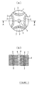
- Fig. 1 shows views of a first embodiment of the embedded magnet type rotor; (a) is a plan view, and (b) is a sectional view taken along line A-A of (a).
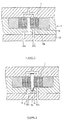
- Fig. 2 shows views of a metallic mold for use in manufacturing the embedded magnet type rotor; (a) is a sectional view, and (b) is a plan view, with the upper die removed.
- Fig. 2(a) corresponds to a sectional view taken along line B-B of (b) in which the upper die is mounted.
- the embedded magnet type rotor of this embodiment is comprised of a rotor core 1, and anisotropic resinous magnet 3 filled in slits 2 provided in the rotor core 1.
- the rotor core 1 as shown in Fig. 1(b), is formed of laminated electromagnetic steel plates, of a disc-like shape, each having a punched-out key hole-like shaft hole 5 with a recess 4 and slits 2, and has a cylindrical shape, as a whole, with a shaft hole 5 and slits 2 therethrough in the axial direction.
- the slits 2 are formed in the shape of an arc in the rotor core 1 circumferentially at regular intervals, and resinous magnet 3 is filled therein.
- a metallic mold 7 is used, as shown in Fig. 2(a), which is comprised of an upper die 8, an intermediate die 9, and a lower die 10.
- the upper die 8 has gates 11 through which the resinous magnet 3 is injected into the slits 2 of the rotor core 1; and the intermediate die 9, as shown in Fig. 2(b), is provided, at its center, with a space in which the rotor core 1 is loaded, and has permanent magnets 12 disposed, along the outside circumference of the rotor core 1 loaded in the space, at intervals the same as those of the slits 2, ferromagnetic materials 13 between the permanent magnets 12, and a nonmagnetic material surrounding the permanent magnets 12 and the ferromagnetic materials 13.
- a key-shaped core pin 16 formed with a projecting portion 15, engageable with the recessed portion 4 of the rotor core, along the axial line, which core pin 16 is adapted to be inserted into the rotor core 1 loaded on the intermediate die 9, so that rotation of the rotor core 1 within the metallic mold 7 can be prevented, and as shown in Fig. 2(b), the rotor core 1 can be held in place in the mold, with ends of the arcuate slits 2 directed toward the permanent magnets 12 for orientation and magnetization.
- the lower die 10 as shown in Fig. 2(a), is formed in the shape of a flat plate, and adapted to support the upper die 8, intermediate die 9, and core pin 16 on its top.
- the metallic mold 7 is arranged such that it is provided with pin holes 18 through which ejector pins 17 can be inserted therein from below, and the tips of the ejector pins 17 are brought into abutment against the bottom of the rotor core 1 loaded on the intermediate die 9.
- the resinous magnet 3 is injected into the slits 2 of the rotor core 1 loaded on the intermediate die 9 while magnetically orientated.
- the core pin 16 is inserted in the shaft hole 5 of the rotor core 1 to load the rotor core 1 on the intermediate die 9 with the ends of the arcuate slits 2 directed toward the permanent magnets 12 of the metallic mold 7, and as shown in Fig. 2(a), the tips of the ejector pins 17 are brought into abutment against the bottom of the rotor core 1.
- the upper die 8 is placed on the top of the intermediate die 9 and thereafter, the resinous magnet 3 is injected into the slits 2 of the rotor core 1 from the gates 11 of the upper die 8 while magnetically orientated by the permanent magnets 12 of the metallic mold 7.
- the upper die 8 is removed from the top of the intermediate die 9, and the rotor core 1 is pushed up with the ejector pins 17 to take out the rotor core 1 from the intermediate die 9.
- the metallic mold 7 for use in a process in which the resinous magnet is filled while magnetically orientated is exemplified as a manufacturing device
- the manufacturing device may be one for use in a process in which magnets embedded in a rotor core are magnetized, in which case, rotation of the rotor core 1 due to a magnetization current can also be prevented.
- Fig. 3 is a view showing a second embodiment of the embedded magnet type rotor, a plan view similar to Fig. 2(b). Like parts as in the first embodiment are designated by like numerals.
- the arrangement of this embodiment is different from that of the first embodiment in that in the outside circumferential surface of the rotor core 1 are provided a plurality of grooves 4a running from one end of the rotor core 1 to the other end, as recessed portions, and on the inside circumferential surface of the ferromagnetic materials 13 of the intermediate die 9, are provided a plurality of ribs 15a engageable with the grooves 4a.
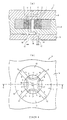
- Fig. 4 is a view showing a third embodiment of the embedded magnet type rotor, a sectional view similar to Fig. 2 (a). Like parts as in the first embodiment are designated by like numerals.
- the arrangement of this embodiment is different from that of the first embodiment in that in one end of the rotor core 1 is provided a hole 4b as a recessed portion, and a projection 15b is provided on the bottom of the cavity of the intermediate die 9.
- Fig. 5 is a view showing a fourth embodiment of the embedded magnet type rotor, a sectional view similar to Fig. 2(a). Like parts as in the first embodiment are designated by like numerals.
- the arrangement of this embodiment is different from those of the foregoing embodiments in that instead of a recessed portion provided directly in the rotor core, a shaft 19 provided, at one end, with a groove 4c as a recessed portion, is press fitted into the shaft hole 5 of the rotor core 1, and in the bottom of the cavity of the intermediate die 9 is formed a hole 20 with a rib 15c engageable with the groove 4c of the shaft 19.
- Fig. 6 is a view showing a fifth embodiment of the embedded magnet type rotor, showing, like Fig. 2, a metallic die for use in manufacturing the embedded magnet type rotor; (a) is a sectional view, and (b) is a plan view, with the upper die removed.
- the arrangement of this embodiment is different from those of the foregoing embodiments in that instead of a recessed portion provided in the rotor core 1 or the shaft 19, the slits 2 are utilized as recessed portions, and ejector pins 17 are used which are slidable in the slits 2.
- the core pin 16 is inserted in the shaft hole 5 of the rotor core 1; the ejector pins 1 are inserted in the slits 2 of the rotor core 1 to the upper ends; and as shown in Fig. 6(a), the rotor core 1 is loaded on the intermediate die 9, with the ends of the arcuate slits 2 directed toward the permanent magnets 12 of the metallic mold 7.
- the ejector pins 17 are inserted in the slits in this way, so that rotation of the rotor core 1 can be prevented, and alignment of the slits 2 and the gates 11 can be achieved.
- the resinous magnet 3 is injected into slits 2 of the rotor core 1 from the gates 11 of the upper die 8 while magnetically orientated by the permanent magnets 12 of the metallic mold 7, and the ejector pins 17 are moved downward in response to the amount of resinous magnet injected.
- the movement of the ejector pins 17 is stopped with their tips left in the slits; after the resinous magnet 3 injected into the slits 2 has been solidified, the upper die 8 is removed from the top of the intermediate die 9; and then the solidified resinous magnets 3 are pushed up with the ejector pins 17 to take out the rotor core 1 from the intermediate die 9.
- the contact areas of the ejector pins 17 with the solidified resinous magnets 3 are sufficiently large, the ejector pins 17 rarely cut into, or leave their marks on, the contact surface of the solidified resinous magnets 3.
- a recessed portion 4 is provided in the rotor core 1, running from one end to the other end thereof, but it may be one running from one end of the rotor core 1 to the middle thereof.
- a projection 15 is provided in the metallic mold 7, corresponding to a recess 4 provided in the rotor core 1, but the projection may be provided on the metallic mold 7 if engageable with the recess in the rotor 1.
- a recessed portion 4 is provided on the rotor core 1 side, and a projecting portion 15 on the metallic mold 7 side, but conversely, the projecting portion may be provided on the rotor core 1 side, and the recessed portion on the metallic mold 7 side.
- anisotropic resinous magnet 3 may be filled without orientation, in which case, although no rotation force due to orientating magnetic field is produced, the resinous magnet may be used as a means of aligning the slits 2 and the gates 11 and also as a means of stopping rotation in a process of magnetization.
- slits 2 are provided in the rotor core 1, one for each pole, arrangements of the foregoing embodiments are not intended to limit the number of the slits 2, and a plurality of layers of slits may be provided.
- the shape of the slits 2 is not limited, and it may be, for example, rectangular.
- an embedded permanent magnet type metallic mold is used as an orientating metallic mold
- a magnetized coil type metallic mold may be used in which orientating magnetic field is generated by electromagnets.
- the respective rotor core fitting sections engageable with the respective manufacturing device fitting sections can be combined with each other.
- the recess 4 and the projecting portion 15 as shown in Figs. 1 and 2 can be combined with the grooves 4a and the ribs 15a as shown in Fig. 3 within one embodiment.
- other combinations of two or more embodiments mentioned above are possible.
- the embedded magnet type rotor is an embedded magnet type rotor made by a process in which resinous magnet is filled in slits provided in a rotor core, wherein a rotor core side fitting section engageable with a manufacturing device side fitting section provided in a manufacturing device for use in orientating or magnetizing process of the resinous magnet, is provided, so that the rotor core side fitting section can be engaged with the manufacturing device side fitting section, preventing rotation of the rotor core within the manufacturing device.
- ejector pins slidable along the inner surfaces of spaces to be filled are inserted in the spaces to their injection mouths, so that no displacement of the injection mouths is produced, and injection material can be filled in the spaces to be filled, without trouble. Further, the ejector pins can be moved in the direction of retraction in association with injection of the injection material, to thereby decrease pressure inside the die for a function of drawing the resin from the injection mouths, so that injection pressure of the resin can be kept low, preventing deformation of the die, and the resin can be filled in the die almost perfectly without void, resulting in an increased filling efficiency.
- the embedded magnet type rotor is made by a process in which resinous magnet is filled in slits provided in a rotor core, wherein in an inside circumferential surface of a shaft hole formed in said rotor core is provided a rotor core side fitting section engageable with a manufacturing device side fitting section formed in a manufacturing device for use in an orientating or a magnetizing process of said resinous magnet.
- the embedded magnet type rotor is made by a process in which resinous magnet is filled in slits provided in a rotor core, wherein in an outside circumferential surface of said rotor core is provided a rotor core side fitting section engageable with a manufacturing device side fitting section formed in a manufacturing device for use in an orientating or a magnetizing process of said resinous magnet.
- a recessed or a projecting portion may be provided as the rotor core side fitting section.
- a groove may be provided running from one end of the rotor core to the middle thereof or running from one end to the other end of the rotor core.
- the manufacturing device side fitting section may be provided with a projecting portion engageable with the recessed portion of the rotor core, for example, a rib extending from one end of the rotor core to the middle thereof or extending from one end to the other end of the rotor core, corresponding to the shape of the groove of the rotor core, or a projection adapted to be protruded within the groove of the rotor core.
- a projecting portion engageable with the recessed portion of the rotor core, for example, a rib extending from one end of the rotor core to the middle thereof or extending from one end to the other end of the rotor core, corresponding to the shape of the groove of the rotor core, or a projection adapted to be protruded within the groove of the rotor core.
- a projecting portion may be provided as the rotor core side fitting section, and a recessed portion as the manufacturing device side fitting section.
- the embedded magnet type rotor is made by a process in which resinous magnet is filled in slits provided in a rotor core, wherein in at least one of end faces of said rotor core is provided a rotor core side fitting section engageable with a manufacturing device side fitting section formed in a manufacturing device for use in an orientating or a magnetizing process of said resinous magnet.
- the rotor core side fitting section is engaged with the manufacturing device side fitting section, so that rotation of the rotor core within the manufacturing device can be prevented. Therefore, the resinous magnet can be filled in the slits without trouble, and the resinous magnet can be orientated and magnetized reliably, resulting in a decreased defective rate.
- a recessed or a projecting portion may be provided as the rotor core side fitting section.
- a hole may be provided, or a groove may be provided running from the shaft hole of the rotor core to the outside circumference thereof.
- the manufacturing device side fitting section may be provided with a projecting portion engageable with the recessed portion of the rotor core, for example, a projection, or a rib extending from the shaft hole of the rotor core to the outside circumference thereof.
- the groove may be provided as the rotor core side fitting section, and the projection projecting within the groove, as the manufacturing device side fitting section.
- a projecting portions engageable with the slits may be provided on the manufacturing device side.
- a projecting portion may be provided as the rotor core side fitting section, and a recessed portion as the manufacturing side fitting section.
- the embedded magnet type rotor is made by a process in which resinous magnet is filled in slits provided in a rotor core, wherein said rotor core is provided with a shaft, and in at least one end of said shaft is provided a rotor core side fitting section engageable with a manufacturing device side fitting section formed in a manufacturing device for use in an orientating or a magnetizing process of said resinous magnet.
- the shaft side fitting section of a shaft provided in the rotor core is engaged with the manufacturing device side fitting section, so that rotation of the rotor core within the manufacturing device can be prevented. Therefore, the resinous magnet can be filled in the slits without trouble, as in the other embodiments, and the resinous magnet can be orientated and magnetized reliably, resulting in a decreased defective rate.
- An embodiment described above teaches a method on filling resinous magnet in slits provided in a rotor core, wherein said resinous magnet is filled in said slits, with ejector pins inserted in said slits.
- the resinous magnet can be filled in the slits, with ejector pins inserted in the slits of the rotor core, so that rotation of the rotor core within the manufacturing device can be prevented. Therefore, the resinous magnet can be filled in the slits without trouble, as in the other embodiments, and the resinous magnet can be orientated reliably, resulting in a decreased defective rate.
- the ejector pin may have any shape, for example, a bar-like one, or have an outside circumference the same as the shape of the inside circumference of the slit.
- the tips of the ejector pins may be inserted in the slits shallowly, or to the middle thereof, or deeply to the injection mouths of the slits.
- the ejector pins may be actively drawn out, or automatically retracted by injection pressure of the resinous magnet.
- the embodiment described above teaches a method on filling resinous magnet in slits provided in a rotor core, wherein after ejector pins slidable along the inner surfaces of spaces to be filled, have been inserted in said spaces to the injection mouths thereof, injection material is injected from said injection mouths, and said ejector pins are moved in the direction of retraction in association with injection of the injection material.
- the ejector pins are slidable along the inner surfaces of the spaces to be filled, and are inserted in the spaces to the injection mouths thereof, so that no displacement of the mouths is produced, and the injection material can be filled in the spaces to be filled, without trouble.
- the ejector pins can be moved in the direction of retraction in association with injection of the injection material, to thereby decrease pressure inside the die for a function of drawing the resin from the injection mouths, so that injection pressure of the resin can be kept low, preventing deformation of the die, and the resin can be filled in the die almost perfectly without void, resulting in an increased filling efficiency.
- the embodiments described above teaches an embedded magnet type rotor with a rotor core 1 having slits 2 filled with resinous magnet 3.
- Said rotor core 1 is provided a rotor core fitting section 4,4a,4b,4c engageable with a manufacturing device fitting section 15,15a,15b,15c formed in a manufacturing device 7-10,16 for use in an orientating and/or a magnetizing process of said resinous magnet 3.
- Said rotor core 1 is provided with a shaft hole 5 and an inside circumferential surface of said shaft hole 5 is provided with said rotor core fitting section 4 engageable with the manufacturing device fitting section 15 formed in the manufacturing device 7-10, 16. Additionally or alternatively, an outside circumferential surface of said rotor core 1 is provided with said rotor core fitting section 4a engageable with the manufacturing device fitting section 15a formed in the manufacturing device 7-10,16. Additionally or alternatively, at least one of end faces of said rotor core 1 is provided with said rotor core fitting section 4b engageable with the manufacturing device fitting section 15b formed in the manufacturing device 7-10,16. Additionally or alternatively said rotor core 1 is provided with a shaft 19 and at least one end of said shaft 19 is provided with said rotor core fitting section 4c engageable with the manufacturing device fitting section (15c) formed in the manufacturing device 7-10,16.
- Said rotor core fitting section is at least one recess 4 extending along the inside circumferential surface of said shaft hole 5 and said manufacturing device fitting section is at least one projection 15 extending along a core pin 16 of the manufacturing device being inserted into the shaft hole 5 of the rotor core 1 during manufacturing process.
- said rotor core fitting section is at least one groove 4a extending along the outside circumferential surface of said rotor core 1 and said manufacturing device fitting section 15a is at least one rib 15a extending along an inside circumferential surface of a die 9 of the manufacturing device and being inserted into the groove 4a of the rotor core 1 during manufacturing process.
- said rotor core side fitting section is at least one hole 4b provided in at least one end face of said rotor core 1 and said manufacturing device fitting section is at least one projection 15b provided on a surface of a die 9 of the manufacturing device and being inserted into the hole 4b of the rotor core 1 during manufacturing process.
- said rotor core fitting section is at least one groove 4c provided on at least one end the shaft 19 of the rotor core 1 and said manufacturing device fitting section is at least one rib 15c provided on a surface of a die 9 of the manufacturing device and being inserted into the groove 4c of the shaft 19 during manufacturing process.
- the embodiments described above teaches also a mold device for making an embedded magnet type rotor with a rotor core 1 having slits 2 filled with resinous magnet 3.
- a manufacturing device fitting means 15,15a,15b,15c,17,18 is formed in a manufacturing device 7-10,16 of said mold device engageable with fitting means 2,4,4a,4b,4c of the rotor core 1 for use in an orientating and/or a magnetizing process of said resinous magnet 3.
- Said manufacturing device fitting means 15 is engageable with the fitting means 4 of the rotor core 1 provided on an inside circumferential surface of shaft hole 5 of the rotor core 1. Additionally or alternatively said manufacturing device fitting means 15a is engageable with the fitting means 4a of the rotor core 1 provided on an outside circumferential surface of said rotor core 1. Additionally or alternatively said manufacturing device fitting means 15b is engageable with the fitting means 4b of the rotor core 1 provided on at least one of end faces of said rotor core 1. Additionally or alternatively said manufacturing device fitting means 15c is engageable with the fitting means 4c of the rotor core 1 provided on a shaft 19 of the rotor core 1.
- Said manufacturing device fitting means is at least one projection 15 extending along a core pin 16 of the manufacturing device and the said fitting means of the rotor core 1 is at least one recess 4 extending along the inside circumferential surface of said shaft hole 5 and said projection of the core pin 16 of the manufacturing device is inserted into the recess 4 of the shaft hole 5 of the rotor core 1 during manufacturing process.
- said manufacturing device fitting means is at least one rib 15a extending along an inside circumferential surface of a die 9 of the manufacturing device and said fitting means of the rotor core 1 is at least one groove 4a extending along the outside circumferential surface of said rotor core 1 and said rib 15a is inserted into the groove 4a of the rotor core 1 during manufacturing process.
- said manufacturing device fitting means is at least one projection 15b provided on a surface of a die 9 of the manufacturing device and fitting means of the rotor core 1 is at least one hole 4b provided in at least one end face of said rotor core 1 and said projection 15b is inserted into the hole 4b of the rotor core 1 during manufacturing process.
- said manufacturing device fitting means is at least one rib 15c provided on a surface of a die 9 of the manufacturing device and said fitting means of the rotor core 1 is at least one groove 4c provided on at least one end the shaft 19 of the rotor core 1 and said rib 15c is inserted into the groove 4c of the shaft 19 during manufacturing process.
- said manufacturing device fitting means comprises at least one pin 17 slidably received in a guide opening 18 of the manufacturing device 9, 10. Said pin 17 is insertable into at least one slit 2 of the rotor core 1 serving as the fitting means of the rotor core 1 and said pin 17 is removable from said slit 2 in association with injection of with resinous magnet 3 into said slit 2.
- Said method further comprises inserting said pin 17 slidable into a slit 2, injecting resinous magnet 3 into said slit 2 by an injection mouth, retracting said pin 17 from the slit 2 in association with injection of the resinous magnet 3. Furthermore said method comprises moving said pin 17 in direction to said slit 2 after said resinous magnet 3 injected into said slit 2 is solidified in order to eject the rotor core 1 from said mold device.
Landscapes
- Engineering & Computer Science (AREA)
- Manufacturing & Machinery (AREA)
- Power Engineering (AREA)
- Permanent Field Magnets Of Synchronous Machinery (AREA)
- Manufacture Of Motors, Generators (AREA)
- Iron Core Of Rotating Electric Machines (AREA)
Abstract
Description
- This invention relates to an embedded magnet type rotor with a rotor core, a mold device for making an embedded magnet type rotor and a method of making an embedded magnet type rotor.
- Heretofore, an embedded magnet type rotor has been known in which anisotropic resinous magnet is filled in arcuate slits provided in a cylindrical rotor core, circumferentially in regular intervals.
- In manufacturing the conventional embedded magnet type rotor, a metallic mold consisting of an upper and a lower die is used for filling the resinous magnet. The lower die has permanent magnets disposed along the outside circumference of the rotor core at intervals the same as those of the slits, and ferromagnetic materials disposed between the permanent magnets, while the upper die is placed on the top of the lower die and has gates through which the resinous magnet is filled in the slits.
- The rotor core is loaded on the lower die, with ends of the arcuate slits directed toward the magnets; resinous magnet is filled in the slits while magnetically orientated, and then the filled resinous magnet is magnetized using a magnetizing device.
- However, since an embedded magnet type rotor has magnetic saliency, in the conventional embedded magnet type rotor, on the rotor core loaded on the metallic mold is exerted a rotation force due to saliency of the magnets of the metallic mold and the rotor core, which may cause rotation of the rotor core within the metallic mold with the result that the gates of the upper die and the slits of the rotor core are displaced, and the flow of the resinous magnet in the slits may change during filling, resulting in defective filling of the resinous magnet in the slits.
- Even if the resinous magnet can be filled in the slits without trouble, displacement of the rotor core from the initial position during loading will prevent proper orientation of the resinous magnet, resulting in a high rate of misorientation. In addition, reluctance torque due to a magnetization current is produced in a magnetizing process, which may cause rotation of the rotor core within the magnetizing device, resulting in high defective rate of magnetization.
- The problem in magnetization is not limited to anisotropic resinous magnet, but the same trouble is found in isotropic resinous magnet as well.
- It is an objective of the present invention to provide an embedded magnet type rotor, a mold device for making an embedded magnet type rotor and a method of making an embedded magnet type rotor, wherein rotation of the rotor core within a manufacturing device is prevented.
- According to a first aspect of the present invention, said objective is solved by an embedded magnet type rotor according to
claim 1. - According to a second aspect of the present invention, said objective is solved by a mold device for making an embedded magnet type rotor according to
claim 4. - According to a method aspect of the present invention, said objective is solved by a method of making an embedded magnet type rotor according to
claim 8. - Preferred embodiments are laid down in the respective dependent claims.
- Such an embedded magnet type rotor with a rotor core can be use in a rotary electric device such as an electric motor, a generator, or the like. Particularly, such an embedded magnet type rotor made by a process in which resinous magnet is filled in slits provided in a rotor core such as a laminated iron core.
- In the following, the present invention is explained in greater detail with respect to several embodiments thereof in conjunction with the accompanying drawings, wherein:
- Fig. 1
- shows views of a first embodiment of the embedded magnet type rotor; (a) is a plan view, and (b) is a sectional view taken along line A-A of (a);
- Fig. 2
- shows views of a metallic mold for use in manufacturing the embedded magnet type rotor; (a) is a sectional view taken along line B-B of (b) in which the upper die is mounted, and (b) is a plan view, with the upper die removed;
- Fig. 3
- is a view showing a second embodiment of the embedded magnet type rotor, a plan view similar to Fig. 2(b);
- Fig. 4
- is a view showing a third embodiment of the embedded magnet type rotor, a sectional view similar to Fig. 2(a);
- Fig. 5
- is a view showing a fourth embodiment of the embedded magnet type rotor, a sectional view similar to Fig. 2 (a); and
- Fig. 6
- shows views of a fifth embodiment of the embedded magnet type rotor; like Fig. 2, (a) is a sectional view taken along line C-C of (b) in which the upper die is mounted, and (b) is a plan view, with the upper die removed.
- Now, a first embodiment of the embedded magnet type rotor will be described with reference to the drawings.
- Fig. 1 shows views of a first embodiment of the embedded magnet type rotor; (a) is a plan view, and (b) is a sectional view taken along line A-A of (a). Fig. 2 shows views of a metallic mold for use in manufacturing the embedded magnet type rotor; (a) is a sectional view, and (b) is a plan view, with the upper die removed. Fig. 2(a) corresponds to a sectional view taken along line B-B of (b) in which the upper die is mounted.
- As shown in Fig. 1(a), the embedded magnet type rotor of this embodiment is comprised of a
rotor core 1, and anisotropicresinous magnet 3 filled inslits 2 provided in therotor core 1. - The
rotor core 1, as shown in Fig. 1(b), is formed of laminated electromagnetic steel plates, of a disc-like shape, each having a punched-out key hole-like shaft hole 5 with arecess 4 andslits 2, and has a cylindrical shape, as a whole, with ashaft hole 5 and slits 2 therethrough in the axial direction. - The
slits 2 are formed in the shape of an arc in therotor core 1 circumferentially at regular intervals, andresinous magnet 3 is filled therein. - In filling the
resinous magnet 3, ametallic mold 7 is used, as shown in Fig. 2(a), which is comprised of anupper die 8, anintermediate die 9, and alower die 10. - The
upper die 8 hasgates 11 through which theresinous magnet 3 is injected into theslits 2 of therotor core 1; and theintermediate die 9, as shown in Fig. 2(b), is provided, at its center, with a space in which therotor core 1 is loaded, and haspermanent magnets 12 disposed, along the outside circumference of therotor core 1 loaded in the space, at intervals the same as those of theslits 2,ferromagnetic materials 13 between thepermanent magnets 12, and a nonmagnetic material surrounding thepermanent magnets 12 and theferromagnetic materials 13. - In the
intermediate die 9, as shown in Fig. 2(a), is inserted from below a key-shaped core pin 16 formed with a projectingportion 15, engageable with therecessed portion 4 of the rotor core, along the axial line, whichcore pin 16 is adapted to be inserted into therotor core 1 loaded on theintermediate die 9, so that rotation of therotor core 1 within themetallic mold 7 can be prevented, and as shown in Fig. 2(b), therotor core 1 can be held in place in the mold, with ends of thearcuate slits 2 directed toward thepermanent magnets 12 for orientation and magnetization. - The
lower die 10, as shown in Fig. 2(a), is formed in the shape of a flat plate, and adapted to support theupper die 8,intermediate die 9, andcore pin 16 on its top. - The
metallic mold 7 is arranged such that it is provided withpin holes 18 through whichejector pins 17 can be inserted therein from below, and the tips of theejector pins 17 are brought into abutment against the bottom of therotor core 1 loaded on theintermediate die 9. - With the construction of the
metallic mold 7 described above, theresinous magnet 3 is injected into theslits 2 of therotor core 1 loaded on theintermediate die 9 while magnetically orientated. - Now, the procedure will be described of filling the
resinous magnet 3 in theslits 2 of therotor core 1 using themetallic mold 7. - First, as shown in Fig. 2(b), the
core pin 16 is inserted in theshaft hole 5 of therotor core 1 to load therotor core 1 on theintermediate die 9 with the ends of thearcuate slits 2 directed toward thepermanent magnets 12 of themetallic mold 7, and as shown in Fig. 2(a), the tips of theejector pins 17 are brought into abutment against the bottom of therotor core 1. - Then, the
upper die 8 is placed on the top of theintermediate die 9 and thereafter, theresinous magnet 3 is injected into theslits 2 of therotor core 1 from thegates 11 of theupper die 8 while magnetically orientated by thepermanent magnets 12 of themetallic mold 7. - After the
resinous magnet 3 injected into theslits 2 has been solidified, theupper die 8 is removed from the top of theintermediate die 9, and therotor core 1 is pushed up with theejector pins 17 to take out therotor core 1 from theintermediate die 9. - As described above, as a result of magnetic orientation being performed with the projecting
portion 15 of thecore pin 16 fitted in therecessed portion 4 of therotor core 1, rotation of therotor core 1 within themetallic mold 7 can be prevented, so that theresinous magnet 3 can be filled in theslits 2 without trouble, and theresinous magnet 3 filled in theslits 2 can be orientated reliably, providing a reduced defective rate. - In the foregoing embodiment, although the
metallic mold 7 for use in a process in which the resinous magnet is filled while magnetically orientated, is exemplified as a manufacturing device, the manufacturing device may be one for use in a process in which magnets embedded in a rotor core are magnetized, in which case, rotation of therotor core 1 due to a magnetization current can also be prevented. - Fig. 3 is a view showing a second embodiment of the embedded magnet type rotor, a plan view similar to Fig. 2(b). Like parts as in the first embodiment are designated by like numerals.
- As shown in Fig. 3, the arrangement of this embodiment is different from that of the first embodiment in that in the outside circumferential surface of the
rotor core 1 are provided a plurality ofgrooves 4a running from one end of therotor core 1 to the other end, as recessed portions, and on the inside circumferential surface of theferromagnetic materials 13 of theintermediate die 9, are provided a plurality ofribs 15a engageable with thegrooves 4a. - The function and the effect of this embodiment are the same as those of the first embodiment.
- Fig. 4 is a view showing a third embodiment of the embedded magnet type rotor, a sectional view similar to Fig. 2 (a). Like parts as in the first embodiment are designated by like numerals.
- As shown in Fig. 4, the arrangement of this embodiment is different from that of the first embodiment in that in one end of the
rotor core 1 is provided ahole 4b as a recessed portion, and aprojection 15b is provided on the bottom of the cavity of theintermediate die 9. - The function and the effect of this embodiment are the same as those of the first embodiment.
- Fig. 5 is a view showing a fourth embodiment of the embedded magnet type rotor, a sectional view similar to Fig. 2(a). Like parts as in the first embodiment are designated by like numerals.
- As shown in Fig. 5, the arrangement of this embodiment is different from those of the foregoing embodiments in that instead of a recessed portion provided directly in the rotor core, a
shaft 19 provided, at one end, with agroove 4c as a recessed portion, is press fitted into theshaft hole 5 of therotor core 1, and in the bottom of the cavity of theintermediate die 9 is formed ahole 20 with arib 15c engageable with thegroove 4c of theshaft 19. - Fig. 6 is a view showing a fifth embodiment of the embedded magnet type rotor, showing, like Fig. 2, a metallic die for use in manufacturing the embedded magnet type rotor; (a) is a sectional view, and (b) is a plan view, with the upper die removed.
- As shown in Fig. 6(a), the arrangement of this embodiment is different from those of the foregoing embodiments in that instead of a recessed portion provided in the
rotor core 1 or theshaft 19, theslits 2 are utilized as recessed portions, andejector pins 17 are used which are slidable in theslits 2. - With the construction of this embodiment as described above, the procedure of filling the
resinous magnet 3 in theslits 2 is different from those of the foregoing embodiments, which will be described in the following. - First, as shown in Fig. 6(b), the
core pin 16 is inserted in theshaft hole 5 of therotor core 1; theejector pins 1 are inserted in theslits 2 of therotor core 1 to the upper ends; and as shown in Fig. 6(a), therotor core 1 is loaded on theintermediate die 9, with the ends of thearcuate slits 2 directed toward thepermanent magnets 12 of themetallic mold 7. - The
ejector pins 17 are inserted in the slits in this way, so that rotation of therotor core 1 can be prevented, and alignment of theslits 2 and thegates 11 can be achieved. - After the
upper die 8 is placed on the top of theintermediate die 9, theresinous magnet 3 is injected intoslits 2 of therotor core 1 from thegates 11 of theupper die 8 while magnetically orientated by thepermanent magnets 12 of themetallic mold 7, and theejector pins 17 are moved downward in response to the amount of resinous magnet injected. As a result of the ejector pins being moved downward in association with injection of theresinous magnet 3, pressure inside theslits 2 can be decreased and thus a function of drawing theresinous magnet 3 from thegates 11 of theupper die 8 can be effected, so that injection pressure of theresinous magnet 3 can be kept low to prevent deformation of theslits 2, and theresinous magnet 3 can be filled in theslits 2 almost perfectly without void, resulting in a decreased defective rate. - Then, the movement of the ejector pins 17 is stopped with their tips left in the slits; after the
resinous magnet 3 injected into theslits 2 has been solidified, theupper die 8 is removed from the top of theintermediate die 9; and then the solidifiedresinous magnets 3 are pushed up with the ejector pins 17 to take out therotor core 1 from theintermediate die 9. In this case, since the contact areas of the ejector pins 17 with the solidifiedresinous magnets 3 are sufficiently large, the ejector pins 17 rarely cut into, or leave their marks on, the contact surface of the solidifiedresinous magnets 3. - As a result of the resinous magnet being magnetically orientated with the ejector pins 17 inserted in the
slits 2, rotation of therotor core 1 within themetallic mold 7 can be prevented, so that theresinous magnet 3 can be filled in theslits 2 without trouble, and theresinous magnet 3 filled in theslits 2 can be orientated reliably, providing a decreased defective rate. - While in the foregoing embodiments has been shown examples of the embedded magnet type rotor, this invention is not intended to limit the kind of the
rotor core 1, and the shape or the position of the fitting sections. - For example, in the foregoing embodiments, an example is shown in which a recessed
portion 4 is provided in therotor core 1, running from one end to the other end thereof, but it may be one running from one end of therotor core 1 to the middle thereof. - Also, an example is shown in which a
projection 15 is provided in themetallic mold 7, corresponding to arecess 4 provided in therotor core 1, but the projection may be provided on themetallic mold 7 if engageable with the recess in therotor 1. - Further, an example is shown in which a recessed
portion 4 is provided on therotor core 1 side, and a projectingportion 15 on themetallic mold 7 side, but conversely, the projecting portion may be provided on therotor core 1 side, and the recessed portion on themetallic mold 7 side. - Furthermore, although an example is shown in which
anisotropic resinous magnet 3 is filled in theslits 2 of therotor core 1 while magnetically orientated,isotropic resinous magnet 3 may be filled without orientation, in which case, although no rotation force due to orientating magnetic field is produced, the resinous magnet may be used as a means of aligning theslits 2 and thegates 11 and also as a means of stopping rotation in a process of magnetization. - Further, although an example is shown in which slits 2 are provided in the
rotor core 1, one for each pole, arrangements of the foregoing embodiments are not intended to limit the number of theslits 2, and a plurality of layers of slits may be provided. - Furthermore, although an example is shown in which slits are formed on the shape of an arc, the shape of the
slits 2 is not limited, and it may be, for example, rectangular. - Yet further, although in the foregoing embodiments, an embedded permanent magnet type metallic mold is used as an orientating metallic mold, a magnetized coil type metallic mold may be used in which orientating magnetic field is generated by electromagnets.
- Although the types of a rotor core fitting section engageable with a manufacturing device fitting section described in separated embodiments, the respective rotor core fitting sections engageable with the respective manufacturing device fitting sections can be combined with each other. For example, the
recess 4 and the projectingportion 15 as shown in Figs. 1 and 2 can be combined with thegrooves 4a and theribs 15a as shown in Fig. 3 within one embodiment. Furthermore, other combinations of two or more embodiments mentioned above are possible. - As described above, the embedded magnet type rotor is an embedded magnet type rotor made by a process in which resinous magnet is filled in slits provided in a rotor core, wherein a rotor core side fitting section engageable with a manufacturing device side fitting section provided in a manufacturing device for use in orientating or magnetizing process of the resinous magnet, is provided, so that the rotor core side fitting section can be engaged with the manufacturing device side fitting section, preventing rotation of the rotor core within the manufacturing device.
- Also, in the filling method, ejector pins slidable along the inner surfaces of spaces to be filled are inserted in the spaces to their injection mouths, so that no displacement of the injection mouths is produced, and injection material can be filled in the spaces to be filled, without trouble. Further, the ejector pins can be moved in the direction of retraction in association with injection of the injection material, to thereby decrease pressure inside the die for a function of drawing the resin from the injection mouths, so that injection pressure of the resin can be kept low, preventing deformation of the die, and the resin can be filled in the die almost perfectly without void, resulting in an increased filling efficiency.
- According to at least one embodiment described above the embedded magnet type rotor is made by a process in which resinous magnet is filled in slits provided in a rotor core, wherein in an inside circumferential surface of a shaft hole formed in said rotor core is provided a rotor core side fitting section engageable with a manufacturing device side fitting section formed in a manufacturing device for use in an orientating or a magnetizing process of said resinous magnet.
- In addition, the embedded magnet type rotor according to a further embodiment is made by a process in which resinous magnet is filled in slits provided in a rotor core, wherein in an outside circumferential surface of said rotor core is provided a rotor core side fitting section engageable with a manufacturing device side fitting section formed in a manufacturing device for use in an orientating or a magnetizing process of said resinous magnet.
- In the embodiments mentioned above, it is possible that a recessed or a projecting portion may be provided as the rotor core side fitting section. As for a recessed portion, a groove may be provided running from one end of the rotor core to the middle thereof or running from one end to the other end of the rotor core. When a recessed portion is provided as the rotor core side fitting section, the manufacturing device side fitting section may be provided with a projecting portion engageable with the recessed portion of the rotor core, for example, a rib extending from one end of the rotor core to the middle thereof or extending from one end to the other end of the rotor core, corresponding to the shape of the groove of the rotor core, or a projection adapted to be protruded within the groove of the rotor core.
- Conversely, a projecting portion may be provided as the rotor core side fitting section, and a recessed portion as the manufacturing device side fitting section.
- Further, the embedded magnet type rotor according to a further embodiment is made by a process in which resinous magnet is filled in slits provided in a rotor core, wherein in at least one of end faces of said rotor core is provided a rotor core side fitting section engageable with a manufacturing device side fitting section formed in a manufacturing device for use in an orientating or a magnetizing process of said resinous magnet.
- In the embodiments mentioned above, the rotor core side fitting section is engaged with the manufacturing device side fitting section, so that rotation of the rotor core within the manufacturing device can be prevented. Therefore, the resinous magnet can be filled in the slits without trouble, and the resinous magnet can be orientated and magnetized reliably, resulting in a decreased defective rate.
- In the embodiments mentioned above, it is possible that a recessed or a projecting portion may be provided as the rotor core side fitting section. As for a recessed portion, a hole may be provided, or a groove may be provided running from the shaft hole of the rotor core to the outside circumference thereof. When a recessed portion is provided as the rotor core side fitting section, the manufacturing device side fitting section may be provided with a projecting portion engageable with the recessed portion of the rotor core, for example, a projection, or a rib extending from the shaft hole of the rotor core to the outside circumference thereof. Alternatively, the groove may be provided as the rotor core side fitting section, and the projection projecting within the groove, as the manufacturing device side fitting section. Further, by utilizing the slits provided in the rotor core, a projecting portions engageable with the slits may be provided on the manufacturing device side.
- Furthermore, conversely, a projecting portion may be provided as the rotor core side fitting section, and a recessed portion as the manufacturing side fitting section.
- Furthermore, the embedded magnet type rotor according to a further embodiment is made by a process in which resinous magnet is filled in slits provided in a rotor core, wherein said rotor core is provided with a shaft, and in at least one end of said shaft is provided a rotor core side fitting section engageable with a manufacturing device side fitting section formed in a manufacturing device for use in an orientating or a magnetizing process of said resinous magnet.
- In the embodiment mentioned above, the shaft side fitting section of a shaft provided in the rotor core is engaged with the manufacturing device side fitting section, so that rotation of the rotor core within the manufacturing device can be prevented. Therefore, the resinous magnet can be filled in the slits without trouble, as in the other embodiments, and the resinous magnet can be orientated and magnetized reliably, resulting in a decreased defective rate.
- An embodiment described above teaches a method on filling resinous magnet in slits provided in a rotor core, wherein said resinous magnet is filled in said slits, with ejector pins inserted in said slits. The resinous magnet can be filled in the slits, with ejector pins inserted in the slits of the rotor core, so that rotation of the rotor core within the manufacturing device can be prevented. Therefore, the resinous magnet can be filled in the slits without trouble, as in the other embodiments, and the resinous magnet can be orientated reliably, resulting in a decreased defective rate.
- The ejector pin may have any shape, for example, a bar-like one, or have an outside circumference the same as the shape of the inside circumference of the slit.
- The tips of the ejector pins may be inserted in the slits shallowly, or to the middle thereof, or deeply to the injection mouths of the slits. When the tips of the ejector pins are inserted in the slits to the middle thereof, or to the injection mouths of the slits at which the resinous magnet is injected, the ejector pins may be actively drawn out, or automatically retracted by injection pressure of the resinous magnet.
- The embodiment described above teaches a method on filling resinous magnet in slits provided in a rotor core, wherein after ejector pins slidable along the inner surfaces of spaces to be filled, have been inserted in said spaces to the injection mouths thereof, injection material is injected from said injection mouths, and said ejector pins are moved in the direction of retraction in association with injection of the injection material. The ejector pins are slidable along the inner surfaces of the spaces to be filled, and are inserted in the spaces to the injection mouths thereof, so that no displacement of the mouths is produced, and the injection material can be filled in the spaces to be filled, without trouble.
- In addition, the ejector pins can be moved in the direction of retraction in association with injection of the injection material, to thereby decrease pressure inside the die for a function of drawing the resin from the injection mouths, so that injection pressure of the resin can be kept low, preventing deformation of the die, and the resin can be filled in the die almost perfectly without void, resulting in an increased filling efficiency.
- The embodiments described above teaches an embedded magnet type rotor with a
rotor core 1 havingslits 2 filled withresinous magnet 3. Saidrotor core 1 is provided a rotor corefitting section device fitting section resinous magnet 3. - Said
rotor core 1 is provided with ashaft hole 5 and an inside circumferential surface of saidshaft hole 5 is provided with said rotor corefitting section 4 engageable with the manufacturingdevice fitting section 15 formed in the manufacturing device 7-10, 16. Additionally or alternatively, an outside circumferential surface of saidrotor core 1 is provided with said rotor corefitting section 4a engageable with the manufacturing devicefitting section 15a formed in the manufacturing device 7-10,16. Additionally or alternatively, at least one of end faces of saidrotor core 1 is provided with said rotor corefitting section 4b engageable with the manufacturing devicefitting section 15b formed in the manufacturing device 7-10,16. Additionally or alternatively saidrotor core 1 is provided with ashaft 19 and at least one end of saidshaft 19 is provided with said rotorcore fitting section 4c engageable with the manufacturing device fitting section (15c) formed in the manufacturing device 7-10,16. - Said rotor core fitting section is at least one
recess 4 extending along the inside circumferential surface of saidshaft hole 5 and said manufacturing device fitting section is at least oneprojection 15 extending along acore pin 16 of the manufacturing device being inserted into theshaft hole 5 of therotor core 1 during manufacturing process. Additionally or alternatively said rotor core fitting section is at least onegroove 4a extending along the outside circumferential surface of saidrotor core 1 and said manufacturing devicefitting section 15a is at least onerib 15a extending along an inside circumferential surface of adie 9 of the manufacturing device and being inserted into thegroove 4a of therotor core 1 during manufacturing process. Additionally or alternatively said rotor core side fitting section is at least onehole 4b provided in at least one end face of saidrotor core 1 and said manufacturing device fitting section is at least oneprojection 15b provided on a surface of adie 9 of the manufacturing device and being inserted into thehole 4b of therotor core 1 during manufacturing process. Additionally or alternatively said rotor core fitting section is at least onegroove 4c provided on at least one end theshaft 19 of therotor core 1 and said manufacturing device fitting section is at least onerib 15c provided on a surface of adie 9 of the manufacturing device and being inserted into thegroove 4c of theshaft 19 during manufacturing process. - The embodiments described above teaches also a mold device for making an embedded magnet type rotor with a
rotor core 1 havingslits 2 filled withresinous magnet 3. A manufacturing device fitting means 15,15a,15b,15c,17,18 is formed in a manufacturing device 7-10,16 of said mold device engageable withfitting means rotor core 1 for use in an orientating and/or a magnetizing process of saidresinous magnet 3. - Said manufacturing device fitting means 15 is engageable with the fitting means 4 of the
rotor core 1 provided on an inside circumferential surface ofshaft hole 5 of therotor core 1. Additionally or alternatively said manufacturing device fitting means 15a is engageable with the fitting means 4a of therotor core 1 provided on an outside circumferential surface of saidrotor core 1. Additionally or alternatively said manufacturing device fitting means 15b is engageable with the fitting means 4b of therotor core 1 provided on at least one of end faces of saidrotor core 1. Additionally or alternatively said manufacturing device fitting means 15c is engageable with the fitting means 4c of therotor core 1 provided on ashaft 19 of therotor core 1. - Said manufacturing device fitting means is at least one
projection 15 extending along acore pin 16 of the manufacturing device and the said fitting means of therotor core 1 is at least onerecess 4 extending along the inside circumferential surface of saidshaft hole 5 and said projection of thecore pin 16 of the manufacturing device is inserted into therecess 4 of theshaft hole 5 of therotor core 1 during manufacturing process. Additionally or alternatively said manufacturing device fitting means is at least onerib 15a extending along an inside circumferential surface of adie 9 of the manufacturing device and said fitting means of therotor core 1 is at least onegroove 4a extending along the outside circumferential surface of saidrotor core 1 and saidrib 15a is inserted into thegroove 4a of therotor core 1 during manufacturing process. Additionally or alternatively said manufacturing device fitting means is at least oneprojection 15b provided on a surface of adie 9 of the manufacturing device and fitting means of therotor core 1 is at least onehole 4b provided in at least one end face of saidrotor core 1 and saidprojection 15b is inserted into thehole 4b of therotor core 1 during manufacturing process. Additionally or alternatively said manufacturing device fitting means is at least onerib 15c provided on a surface of adie 9 of the manufacturing device and said fitting means of therotor core 1 is at least onegroove 4c provided on at least one end theshaft 19 of therotor core 1 and saidrib 15c is inserted into thegroove 4c of theshaft 19 during manufacturing process. - According to an embodiment, said manufacturing device fitting means comprises at least one
pin 17 slidably received in a guide opening 18 of themanufacturing device pin 17 is insertable into at least oneslit 2 of therotor core 1 serving as the fitting means of therotor core 1 and saidpin 17 is removable from saidslit 2 in association with injection of withresinous magnet 3 into saidslit 2. - From the description mentioned above a method of making an embedded magnet type rotor with a
rotor core 1 havingslits 2 filled withresinous magnet 3 by a mold device can be taken, whereinresinous magnet 3 is filled in theslits 2 provided in therotor core 1, and at least onepin 17 is inserted in at least oneslit 2 when saidresinous magnet 3 is filled in. - Said method further comprises inserting said
pin 17 slidable into aslit 2, injectingresinous magnet 3 into saidslit 2 by an injection mouth, retracting saidpin 17 from theslit 2 in association with injection of theresinous magnet 3. Furthermore said method comprises moving saidpin 17 in direction to saidslit 2 after saidresinous magnet 3 injected into saidslit 2 is solidified in order to eject therotor core 1 from said mold device.
Claims (10)
- An embedded magnet type rotor with a rotor core (1) having slits (2) filled with resinous magnet (3), wherein said rotor core (1) is provided a rotor core fitting section (4,4a,4b,4c) engageable with a manufacturing device fitting section (15,15a,15b,15c) formed in a manufacturing device (7-10,16) for use in an orientating and/or a magnetizing process of said resinous magnet (3).
- An embedded magnet type rotor according to claim 1, characterized in that said rotor core (1) is provided with a shaft hole (5) and an inside circumferential surface of said shaft hole (5) is provided with said rotor core fitting section (4) engageable with the manufacturing device fitting section (15) formed in the manufacturing device (7-10, 16) and/or an outside circumferential surface of said rotor core (1) is provided with said rotor core fitting section (4a) engageable with the manufacturing device fitting section (15a) formed in the manufacturing device (7-10,16) and/or at least one of end faces of said rotor core (1) is provided with said rotor core fitting section (4b) engageable with the manufacturing device fitting section (15b) formed in the manufacturing device (7-10,16) and/or said rotor core (1) is provided with a shaft (19) and at least one end of said shaft (19) is provided with said rotor core fitting section (4c) engageable with the manufacturing device fitting section (15c) formed in the manufacturing device (7-10,16).
- An embedded magnet type rotor according to claim 2, characterized in that said rotor core fitting section is at least one recess (4) extending along the inside circumferential surface of said shaft hole (5) and said manufacturing device fitting section is at least one projection (15) extending along a core pin (16) of the manufacturing device being inserted into the shaft hole (5) of the rotor core (1) during manufacturing process and/or said rotor core fitting section is at least one groove (4a) extending along the outside circumferential surface of said rotor core (1) and said manufacturing device fitting section (15a) is at least one rib (15a) extending along an inside circumferential surface of a die (9) of the manufacturing device and being inserted into the groove (4a) of the rotor core (1) during manufacturing process and/or said rotor core side fitting section is at least one hole (4b) provided in at least one end face of said rotor core (1) and said manufacturing device fitting section is at least one projection (15b) provided on a surface of an die (9) of the manufacturing device and being inserted into the hole (4b) of the rotor core (1) during manufacturing process and/or said rotor core fitting section is at least one groove (4c) provided on at least one end the shaft (19) of the rotor core (1) and said manufacturing device fitting section is at least one rib (15c) provided on a surface of an die (9) of the manufacturing device and being inserted into the groove (4c) of the shaft (19) during manufacturing process.
- A mold device for making an embedded magnet type rotor with a rotor core (1) having slits (2) filled with resinous magnet (3), wherein a manufacturing device fitting means (15,15a,15b,15c,17,18) is formed in a manufacturing device (7-10,16) of said mold device engageable with fitting means (2,4,4a,4b,4c) of the rotor core (1) for use in an orientating and/or a magnetizing process of said resinous magnet (3).
- A mold device according to claim 4, characterized in that said manufacturing device fitting means (15) is engageable with the fitting means (4) of the rotor core (1) provided on an inside circumferential surface of shaft hole (5) of the rotor core (1) and/or said manufacturing device fitting means (15a) is engageable with the fitting means (4a) of the rotor core (1) provided on an outside circumferential surface of said rotor core (1) and/or said manufacturing device fitting means (15b) is engageable with the fitting means (4b) of the rotor core (1) provided on at least one of end faces of said rotor core (1) and/or said manufacturing device fitting means (15c) is engageable with the fitting means (4c) of the rotor core (1) provided on a shaft (19) of the rotor core (1).
- A mold device according to claim 5, characterized in that said manufacturing device fitting means is at least one projection (15) extending along a core pin (16) of the manufacturing device and the said fitting means of the rotor core (1) is at least one recess (4) extending along the inside circumferential surface of said shaft hole (5) and said projection of the core pin (16) of the manufacturing device is inserted into the recess (4) of the shaft hole (5) of the rotor core (1) during manufacturing process and/or said manufacturing device fitting means is at least one rib (15a) extending along an inside circumferential surface of an die (9) of the manufacturing device and said fitting means of the rotor core (1) is at least one groove (4a) extending along the outside circumferential surface of said rotor core (1) and said rib (15a) is inserted into the groove (4a) of the rotor core (1) during manufacturing process and/or said manufacturing device fitting means is at least one projection (15b) provided on a surface of a die (9) of the manufacturing device and fitting means of the rotor core (1) is at least one hole (4b) provided in at least one end face of said rotor core (1) and said projection (15b) is inserted into the hole (4b) of the rotor core (1) during manufacturing process and/or said manufacturing device fitting means is at least one rib (15c) provided on a surface of a die (9) of the manufacturing device and said fitting means of the rotor core (1) is at least one groove (4c) provided on at least one end the shaft (19) of the rotor core (1) and said rib (15c) is inserted into the groove (4c) of the shaft (19) during manufacturing process.
- A mold device according to at least one of the claims 4 to 6, characterized in that said manufacturing device fitting means comprises at least one pin (17) slidably received in a guide opening (18) of the manufacturing device (9, 10), wherein said pin (17) insertable into at least one slit (2) of the rotor core (1) serving as the fitting means of the rotor core (1) and said pin (17) is removable from said slit (2) in association with injection of with resinous magnet (3) into said slit (2).
- A method of making an embedded magnet type rotor with a rotor core (1) having slits (2) filled with resinous magnet (3) by a mold device, wherein resinous magnet (3) is filled in the slits (2) provided in the rotor core (1), and at least one pin (17) is inserted in at least one slit (2) when said resinous magnet (3) is filled in.
- A method of making an embedded magnet type rotor according to claim 8, characterized by inserting said pin (17) slidable into a slit (2), injecting resinous magnet (3) into said slit (2) by an injection mouth, retracting said pin (17) from the slit (2) in association with injection of the resinous magnet (3).
- A method of making an embedded magnet type rotor according to claim 9, characterized by moving said pin (17) in direction to said slit (2) after said resinous magnet (3) injected into said slit (2) is solidified in order to eject the rotor core (1) from said mold device.
Applications Claiming Priority (2)
| Application Number | Priority Date | Filing Date | Title |
|---|---|---|---|
| JP2000226285A JP2002044915A (en) | 2000-07-27 | 2000-07-27 | Embedded magnet rotor and filling method |
| JP2000226285 | 2000-07-27 |
Publications (2)
| Publication Number | Publication Date |
|---|---|
| EP1176700A2 true EP1176700A2 (en) | 2002-01-30 |
| EP1176700A3 EP1176700A3 (en) | 2004-02-04 |
Family
ID=18719927
Family Applications (1)
| Application Number | Title | Priority Date | Filing Date |
|---|---|---|---|
| EP01118357A Ceased EP1176700A3 (en) | 2000-07-27 | 2001-07-27 | Embedded magnet type rotor, manufacturing method and mold device |
Country Status (5)
| Country | Link |
|---|---|
| US (1) | US6826824B2 (en) |
| EP (1) | EP1176700A3 (en) |
| JP (1) | JP2002044915A (en) |
| CN (1) | CN1221067C (en) |
| TW (1) | TW529222B (en) |
Cited By (11)
| Publication number | Priority date | Publication date | Assignee | Title |
|---|---|---|---|---|
| EP1282215A1 (en) * | 2001-08-03 | 2003-02-05 | Yamaha Hatsudoki Kabushiki Kaisha | Orientation device and magnetization device |
| US6741003B2 (en) | 2000-08-31 | 2004-05-25 | Yamaha Hatsudoki Kabushiki Kaisa | Permanent magnet rotor |
| EP1793479A1 (en) * | 2005-12-02 | 2007-06-06 | Fanuc Ltd | Mold used for manufacturing electric motor rotor |
| EP2421127A3 (en) * | 2005-01-24 | 2013-03-13 | Mitsui High-Tec, Inc. | Method of resin sealing permanent magnets in laminated rotor core |
| EP3016250A3 (en) * | 2014-10-30 | 2016-07-27 | Jtekt Corporation | Interior permanent magnet rotor and method and apparatus for manufacturing the same |
| FR3034587A1 (en) * | 2015-03-30 | 2016-10-07 | Arelec | METHOD FOR MANUFACTURING A ROTOR OF A BRUSSEL - FREE SYNCHRONOUS MOTOR WITH FLOW CONCENTRATION. |
| US20170025933A1 (en) * | 2014-04-02 | 2017-01-26 | Aichi Steel Corporation | Method and apparatus for manufacturing interior permanent magnet-type inner rotor |
| EP3395532A1 (en) * | 2017-04-20 | 2018-10-31 | Jtekt Corporation | Bonded-magnet injection molding device and bonded-magnet injection molding method |
| DE102021106222A1 (en) | 2021-03-15 | 2022-09-15 | Wirthwein Ag | Bonded magnet injection molding apparatus, injection molding machine and method of manufacturing a bonded magnet injection molded part |
| DE102014106346B4 (en) | 2013-05-17 | 2024-02-01 | GM Global Technology Operations LLC (n. d. Gesetzen des Staates Delaware) | METHOD AND DEVICE FOR INJECTION MOLDING ROTOR MAGNETS |
| US20240235347A1 (en) * | 2021-04-19 | 2024-07-11 | Boschman Technologies B.V. | Rotor core manufacturing method, and rotor core molding system therefore |
Families Citing this family (52)
| Publication number | Priority date | Publication date | Assignee | Title |
|---|---|---|---|---|
| JP2002010547A (en) | 2000-06-16 | 2002-01-11 | Yamaha Motor Co Ltd | Permanent magnet rotor and manufacturing method thereof |
| US6674205B2 (en) * | 2002-05-07 | 2004-01-06 | General Motors Corporation | Auxiliary magnetizing winding for interior permanent magnet rotor magnetization |
| CN100380778C (en) * | 2003-10-30 | 2008-04-09 | 乐金电子(天津)电器有限公司 | Motor rotor |
| DE102004017507A1 (en) * | 2004-04-08 | 2005-10-27 | Minebea Co., Ltd. | Rotor arrangement for an electric machine |
| JP2006158136A (en) * | 2004-11-30 | 2006-06-15 | Nidec Sankyo Corp | Small motor |
| JP4715280B2 (en) * | 2005-04-13 | 2011-07-06 | アイシン精機株式会社 | Permanent magnet embedded motor, pump device, and method of manufacturing permanent magnet embedded motor |
| JP4143631B2 (en) * | 2005-09-01 | 2008-09-03 | トヨタ自動車株式会社 | Manufacturing method of rotor |
| US7504754B2 (en) * | 2005-10-31 | 2009-03-17 | Caterpillar Inc. | Rotor having multiple permanent-magnet pieces in a cavity |
| US7436096B2 (en) * | 2005-10-31 | 2008-10-14 | Caterpillar Inc. | Rotor having permanent magnets and axialy-extending channels |
| US7436095B2 (en) * | 2005-10-31 | 2008-10-14 | Caterpillar Inc. | Rotary electric machine |
| JP2007159342A (en) * | 2005-12-08 | 2007-06-21 | Fanuc Ltd | Molds used to make motor rotors |
| KR101030482B1 (en) * | 2006-01-11 | 2011-04-25 | 가부시키가이샤 미츠이하이테크 | How to resin seal permanent magnets on rotor laminated cores |
| JP4850528B2 (en) * | 2006-02-08 | 2012-01-11 | トヨタ自動車株式会社 | Manufacturing method of rotor |
| JP4842670B2 (en) | 2006-02-27 | 2011-12-21 | トヨタ自動車株式会社 | Rotor and electric vehicle |
| JP4856990B2 (en) | 2006-03-13 | 2012-01-18 | トヨタ自動車株式会社 | Rotor, method for manufacturing the same, and electric vehicle |
| JP2008061436A (en) * | 2006-09-01 | 2008-03-13 | Matsushita Electric Ind Co Ltd | motor |
| JP5103000B2 (en) * | 2006-10-24 | 2012-12-19 | 株式会社三井ハイテック | Magnet molding method of rotor core and jig therefor |
| JP4605202B2 (en) * | 2007-10-10 | 2011-01-05 | パナソニック電工株式会社 | Method for manufacturing rotor part of motor-integrated pump |
| JP5486574B2 (en) * | 2009-09-14 | 2014-05-07 | 株式会社三井ハイテック | Permanent magnet resin sealing method |
| JP2011239546A (en) * | 2010-05-10 | 2011-11-24 | Makita Corp | Dc brushless motor |
| JP5732879B2 (en) * | 2011-02-08 | 2015-06-10 | アイシン・エィ・ダブリュ株式会社 | Resin filling equipment |
| JP5490848B2 (en) * | 2011-10-13 | 2014-05-14 | 株式会社三井ハイテック | Permanent magnet resin sealing device |
| JP5900836B2 (en) * | 2011-12-07 | 2016-04-06 | ダイキン工業株式会社 | Rotor manufacturing method |
| EP2863517A4 (en) * | 2012-06-14 | 2016-04-20 | Daikin Ind Ltd | INTEGRATED MAGNET TYPE ROTARY ELECTRIC MACHINE |
| WO2014045445A1 (en) * | 2012-09-24 | 2014-03-27 | 三菱電機株式会社 | Permanent magnet-embedded electric motor |
| JP5596103B2 (en) | 2012-10-31 | 2014-09-24 | ファナック株式会社 | Motor rotor using magnets |
| JP2014155415A (en) * | 2013-02-13 | 2014-08-25 | Jtekt Corp | Embedded magnet rotor and method of manufacturing embedded magnet rotor |
| US20150061438A1 (en) * | 2013-09-05 | 2015-03-05 | Seagate Technology Llc | Magnet co-formed to back iron |
| CN104600938B (en) * | 2013-12-25 | 2016-03-09 | 珠海格力节能环保制冷技术研究中心有限公司 | Magneto |
| JP5975131B2 (en) * | 2014-03-12 | 2016-08-23 | ダイキン工業株式会社 | Manufacturing method of rotor |
| JP6660546B2 (en) * | 2014-10-30 | 2020-03-11 | 株式会社ジェイテクト | Embedded magnet rotor, method and apparatus for manufacturing the same |
| JP6398703B2 (en) * | 2014-12-25 | 2018-10-03 | アイシン・エィ・ダブリュ株式会社 | Resin filling method and resin filling apparatus |
| JP2016152653A (en) * | 2015-02-16 | 2016-08-22 | 株式会社ジェイテクト | Manufacturing apparatus of magnet embedded rotor and manufacturing method of magnet embedded rotor |
| JP6206438B2 (en) * | 2015-04-01 | 2017-10-04 | トヨタ自動車株式会社 | Laminated rotor and manufacturing method thereof |
| JP6600994B2 (en) * | 2015-06-02 | 2019-11-06 | 株式会社ジェイテクト | Method for manufacturing embedded magnet type rotor unit and magnetizing apparatus |
| JP6011693B1 (en) | 2015-07-27 | 2016-10-19 | ダイキン工業株式会社 | Rotor manufacturing method and rotor |
| JP2017055491A (en) * | 2015-09-07 | 2017-03-16 | 株式会社ジェイテクト | Method for manufacturing embedded magnet type rotor unit and apparatus for manufacturing embedded magnet type rotor |
| US10665387B2 (en) * | 2016-05-10 | 2020-05-26 | GM Global Technology Operations LLC | Method of fabrication of a curvilinear magnet |
| JP6341236B2 (en) * | 2016-07-25 | 2018-06-13 | ダイキン工業株式会社 | Rotor and rotating electrical machine |
| JP6793491B2 (en) | 2016-08-04 | 2020-12-02 | 株式会社三井ハイテック | Resin injection method for laminated iron core |
| JP6793495B2 (en) * | 2016-08-10 | 2020-12-02 | 株式会社三井ハイテック | Resin injection device for laminated iron core and its resin injection method |
| JP6410776B2 (en) * | 2016-10-06 | 2018-10-24 | 本田技研工業株式会社 | Rotor manufacturing method |
| FR3067880B1 (en) * | 2017-06-15 | 2020-07-17 | Moteurs Leroy-Somer | ROTATING ELECTRIC MACHINE |
| TWM576750U (en) | 2017-07-25 | 2019-04-11 | 美商米沃奇電子工具公司 | Electrical composition, electric device system, battery pack, electric motor, motor assembly and electric motor assembly |
| CN108599485B (en) * | 2018-06-14 | 2020-11-17 | 江苏金坛绿能新能源科技有限公司 | Glue filling and pressing device and glue filling method for motor rotor core |
| JP7113694B2 (en) * | 2018-07-31 | 2022-08-05 | 株式会社三井ハイテック | Iron core product manufacturing method and iron core product manufacturing apparatus |
| US11780061B2 (en) | 2019-02-18 | 2023-10-10 | Milwaukee Electric Tool Corporation | Impact tool |
| CN210889358U (en) * | 2019-07-25 | 2020-06-30 | 盾安汽车热管理科技有限公司 | Electronic water pump |
| JP7478104B2 (en) * | 2021-01-08 | 2024-05-02 | 株式会社アイシン | Rotor core |
| JP7756016B2 (en) * | 2022-02-16 | 2025-10-17 | 株式会社三井ハイテック | Method and apparatus for manufacturing a core part of a rotating electrical machine |
| JP2024159330A (en) * | 2023-04-28 | 2024-11-08 | 株式会社デンソー | Rotor manufacturing method |
| US20250210238A1 (en) * | 2023-12-20 | 2025-06-26 | Nichia Corporation | Method for manufacturing magnet unit and magnet unit |
Citations (1)
| Publication number | Priority date | Publication date | Assignee | Title |
|---|---|---|---|---|
| JPH09289746A (en) * | 1996-04-22 | 1997-11-04 | Matsushita Electric Ind Co Ltd | Permanent magnet synchronous motor |
Family Cites Families (27)
| Publication number | Priority date | Publication date | Assignee | Title |
|---|---|---|---|---|
| US3762847A (en) * | 1971-09-15 | 1973-10-02 | Gen Electric | Apparatus for making a molded electrical structure |
| US3782212A (en) * | 1972-12-29 | 1974-01-01 | Outboard Marine Corp | Combined sheave and flywheel assembly and method of making same |
| US4464826A (en) * | 1982-07-26 | 1984-08-14 | General Electric Company | Method and apparatus for aligning laminations in a stator core |
| US5144735A (en) * | 1988-06-08 | 1992-09-08 | General Electric Company | Apparatus for assembling a permanent magnet rotor |
| JPH0393449A (en) * | 1989-09-05 | 1991-04-18 | Hitachi Ltd | Brushless motor, rotor magnetizing method therefor and magnetizing apparatus |
| JPH0638474A (en) * | 1992-07-10 | 1994-02-10 | Toshiba Corp | Magnetizing method for rotor of brushless motor and magnetizing jig |
| JP2918408B2 (en) * | 1993-02-16 | 1999-07-12 | 富士電気化学株式会社 | Rotor for stepping motor and method of manufacturing the same |
| JP3431991B2 (en) | 1994-05-02 | 2003-07-28 | オークマ株式会社 | Synchronous motor |
| JP2777338B2 (en) | 1995-06-07 | 1998-07-16 | 松下電器産業株式会社 | Permanent magnet embedded motor |
| MY155225A (en) | 1995-05-31 | 2015-09-30 | Panasonic Corp | Motor with built-in permanent magnets |
| JPH08336269A (en) | 1995-06-08 | 1996-12-17 | Daikin Ind Ltd | Brushless DC motor |
| JP3428234B2 (en) | 1995-07-03 | 2003-07-22 | 松下電器産業株式会社 | Interior magnet type motor |
| US6047460A (en) * | 1996-01-23 | 2000-04-11 | Seiko Epson Corporation | Method of producing a permanent magnet rotor |
| JP3703907B2 (en) | 1996-03-18 | 2005-10-05 | アイチエレック株式会社 | Brushless DC motor |
| JPH09308152A (en) * | 1996-05-13 | 1997-11-28 | Aichi Emerson Electric Co Ltd | Motor rotor |
| US5895994A (en) * | 1997-01-30 | 1999-04-20 | General Electric Company | Dynamoelectric machine |
| JPH10271722A (en) | 1997-03-21 | 1998-10-09 | Matsushita Electric Ind Co Ltd | Permanent magnet embedded rotor |
| JPH10285881A (en) | 1997-03-28 | 1998-10-23 | Nippon Densan Corp | Magnet for permanent magnet motor and method of forming the same |
| US6084496A (en) | 1997-06-27 | 2000-07-04 | Matsushita Electric Industrial Co., Ltd. | Magnetizing method for a permanent-magnet motor |
| JP3818340B2 (en) | 1997-09-26 | 2006-09-06 | 株式会社富士通ゼネラル | Permanent magnet motor |
| JP3818341B2 (en) | 1997-09-29 | 2006-09-06 | 株式会社富士通ゼネラル | Permanent magnet motor |
| JPH11206075A (en) * | 1998-01-13 | 1999-07-30 | Matsushita Electric Ind Co Ltd | Manufacturing method of rotor with embedded rare earth resin magnet |
| JPH11262205A (en) | 1998-03-12 | 1999-09-24 | Fujitsu General Ltd | Permanent magnet motor |
| JP2000166190A (en) * | 1998-11-30 | 2000-06-16 | Toshiba Corp | Permanent magnet type motor rotor manufacturing apparatus and permanent magnet type motor manufacturing method |
| US6225725B1 (en) * | 1999-02-08 | 2001-05-01 | Itoh Electric Co. Ltd. | Manufacturing process of a divided type stator |
| JP2001028853A (en) | 1999-07-12 | 2001-01-30 | Tokyo Parts Ind Co Ltd | Permanent magnet rotor and manufacturing method thereof |
| JP2002078259A (en) | 2000-08-31 | 2002-03-15 | Yamaha Motor Co Ltd | Permanent magnet rotor |
-
2000
- 2000-07-27 JP JP2000226285A patent/JP2002044915A/en active Pending
-
2001
- 2001-07-03 TW TW090116268A patent/TW529222B/en not_active IP Right Cessation
- 2001-07-27 US US09/916,948 patent/US6826824B2/en not_active Expired - Fee Related
- 2001-07-27 CN CN01124653.7A patent/CN1221067C/en not_active Expired - Fee Related
- 2001-07-27 EP EP01118357A patent/EP1176700A3/en not_active Ceased
Patent Citations (1)
| Publication number | Priority date | Publication date | Assignee | Title |
|---|---|---|---|---|
| JPH09289746A (en) * | 1996-04-22 | 1997-11-04 | Matsushita Electric Ind Co Ltd | Permanent magnet synchronous motor |
Cited By (23)
| Publication number | Priority date | Publication date | Assignee | Title |
|---|---|---|---|---|
| US6741003B2 (en) | 2000-08-31 | 2004-05-25 | Yamaha Hatsudoki Kabushiki Kaisa | Permanent magnet rotor |
| EP1282215A1 (en) * | 2001-08-03 | 2003-02-05 | Yamaha Hatsudoki Kabushiki Kaisha | Orientation device and magnetization device |
| US6713923B2 (en) | 2001-08-03 | 2004-03-30 | Yamaha Hatsudoki Kabushiki Kaisha | Orientation device and magnetization device |
| US10498203B2 (en) | 2005-01-24 | 2019-12-03 | Mitsui High-Tec, Inc. | Method of resin sealing permanent magnets in laminated rotor core |
| EP2421127A3 (en) * | 2005-01-24 | 2013-03-13 | Mitsui High-Tec, Inc. | Method of resin sealing permanent magnets in laminated rotor core |
| US8728375B2 (en) | 2005-01-24 | 2014-05-20 | Mitsui High-Tec, Inc. | Method of resin sealing permanent magnets in laminated rotor core |
| US7500848B2 (en) | 2005-12-02 | 2009-03-10 | Fanuc Ltd | Mold used for manufacturing electric motor rotor |
| EP1793479A1 (en) * | 2005-12-02 | 2007-06-06 | Fanuc Ltd | Mold used for manufacturing electric motor rotor |
| DE102014106346B4 (en) | 2013-05-17 | 2024-02-01 | GM Global Technology Operations LLC (n. d. Gesetzen des Staates Delaware) | METHOD AND DEVICE FOR INJECTION MOLDING ROTOR MAGNETS |
| US11165315B2 (en) | 2014-04-02 | 2021-11-02 | Aichi Steel Corporation | Method and apparatus for manufacturing interior permanent magnet-type inner rotor |
| US20170025933A1 (en) * | 2014-04-02 | 2017-01-26 | Aichi Steel Corporation | Method and apparatus for manufacturing interior permanent magnet-type inner rotor |
| EP3128657A4 (en) * | 2014-04-02 | 2017-05-24 | Aichi Steel Corporation | Method for manufacturing interior permanent magnet inner rotor and manufacturing device for same |
| US10454353B2 (en) | 2014-04-02 | 2019-10-22 | Aichi Steel Corporation | Apparatus for manufacturing interior permanent magnet-type inner rotor and manufacturing method using same |
| EP3016250A3 (en) * | 2014-10-30 | 2016-07-27 | Jtekt Corporation | Interior permanent magnet rotor and method and apparatus for manufacturing the same |
| US10116193B2 (en) | 2014-10-30 | 2018-10-30 | Jtekt Corporation | Interior permanent magnet rotor and method and apparatus for manufacturing the same |
| FR3034587A1 (en) * | 2015-03-30 | 2016-10-07 | Arelec | METHOD FOR MANUFACTURING A ROTOR OF A BRUSSEL - FREE SYNCHRONOUS MOTOR WITH FLOW CONCENTRATION. |
| EP3395532A1 (en) * | 2017-04-20 | 2018-10-31 | Jtekt Corporation | Bonded-magnet injection molding device and bonded-magnet injection molding method |
| US10804776B2 (en) | 2017-04-20 | 2020-10-13 | Jtekt Corporation | Bonded-magnet injection molding device and bonded-magnet injection molding method |
| CN108736605B (en) * | 2017-04-20 | 2022-04-19 | 株式会社捷太格特 | Bonded magnet injection molding device and bonded magnet injection molding method |
| CN108736605A (en) * | 2017-04-20 | 2018-11-02 | 株式会社捷太格特 | The Coinjection molding apparatus of binding magnet and the injection moulding method of binding magnet |
| DE102021106222A1 (en) | 2021-03-15 | 2022-09-15 | Wirthwein Ag | Bonded magnet injection molding apparatus, injection molding machine and method of manufacturing a bonded magnet injection molded part |
| US20240235347A1 (en) * | 2021-04-19 | 2024-07-11 | Boschman Technologies B.V. | Rotor core manufacturing method, and rotor core molding system therefore |
| US12184135B2 (en) * | 2021-04-19 | 2024-12-31 | Boschman Technologies B.V. | Rotor core manufacturing method, and rotor core molding system therefore |
Also Published As
| Publication number | Publication date |
|---|---|
| US6826824B2 (en) | 2004-12-07 |
| TW529222B (en) | 2003-04-21 |
| EP1176700A3 (en) | 2004-02-04 |
| US20020047409A1 (en) | 2002-04-25 |
| CN1336711A (en) | 2002-02-20 |
| JP2002044915A (en) | 2002-02-08 |
| CN1221067C (en) | 2005-09-28 |
Similar Documents
| Publication | Publication Date | Title |
|---|---|---|
| US6826824B2 (en) | Embedded magnet type rotor and filling of the same | |
| US11165315B2 (en) | Method and apparatus for manufacturing interior permanent magnet-type inner rotor | |
| US6713923B2 (en) | Orientation device and magnetization device | |
| RU2516005C2 (en) | Permanent magnet, method of its production, rotor and motor with internal permanent magnet (ipm) | |
| KR890002536B1 (en) | Method of producing cylindrical permanent magnet | |
| CN108736605B (en) | Bonded magnet injection molding device and bonded magnet injection molding method | |
| EP3732774B1 (en) | Method for manufacturing an electrical machine | |
| EP2403117A1 (en) | Turntable for permanent magnet rotating machine and permanent magnet rotating machine fabrication method | |
| KR20090027728A (en) | Electric machines with embedded permanent magnets | |
| EP1294081A3 (en) | Rotor for permanent magnet type rotating machine | |
| CN1808842B (en) | Rotor for an electrical motor, method for manufacturing thereof and interlock tools | |
| US20170288483A1 (en) | Compressor motor and method for magnetizing rotor thereof | |
| EP0547767A1 (en) | A rotor for rotary electrical machinery | |
| JP2019134566A (en) | Manufacturing method of rotor of rotary electric machine | |
| JP6519294B2 (en) | Rotor for rotary electric machine and method of manufacturing the same | |
| EP3223409B1 (en) | Orientation magnetization device and magnet-embedded rotor | |
| JP3771894B2 (en) | Mold for molding magnetic rotor | |
| CN1535495A (en) | Cast secondary parts for electric motors | |
| KR102622139B1 (en) | Rotor of motor and manufacturing method thereof | |
| JP7689483B2 (en) | Rotor structure of embedded magnet motor, manufacturing method thereof, and manufacturing device for rotor structure of embedded magnet motor | |
| JP4168264B2 (en) | Electric motor and manufacturing method thereof | |
| CN217789426U (en) | Surface-mounted rotor assembly structure of brushless motor | |
| US20250149942A1 (en) | Motor | |
| EP4546613A1 (en) | A magnet unit and a method for manufacturing the same | |
| JP3079348B2 (en) | Manufacturing method of radially oriented magnet |
Legal Events
| Date | Code | Title | Description |
|---|---|---|---|
| PUAI | Public reference made under article 153(3) epc to a published international application that has entered the european phase |
Free format text: ORIGINAL CODE: 0009012 |
|
| AK | Designated contracting states |
Kind code of ref document: A2 Designated state(s): AT BE CH CY DE DK ES FI FR GB GR IE IT LI LU MC NL PT SE TR |
|
| AX | Request for extension of the european patent |
Free format text: AL;LT;LV;MK;RO;SI |
|
| PUAL | Search report despatched |
Free format text: ORIGINAL CODE: 0009013 |
|
| AK | Designated contracting states |
Kind code of ref document: A3 Designated state(s): AT BE CH CY DE DK ES FI FR GB GR IE IT LI LU MC NL PT SE TR |
|
| AX | Request for extension of the european patent |
Extension state: AL LT LV MK RO SI |
|
| 17P | Request for examination filed |
Effective date: 20040130 |
|
| 17Q | First examination report despatched |
Effective date: 20040504 |
|
| AKX | Designation fees paid |
Designated state(s): DE FR IT SE |
|
| STAA | Information on the status of an ep patent application or granted ep patent |
Free format text: STATUS: THE APPLICATION HAS BEEN REFUSED |
|
| 18R | Application refused |
Effective date: 20090303 |