EP3395532A1 - Bonded-magnet injection molding device and bonded-magnet injection molding method - Google Patents
Bonded-magnet injection molding device and bonded-magnet injection molding method Download PDFInfo
- Publication number
- EP3395532A1 EP3395532A1 EP18167505.9A EP18167505A EP3395532A1 EP 3395532 A1 EP3395532 A1 EP 3395532A1 EP 18167505 A EP18167505 A EP 18167505A EP 3395532 A1 EP3395532 A1 EP 3395532A1
- Authority
- EP
- European Patent Office
- Prior art keywords
- bonded
- magnet
- magnetic
- rotor core
- die
- Prior art date
- Legal status (The legal status is an assumption and is not a legal conclusion. Google has not performed a legal analysis and makes no representation as to the accuracy of the status listed.)
- Granted
Links
- 238000001746 injection moulding Methods 0.000 title claims abstract description 30
- 230000007246 mechanism Effects 0.000 claims abstract description 43
- 238000002347 injection Methods 0.000 claims abstract description 40
- 239000007924 injection Substances 0.000 claims abstract description 40
- 239000000463 material Substances 0.000 claims abstract description 36
- 238000003780 insertion Methods 0.000 claims abstract description 31
- 230000037431 insertion Effects 0.000 claims abstract description 31
- 230000002093 peripheral effect Effects 0.000 claims abstract description 22
- 239000003302 ferromagnetic material Substances 0.000 claims abstract description 6
- 230000005291 magnetic effect Effects 0.000 claims description 40
- 230000004907 flux Effects 0.000 claims description 31
- 230000005415 magnetization Effects 0.000 description 11
- 230000004323 axial length Effects 0.000 description 5
- XEEYBQQBJWHFJM-UHFFFAOYSA-N Iron Chemical compound [Fe] XEEYBQQBJWHFJM-UHFFFAOYSA-N 0.000 description 4
- 230000008878 coupling Effects 0.000 description 4
- 238000010168 coupling process Methods 0.000 description 4
- 238000005859 coupling reaction Methods 0.000 description 4
- 239000000696 magnetic material Substances 0.000 description 3
- 238000000034 method Methods 0.000 description 3
- 230000007423 decrease Effects 0.000 description 2
- 238000010586 diagram Methods 0.000 description 2
- 230000000694 effects Effects 0.000 description 2
- 229910052742 iron Inorganic materials 0.000 description 2
- 238000005304 joining Methods 0.000 description 2
- 238000004519 manufacturing process Methods 0.000 description 2
- 239000000843 powder Substances 0.000 description 2
- 230000009467 reduction Effects 0.000 description 2
- 239000011347 resin Substances 0.000 description 2
- 229920005989 resin Polymers 0.000 description 2
- 229910000831 Steel Inorganic materials 0.000 description 1
- 230000005611 electricity Effects 0.000 description 1
- 230000006872 improvement Effects 0.000 description 1
- 239000002184 metal Substances 0.000 description 1
- 229910052751 metal Inorganic materials 0.000 description 1
- 238000000465 moulding Methods 0.000 description 1
- 230000008569 process Effects 0.000 description 1
- 229910001220 stainless steel Inorganic materials 0.000 description 1
- 239000010935 stainless steel Substances 0.000 description 1
- 239000010959 steel Substances 0.000 description 1
- 238000003466 welding Methods 0.000 description 1
Images


Classifications
-
- B—PERFORMING OPERATIONS; TRANSPORTING
- B29—WORKING OF PLASTICS; WORKING OF SUBSTANCES IN A PLASTIC STATE IN GENERAL
- B29C—SHAPING OR JOINING OF PLASTICS; SHAPING OF MATERIAL IN A PLASTIC STATE, NOT OTHERWISE PROVIDED FOR; AFTER-TREATMENT OF THE SHAPED PRODUCTS, e.g. REPAIRING
- B29C45/00—Injection moulding, i.e. forcing the required volume of moulding material through a nozzle into a closed mould; Apparatus therefor
- B29C45/17—Component parts, details or accessories; Auxiliary operations
- B29C45/26—Moulds
- B29C45/27—Sprue channels ; Runner channels or runner nozzles
- B29C45/2701—Details not specific to hot or cold runner channels
- B29C45/2703—Means for controlling the runner flow, e.g. runner switches, adjustable runners or gates
-
- H—ELECTRICITY
- H02—GENERATION; CONVERSION OR DISTRIBUTION OF ELECTRIC POWER
- H02K—DYNAMO-ELECTRIC MACHINES
- H02K1/00—Details of the magnetic circuit
- H02K1/06—Details of the magnetic circuit characterised by the shape, form or construction
- H02K1/22—Rotating parts of the magnetic circuit
- H02K1/27—Rotor cores with permanent magnets
- H02K1/2706—Inner rotors
-
- B—PERFORMING OPERATIONS; TRANSPORTING
- B29—WORKING OF PLASTICS; WORKING OF SUBSTANCES IN A PLASTIC STATE IN GENERAL
- B29C—SHAPING OR JOINING OF PLASTICS; SHAPING OF MATERIAL IN A PLASTIC STATE, NOT OTHERWISE PROVIDED FOR; AFTER-TREATMENT OF THE SHAPED PRODUCTS, e.g. REPAIRING
- B29C45/00—Injection moulding, i.e. forcing the required volume of moulding material through a nozzle into a closed mould; Apparatus therefor
- B29C45/0001—Injection moulding, i.e. forcing the required volume of moulding material through a nozzle into a closed mould; Apparatus therefor characterised by the choice of material
-
- B—PERFORMING OPERATIONS; TRANSPORTING
- B29—WORKING OF PLASTICS; WORKING OF SUBSTANCES IN A PLASTIC STATE IN GENERAL
- B29C—SHAPING OR JOINING OF PLASTICS; SHAPING OF MATERIAL IN A PLASTIC STATE, NOT OTHERWISE PROVIDED FOR; AFTER-TREATMENT OF THE SHAPED PRODUCTS, e.g. REPAIRING
- B29C45/00—Injection moulding, i.e. forcing the required volume of moulding material through a nozzle into a closed mould; Apparatus therefor
- B29C45/0046—Details relating to the filling pattern or flow paths or flow characteristics of moulding material in the mould cavity
-
- B—PERFORMING OPERATIONS; TRANSPORTING
- B29—WORKING OF PLASTICS; WORKING OF SUBSTANCES IN A PLASTIC STATE IN GENERAL
- B29C—SHAPING OR JOINING OF PLASTICS; SHAPING OF MATERIAL IN A PLASTIC STATE, NOT OTHERWISE PROVIDED FOR; AFTER-TREATMENT OF THE SHAPED PRODUCTS, e.g. REPAIRING
- B29C45/00—Injection moulding, i.e. forcing the required volume of moulding material through a nozzle into a closed mould; Apparatus therefor
- B29C45/17—Component parts, details or accessories; Auxiliary operations
- B29C45/26—Moulds
- B29C45/27—Sprue channels ; Runner channels or runner nozzles
- B29C45/2701—Details not specific to hot or cold runner channels
- B29C45/2708—Gates
-
- H—ELECTRICITY
- H01—ELECTRIC ELEMENTS
- H01F—MAGNETS; INDUCTANCES; TRANSFORMERS; SELECTION OF MATERIALS FOR THEIR MAGNETIC PROPERTIES
- H01F41/00—Apparatus or processes specially adapted for manufacturing or assembling magnets, inductances or transformers; Apparatus or processes specially adapted for manufacturing materials characterised by their magnetic properties
- H01F41/02—Apparatus or processes specially adapted for manufacturing or assembling magnets, inductances or transformers; Apparatus or processes specially adapted for manufacturing materials characterised by their magnetic properties for manufacturing cores, coils, or magnets
- H01F41/0253—Apparatus or processes specially adapted for manufacturing or assembling magnets, inductances or transformers; Apparatus or processes specially adapted for manufacturing materials characterised by their magnetic properties for manufacturing cores, coils, or magnets for manufacturing permanent magnets
- H01F41/0266—Moulding; Pressing
-
- H—ELECTRICITY
- H01—ELECTRIC ELEMENTS
- H01F—MAGNETS; INDUCTANCES; TRANSFORMERS; SELECTION OF MATERIALS FOR THEIR MAGNETIC PROPERTIES
- H01F41/00—Apparatus or processes specially adapted for manufacturing or assembling magnets, inductances or transformers; Apparatus or processes specially adapted for manufacturing materials characterised by their magnetic properties
- H01F41/02—Apparatus or processes specially adapted for manufacturing or assembling magnets, inductances or transformers; Apparatus or processes specially adapted for manufacturing materials characterised by their magnetic properties for manufacturing cores, coils, or magnets
- H01F41/0253—Apparatus or processes specially adapted for manufacturing or assembling magnets, inductances or transformers; Apparatus or processes specially adapted for manufacturing materials characterised by their magnetic properties for manufacturing cores, coils, or magnets for manufacturing permanent magnets
- H01F41/0273—Imparting anisotropy
- H01F41/028—Radial anisotropy
-
- H—ELECTRICITY
- H02—GENERATION; CONVERSION OR DISTRIBUTION OF ELECTRIC POWER
- H02K—DYNAMO-ELECTRIC MACHINES
- H02K1/00—Details of the magnetic circuit
- H02K1/06—Details of the magnetic circuit characterised by the shape, form or construction
- H02K1/22—Rotating parts of the magnetic circuit
- H02K1/27—Rotor cores with permanent magnets
- H02K1/2706—Inner rotors
- H02K1/272—Inner rotors the magnetisation axis of the magnets being perpendicular to the rotor axis
- H02K1/274—Inner rotors the magnetisation axis of the magnets being perpendicular to the rotor axis the rotor consisting of two or more circumferentially positioned magnets
- H02K1/2753—Inner rotors the magnetisation axis of the magnets being perpendicular to the rotor axis the rotor consisting of two or more circumferentially positioned magnets the rotor consisting of magnets or groups of magnets arranged with alternating polarity
- H02K1/276—Magnets embedded in the magnetic core, e.g. interior permanent magnets [IPM]
- H02K1/2766—Magnets embedded in the magnetic core, e.g. interior permanent magnets [IPM] having a flux concentration effect
- H02K1/2773—Magnets embedded in the magnetic core, e.g. interior permanent magnets [IPM] having a flux concentration effect consisting of tangentially magnetized radial magnets
-
- H—ELECTRICITY
- H02—GENERATION; CONVERSION OR DISTRIBUTION OF ELECTRIC POWER
- H02K—DYNAMO-ELECTRIC MACHINES
- H02K15/00—Methods or apparatus specially adapted for manufacturing, assembling, maintaining or repairing of dynamo-electric machines
- H02K15/02—Methods or apparatus specially adapted for manufacturing, assembling, maintaining or repairing of dynamo-electric machines of stator or rotor bodies
- H02K15/03—Methods or apparatus specially adapted for manufacturing, assembling, maintaining or repairing of dynamo-electric machines of stator or rotor bodies having permanent magnets
-
- H—ELECTRICITY
- H02—GENERATION; CONVERSION OR DISTRIBUTION OF ELECTRIC POWER
- H02K—DYNAMO-ELECTRIC MACHINES
- H02K15/00—Methods or apparatus specially adapted for manufacturing, assembling, maintaining or repairing of dynamo-electric machines
- H02K15/12—Impregnating, heating or drying of windings, stators, rotors or machines
-
- B—PERFORMING OPERATIONS; TRANSPORTING
- B29—WORKING OF PLASTICS; WORKING OF SUBSTANCES IN A PLASTIC STATE IN GENERAL
- B29K—INDEXING SCHEME ASSOCIATED WITH SUBCLASSES B29B, B29C OR B29D, RELATING TO MOULDING MATERIALS OR TO MATERIALS FOR MOULDS, REINFORCEMENTS, FILLERS OR PREFORMED PARTS, e.g. INSERTS
- B29K2995/00—Properties of moulding materials, reinforcements, fillers, preformed parts or moulds
- B29K2995/0003—Properties of moulding materials, reinforcements, fillers, preformed parts or moulds having particular electrical or magnetic properties, e.g. piezoelectric
- B29K2995/0008—Magnetic or paramagnetic
Definitions
- the present invention relates to a bonded-magnet injection molding device and a bonded-magnet injection molding method.
- a magnet-embedded rotor As a rotor of a dynamoelectric machine in a related art, what is called a magnet-embedded rotor is known in which a permanent magnet is embedded in a rotor core to be fixed thereto.
- a permanent magnet of such a magnet-embedded rotor a bonded magnet may be used from a viewpoint of its high degree of flexibility in shape, for example.
- Such a bonded magnet is molded by injecting, into a magnet insertion hole formed in the rotor core, a bonded-magnet material obtained by combining a molten resin material with a magnetic material in powder form, as described in Japanese Patent Application Publication No 2016-93091 ( JP 2016-93091 A ), for example.
- an injection molding device described in JP 2016-93091 A includes a lower die, an intermediate die, and an upper die.
- the lower die supports the rotor core.
- the intermediate die has a magnetizing mechanism.
- the upper die is connected to a supply source of the bonded-magnet material.
- the magnetizing mechanism is formed in an annular shape that can accommodate a rotor inside its inner periphery. The magnetizing mechanism applies a magnetic flux to the rotor core from the outer peripheral side, thereby magnetizing a bonded-magnet material injected into a magnet insertion hole in the rotor core.
- a gate through which a molten bonded-magnet material supplied from the supply source is injected is arranged at a position facing an outer peripheral portion of the rotor core, that is, a position close to an inner peripheral surface of the magnetizing mechanism. Because of this arrangement, the bonded-magnet material is injected into a range with a strong magnetic field that is close to the inner peripheral surface of the magnetizing mechanism, and is accordingly magnetized by the strong magnetic flux. Thus, the orientation rate and the magnetization rate of the molded bonded magnet can be increased.
- One object of the present invention is to provide a bonded-magnet injection molding device and a bonded-magnet injection molding method that enable improvement of the magnetization rate of a bonded magnet.
- a bonded-magnet injection molding device as a structural feature thereof, includes an injection die in which a gate through which a molten bonded-magnet material is injected into a hollow portion in a target object is formed.
- the injection die is provided with a magnetic-flux applying unit that applies a magnetic flux into the gate.
- a rotor 1 illustrated in FIG. 1 and FIG. 2 is rotatably disposed inside an inner periphery of a stator (not illustrated).
- the rotor 1 constitutes a motor (dynamoelectric machine) that is a drive source of an electric power steering system.
- the rotor 1 includes a rotor core 12 and a plurality of bonded magnets (e.g., plastic magnets or rubber magnets) 13.
- the rotor core 12 is fixed to a rotating shaft 11 so as to be integrally rotatable.
- the bonded magnets 13 are embedded in the rotor core 12 to be fixed thereto.
- the rotor 1 of the present embodiment is configured as what is called a magnet-embedded rotor.
- the rotor core 12 is configured by stacking a plurality of magnetic steel sheets to form a columnar shape.
- a shaft hole 14 passes through the center of the rotor core 12 in the axial direction.
- the rotating shaft 11 is press-fitted into the shaft hole 14 such that the rotor core 12 and the rotating shaft 11 are integrally rotatable.
- a plurality of (10 in the present embodiment) magnet insertion holes 15 are formed as hollow portions in which the bonded magnets 13 are disposed.
- Each magnet insertion hole 15 passes through the rotor core 12 in the axial direction.
- the cross-section of each magnet insertion hole 15 is formed in an arc shape protruding radially inward.
- Each bonded magnet 13 is formed in a curved plate-like shape such that its cross-section has an arc shape that fits the magnet insertion hole 15.
- a gate mark 16 is formed that is a shear mark made when a gate 77 is separated after a molten bonded-magnet material is injected by an injection molding device 21 described later.
- each gate mark 16 is, on one end surface of the rotor core 12 in the axial direction, positioned at a spoke portion 17 formed between adjacent magnet insertion holes 15, and is formed over radially outer end portions of the corresponding two adjacent bonded magnets 13.
- the respective bonded magnets 13 are magnetized along the thickness direction such that polarities generated at an outer periphery of the rotor 1 are alternately reversed along the circumferential direction.
- the injection molding device 21 for the bonded magnets 13 includes a lower die 22, an intermediate die 24, and an upper die 26.
- the lower die 22 supports the rotor core 12.
- the intermediate die 24 includes an annular magnetizing mechanism 23.
- the upper die 26 is connected to a supply source 25 of a bonded-magnet material obtained by combining a molten resin material with a magnetic material in powder form.
- the lower die 22 and the intermediate die 24 are configured as movable dies that can be integrally moved with respect to the upper die 26.
- the lower die 22 is a block-like structure made by joining together a plurality of thick metal plates.
- a cylindrical base portion 31 is provided on the center of an upper surface of the lower die 22.
- a positioning rod 32 protrudes from the center of an upper surface of the base portion 31.
- the outside diameter of the base portion 31 is set to be substantially the same as the outside diameter of the rotor core 12.
- the positioning rod 32 is formed such that its cross-sectional shape is substantially the same as the cross-sectional shape of the shaft hole 14 in the rotor core 12. When the bonded magnets 13 are injection molded, the positioning rod 32 is inserted into the shaft hole 14 in the rotor core 12. This allows the rotor core 12 to be placed on the base portion 31 such that the outer peripheral surface of the rotor core 12 is flush with the outer peripheral surface of the base portion 31.
- the magnetizing mechanism 23 of the present embodiment is formed in an annular shape by arranging a plurality of (10 in the present embodiment) yokes 41 and a plurality of (10 in the present embodiment) permanent magnets 42 alternately in the circumferential direction.
- each yoke 41 is made of ferromagnetic material such as iron, and is formed in a columnar shape such that its cross-section has a substantially trapezoidal shape that is long and slender.
- the length of each yoke 41 along the axial direction is set longer than the axial length of the rotor core 12.
- a magnetic-path surface 41a corresponding to a lower edge of a trapezoid formed by the cross-section of each yoke 41 is a curved surface having an arc shape the curvature radius of which is substantially the same as that of the outer peripheral surface of the rotor core 12.
- the respective yokes 41 are arranged at regular angular intervals in an annular shape such that the magnetic-path surfaces 41a are positioned radially inside and are in contact with the outer peripheral surface of the rotor core 12 or face the outer peripheral surface of the rotor core 12 with a minute clearance therebetween.
- each columnar permanent magnet 42 has the shape of a sector corresponding to a space between adjacent yokes 41.
- Each permanent magnet 42 is made by joining together magnet pieces corresponding to equal halves into which the sector formed by the permanent magnet 42 is divided at its circumferential center.
- the length of each permanent magnet 42 along the axial direction is set longer than the axial length of the rotor core 12.
- the inner peripheral surface of each permanent magnet 42 is formed in a planar shape or in a curved surface shape having a curvature radius slightly larger than that of the magnetic-path surface 41a of the yoke 41, and is positioned radially outside the magnetic-path surface 41a.
- each permanent magnet 42 has a curvature radius that is substantially the same as that of a side surface of each yoke 41 positioned radially outside, and forms a smooth cylindrical surface integrally with the yoke 41.
- the respective permanent magnets 42 are arranged substantially orthogonal to contact surfaces with the rotor core 12, and are magnetized alternately in the circumferential direction such that each yoke 41 is sandwiched by the same polarities from both sides in the circumferential direction.
- a magnetic flux of each permanent magnet 42 forms a magnetic path extending from the magnetic-path surface 41a of a yoke 41, passing through the rotor core 12 (adjacent magnet insertion holes 15), and returning to the magnetic-path surface 41a of a yoke 41 disposed adjacently to the yoke 41.
- the intermediate die 24 includes a pair of retainer plates 51 and a coupling member 52 disposed between the retainer plates 51.
- a through hole 53 is formed in the center of each retainer plate 51.
- An accommodating recess 54 having the shape of a circular hole is formed concentrically with the through hole 53.
- the bore diameter of each through hole 53 is set to be substantially the same as the outside diameter of the base portion 31 of the lower die 22, and the axial length of each through hole 53 is set shorter than the axial length of the base portion 31 of the lower die 22.
- the outside diameter of the accommodating recess 54 is set to be substantially the same as the outside diameter of the magnetizing mechanism 23.
- the coupling member 52 is formed in an annular shape such that its bore diameter is substantially the same as the outside diameter of the accommodating recess 54.
- the magnetizing mechanism 23 is held using bolts (not illustrated), for example, to couple the respective retainer plates 51 to the coupling member 52, with the accommodating recesses 54 of the respective retainer plates 51 facing each other, an end portion of the magnetizing mechanism 23 being inserted into the accommodating recesses 54, and the coupling member 52 being sandwiched therebetween.
- the intermediate die 24 is assembled to the lower die 22 such that a distal end portion of the base portion 31 is inserted inside the inner periphery of the magnetizing mechanism 23 via the through hole 53 in one of the retainer plates 51.
- an end portion of the magnetizing mechanism 23 on the lower die 22 side (lower side in FIG. 3 ) in the axial direction radially faces the base portion 31
- an axially central portion of the magnetizing mechanism 23 radially faces the entire rotor core 12
- an end portion of the magnetizing mechanism 23 on the upper die 26 side (upper side in FIG. 3 ) in the axial direction radially faces a protruding portion 72 of an injection die 63 described later.
- the upper die 26 includes a first upper die 61, a second upper die 62, and the injection die (sprue bush) 63.
- the injection die 63 is assembled to the first upper die 61 to inject a bonded-magnet material.
- the first upper die 61 and the injection die 63 are configured to be integrally movable with respect to the second upper die 62.
- the first upper die 61 is formed in the shape of a thick plate, and is assembled to the intermediate die 24.
- a fitting hole 64 passes through the first upper die 61 in the thickness direction.
- the injection die 63 is fitted into the fitting hole 64.
- the fitting hole is 64 formed in the shape of a stepped circular hole the bore diameter of which decreases toward the intermediate die 24 (toward the lower side in FIG. 3 ).
- the fitting hole 64 of the present embodiment is formed such that its cross-sectional shape on the second upper die 62 side (upper side in FIG. 3 ) is a shape of a circle from which a part is cut off at opposite sides to have edges parallel to each other.
- the second upper die 62 is formed in the shape of a thick plate.
- the second upper die 62 is connected to the supply source 25.
- a cylindrical channel forming protrusion 65 protruding into the fitting hole 64 is formed, and also a supply channel 66 that is open at the center of an end surface of the channel forming protrusion 65 and serves as a flow channel for a molten bonded-magnet material is formed.
- the supply channel 66 is formed in a tapered shape that linearly extends and the bore diameter of which increases toward the end surface of the channel forming protrusion 65.
- the injection die 63 is made of non-magnetic material such as stainless steel.
- the injection die 63 has a cylindrical fitting portion 71, a cylindrical protruding portion 72, and a plurality of (10 in the present embodiment) magnetic-flux applying members 73 as a magnetic-flux applying unit.
- the protruding portion 72 is arranged concentrically with the fitting portion 71.
- the fitting portion 71 has a flange portion 71a protruding radially outward, thus forming a stepped shape such that the outer peripheral surface of the fitting portion 71 fits the inner peripheral surface of the fitting hole 64.
- the injection die 63 is assembled to the first and second upper dies 61 and 62, with the fitting portion 71 fitted into the fitting hole 64 from the second upper die 62 side (upper side in FIG. 3 ) and the protruding portion 72 protruding toward the intermediate die 24 side (lower side in FIG. 3 ).
- a channel forming hole 74 is formed in the fitting portion 71 such that the channel forming protrusion 65 is fitted into the channel forming hole 74.
- a flow channel recess 75 having the shape of a circular hole is formed in its center, and also a plurality of (10 in the present embodiment) flow channel grooves 76 extending radially from the flow channel recess 75 are formed.
- the respective flow channel grooves 76 are formed at regular angular intervals in the circumferential direction.
- a gate 77 that extends in the axial direction and is open at an end surface of the protruding portion 72 is formed at a position close to the outer periphery of the protruding portion 72.
- Each gate 77 is formed in a tapered shape that linearly extends and the bore diameter of which decreases toward the end surface of the protruding portion 72.
- flow channels of a bonded-magnet material are formed that communicate with the respective gates 77 from the supply channel 66 through the flow channel recess 75 and the corresponding flow channel grooves 76.
- the outside diameter of the protruding portion 72 is set to be substantially the same as the outside diameter of the rotor core 12, that is, the bore diameter of the through hole 53 in each retainer plate 51.
- the length of the protruding portion 72 in the axial direction (protruding length from the first upper die 61) is set longer than the axial length of the through hole 53 in the retainer plate 51, and thus the protruding portion 72 is in contact with an end surface of the rotor core 12 in the axial direction.
- the distal end portion of the protruding portion 72 is inserted into the magnetizing mechanism 23 with the upper die 26 assembled to the intermediate die 24.
- the outer peripheral surface of the protruding portion 72 is flush with the outer peripheral surface of the rotor core 12.
- the distal end portion of the protruding portion 72 is in contact with the magnetic-path surface 41a of each yoke 41 or radially faces the magnetic-path surface 41a with a minute clearance therebetween.
- a plurality of (10 in the present embodiment) fixing holes 78 that are open in the radial direction are formed between the gates 77.
- Each fixing hole 78 is formed in the shape of a sector the radial depth of which is slightly greater than the radial distance from the outer peripheral surface of the protruding portion 72 to each gate 77.
- each magnetic-flux applying member 73 contains ferromagnetic material such as iron, and is formed in the shape of a sector that fits the hole shape of the corresponding fixing hole 78.
- Each magnetic-flux applying member 73 is fixed in the corresponding fixing hole 78 by press-fitting or welding, for example.
- the respective magnetic-flux applying members 73 are embedded in the protruding portion 72 in a manner sandwiching each gate 77 from both sides in the circumferential direction.
- a side surface 73a of each magnetic-flux applying member 73 that is exposed at the outer periphery of the protruding portion 72 radially faces the magnetic-path surface 41a of the corresponding yoke 41.
- a magnetic flux of each permanent magnet 42 forms a magnetic path extending from the magnetic-path surface 41a of a yoke 41, entering a magnetic-flux applying member 73 of the injection die 63, passing through a magnetic-flux applying member 73 adjacent to the magnetic-flux applying member 73 via a gate 77, and returning to the magnetic-path surface 41a of a yoke 41 adjacent to the yoke 41.
- the following describes a method for manufacturing the rotor, focusing on injection molding and magnetization of the bonded magnets 13 performed by the injection molding device 21.
- the rotor core 12 manufactured in another process is inserted into the magnetizing mechanism 23, and the rotor core 12 is placed on the base portion 31 such that the positioning rod 32 is inserted into the shaft hole 14.
- the lower die 22 and the intermediate die 24 are moved to be assembled to the upper die 26.
- the protruding portion 72 of the injection die 63 is inserted into the magnetizing mechanism 23, and the magnetic-flux applying members 73 radially face the yokes 41. In this state, the magnetic-flux applying members 73 apply magnetic fluxes into the gates 77 (see FIG. 8 ) as described above.
- a bonded-magnet material is supplied from the supply source 25, and is injected into the magnet insertion holes 15 in the rotor core 12 from the gates 77.
- the bonded-magnet material When passing through the gates 77, the bonded-magnet material is oriented and magnetized by the magnetic fluxes passing through inside the gates 77. Subsequently, the bonded-magnet material is injected into the magnet insertion holes 15 and, also when moving inside the magnet insertion holes 15, the bonded-magnet material is gradually cured while being oriented and magnetized also by the magnetic fluxes that are generated by the magnetizing mechanism 23 and pass through the magnet insertion holes 15. The bonded-magnet material is then molded in the shapes of the magnet insertion holes 15 to form the bonded magnets 13 (see FIG. 5 ).
- the lower die 22 and the intermediate die 24 are separated from the upper die 26 such that the rotor core 12 is removed.
- the rotating shaft 11, for example, is assembled to the rotor core 12, whereby the rotor 1 is manufactured.
- the first upper die 61 and the second upper die 62 are separated, and bonded magnets remaining in the flow channels and cured therein are removed together.
- the magnetization rate of the bonded magnets can be increased.
Landscapes
- Engineering & Computer Science (AREA)
- Power Engineering (AREA)
- Manufacturing & Machinery (AREA)
- Mechanical Engineering (AREA)
- Permanent Field Magnets Of Synchronous Machinery (AREA)
- Manufacturing Cores, Coils, And Magnets (AREA)
- Iron Core Of Rotating Electric Machines (AREA)
- Permanent Magnet Type Synchronous Machine (AREA)
Abstract
Description
- The present invention relates to a bonded-magnet injection molding device and a bonded-magnet injection molding method.
- As a rotor of a dynamoelectric machine in a related art, what is called a magnet-embedded rotor is known in which a permanent magnet is embedded in a rotor core to be fixed thereto. For a permanent magnet of such a magnet-embedded rotor, a bonded magnet may be used from a viewpoint of its high degree of flexibility in shape, for example. Such a bonded magnet is molded by injecting, into a magnet insertion hole formed in the rotor core, a bonded-magnet material obtained by combining a molten resin material with a magnetic material in powder form, as described in Japanese Patent Application Publication No
2016-93091 JP 2016-93091 A - Specifically, an injection molding device described in
JP 2016-93091 A - However, recently, there has been an increasing number of requests for higher output torque of a motor, and accordingly the number of requests for improving the magnetization rate of a bonded magnet has been increasing. Thus, a new technique that enables magnetization of a bonded magnet at a higher level has been desired. The number of requests for improving the magnetization rate of a bonded magnet is increasing for cases not only when the bonded magnet is used for rotors but also for other applications.
- One object of the present invention is to provide a bonded-magnet injection molding device and a bonded-magnet injection molding method that enable improvement of the magnetization rate of a bonded magnet.
- A bonded-magnet injection molding device according to one aspect of the present invention, as a structural feature thereof, includes an injection die in which a gate through which a molten bonded-magnet material is injected into a hollow portion in a target object is formed. The injection die is provided with a magnetic-flux applying unit that applies a magnetic flux into the gate.
- The foregoing and further features and advantages of the invention will become apparent from the following description of example embodiments with reference to the accompanying drawings, wherein like numerals are used to represent like elements and wherein:
-
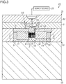
FIG. 1 is a plan view of a rotor; -
FIG. 2 is a sectional view of the rotor (sectional view taken along line II-II inFIG. 1 ); -
FIG. 3 is a sectional view illustrating a schematic configuration of a bonded-magnet injection molding device; -
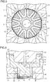
FIG. 4 is a sectional view of a magnetizing mechanism (sectional view taken along line IV-IV inFIG. 3 ); -
FIG. 5 is a schematic diagram illustrating flows of magnetic fluxes applied to a rotor core by the magnetizing mechanism; -
FIG. 6 is an enlarged sectional view of the bonded-magnet injection molding device near an injection die; -
FIG. 7 is a plan view of the injection die; and -
FIG. 8 is a schematic diagram illustrating flows of magnetic fluxes applied to the injection die by the magnetizing mechanism (sectional view taken along line VIII-VIII inFIG. 6 ). - One embodiment of a bonded-magnet injection molding device and a bonded-magnet injection molding method is described below with reference to the drawings. A
rotor 1 illustrated inFIG. 1 and FIG. 2 is rotatably disposed inside an inner periphery of a stator (not illustrated). For example, therotor 1 constitutes a motor (dynamoelectric machine) that is a drive source of an electric power steering system. - The
rotor 1 includes arotor core 12 and a plurality of bonded magnets (e.g., plastic magnets or rubber magnets) 13. Therotor core 12 is fixed to a rotating shaft 11 so as to be integrally rotatable. The bondedmagnets 13 are embedded in therotor core 12 to be fixed thereto. In other words, therotor 1 of the present embodiment is configured as what is called a magnet-embedded rotor. - Specifically, the
rotor core 12 is configured by stacking a plurality of magnetic steel sheets to form a columnar shape. Ashaft hole 14 passes through the center of therotor core 12 in the axial direction. The rotating shaft 11 is press-fitted into theshaft hole 14 such that therotor core 12 and the rotating shaft 11 are integrally rotatable. In therotor core 12, a plurality of (10 in the present embodiment)magnet insertion holes 15 are formed as hollow portions in which thebonded magnets 13 are disposed. Eachmagnet insertion hole 15 passes through therotor core 12 in the axial direction. The cross-section of eachmagnet insertion hole 15 is formed in an arc shape protruding radially inward. - Each bonded
magnet 13 is formed in a curved plate-like shape such that its cross-section has an arc shape that fits themagnet insertion hole 15. On one end surface of each bondedmagnet 13 in the axial direction, agate mark 16 is formed that is a shear mark made when agate 77 is separated after a molten bonded-magnet material is injected by an injection molding device 21 described later. In the present embodiment, eachgate mark 16 is, on one end surface of therotor core 12 in the axial direction, positioned at aspoke portion 17 formed between adjacentmagnet insertion holes 15, and is formed over radially outer end portions of the corresponding two adjacent bondedmagnets 13. The respective bondedmagnets 13 are magnetized along the thickness direction such that polarities generated at an outer periphery of therotor 1 are alternately reversed along the circumferential direction. - The following describes manufacture of the rotor, focusing on injection molding and magnetization of the
bonded magnets 13. - As illustrated in
FIG. 3 , the injection molding device 21 for thebonded magnets 13 includes alower die 22, anintermediate die 24, and anupper die 26. The lower die 22 supports therotor core 12. The intermediate die 24 includes an annularmagnetizing mechanism 23. Theupper die 26 is connected to asupply source 25 of a bonded-magnet material obtained by combining a molten resin material with a magnetic material in powder form. Thelower die 22 and theintermediate die 24 are configured as movable dies that can be integrally moved with respect to theupper die 26. - The
lower die 22 is a block-like structure made by joining together a plurality of thick metal plates. Acylindrical base portion 31 is provided on the center of an upper surface of thelower die 22. Apositioning rod 32 protrudes from the center of an upper surface of thebase portion 31. The outside diameter of thebase portion 31 is set to be substantially the same as the outside diameter of therotor core 12. Thepositioning rod 32 is formed such that its cross-sectional shape is substantially the same as the cross-sectional shape of theshaft hole 14 in therotor core 12. When thebonded magnets 13 are injection molded, thepositioning rod 32 is inserted into theshaft hole 14 in therotor core 12. This allows therotor core 12 to be placed on thebase portion 31 such that the outer peripheral surface of therotor core 12 is flush with the outer peripheral surface of thebase portion 31. - As illustrated in
FIG. 3 andFIG. 4 , the magnetizingmechanism 23 of the present embodiment is formed in an annular shape by arranging a plurality of (10 in the present embodiment) yokes 41 and a plurality of (10 in the present embodiment)permanent magnets 42 alternately in the circumferential direction. - Specifically, each
yoke 41 is made of ferromagnetic material such as iron, and is formed in a columnar shape such that its cross-section has a substantially trapezoidal shape that is long and slender. The length of eachyoke 41 along the axial direction (upper-and-lower direction inFIG. 3 ) is set longer than the axial length of therotor core 12. A magnetic-path surface 41a corresponding to a lower edge of a trapezoid formed by the cross-section of eachyoke 41 is a curved surface having an arc shape the curvature radius of which is substantially the same as that of the outer peripheral surface of therotor core 12. The respective yokes 41 are arranged at regular angular intervals in an annular shape such that the magnetic-path surfaces 41a are positioned radially inside and are in contact with the outer peripheral surface of therotor core 12 or face the outer peripheral surface of therotor core 12 with a minute clearance therebetween. - The cross-section of each columnar
permanent magnet 42 has the shape of a sector corresponding to a space betweenadjacent yokes 41. Eachpermanent magnet 42 is made by joining together magnet pieces corresponding to equal halves into which the sector formed by thepermanent magnet 42 is divided at its circumferential center. The length of eachpermanent magnet 42 along the axial direction is set longer than the axial length of therotor core 12. The inner peripheral surface of eachpermanent magnet 42 is formed in a planar shape or in a curved surface shape having a curvature radius slightly larger than that of the magnetic-path surface 41a of theyoke 41, and is positioned radially outside the magnetic-path surface 41a. The outer peripheral surface of eachpermanent magnet 42 has a curvature radius that is substantially the same as that of a side surface of eachyoke 41 positioned radially outside, and forms a smooth cylindrical surface integrally with theyoke 41. The respectivepermanent magnets 42 are arranged substantially orthogonal to contact surfaces with therotor core 12, and are magnetized alternately in the circumferential direction such that eachyoke 41 is sandwiched by the same polarities from both sides in the circumferential direction. - Thus, as illustrated in
FIG. 5 , a magnetic flux of eachpermanent magnet 42 forms a magnetic path extending from the magnetic-path surface 41a of ayoke 41, passing through the rotor core 12 (adjacent magnet insertion holes 15), and returning to the magnetic-path surface 41a of ayoke 41 disposed adjacently to theyoke 41. - As illustrated in
FIG. 3 , theintermediate die 24 includes a pair ofretainer plates 51 and acoupling member 52 disposed between theretainer plates 51. A throughhole 53 is formed in the center of eachretainer plate 51. Anaccommodating recess 54 having the shape of a circular hole is formed concentrically with the throughhole 53. The bore diameter of each throughhole 53 is set to be substantially the same as the outside diameter of thebase portion 31 of thelower die 22, and the axial length of each throughhole 53 is set shorter than the axial length of thebase portion 31 of thelower die 22. The outside diameter of theaccommodating recess 54 is set to be substantially the same as the outside diameter of the magnetizingmechanism 23. Thecoupling member 52 is formed in an annular shape such that its bore diameter is substantially the same as the outside diameter of theaccommodating recess 54. The magnetizingmechanism 23 is held using bolts (not illustrated), for example, to couple therespective retainer plates 51 to thecoupling member 52, with theaccommodating recesses 54 of therespective retainer plates 51 facing each other, an end portion of the magnetizingmechanism 23 being inserted into theaccommodating recesses 54, and thecoupling member 52 being sandwiched therebetween. - The intermediate die 24 is assembled to the
lower die 22 such that a distal end portion of thebase portion 31 is inserted inside the inner periphery of the magnetizingmechanism 23 via the throughhole 53 in one of theretainer plates 51. In a state in which theintermediate die 24 is assembled to thelower die 22 in this manner, an end portion of the magnetizingmechanism 23 on thelower die 22 side (lower side inFIG. 3 ) in the axial direction radially faces thebase portion 31, an axially central portion of the magnetizingmechanism 23 radially faces theentire rotor core 12, and an end portion of the magnetizingmechanism 23 on theupper die 26 side (upper side inFIG. 3 ) in the axial direction radially faces a protrudingportion 72 of an injection die 63 described later. - As illustrated in
FIG. 3 andFIG. 6 , theupper die 26 includes a firstupper die 61, a secondupper die 62, and the injection die (sprue bush) 63. The injection die 63 is assembled to the firstupper die 61 to inject a bonded-magnet material. The firstupper die 61 and the injection die 63 are configured to be integrally movable with respect to the secondupper die 62. - The first
upper die 61 is formed in the shape of a thick plate, and is assembled to theintermediate die 24. Afitting hole 64 passes through the firstupper die 61 in the thickness direction. The injection die 63 is fitted into thefitting hole 64. The fitting hole is 64 formed in the shape of a stepped circular hole the bore diameter of which decreases toward the intermediate die 24 (toward the lower side inFIG. 3 ). Thefitting hole 64 of the present embodiment is formed such that its cross-sectional shape on the secondupper die 62 side (upper side inFIG. 3 ) is a shape of a circle from which a part is cut off at opposite sides to have edges parallel to each other. The secondupper die 62 is formed in the shape of a thick plate. The secondupper die 62 is connected to thesupply source 25. In the secondupper die 62, a cylindricalchannel forming protrusion 65 protruding into thefitting hole 64 is formed, and also asupply channel 66 that is open at the center of an end surface of thechannel forming protrusion 65 and serves as a flow channel for a molten bonded-magnet material is formed. Thesupply channel 66 is formed in a tapered shape that linearly extends and the bore diameter of which increases toward the end surface of thechannel forming protrusion 65. - As illustrated in
FIG. 6 andFIG. 7 , the injection die 63 is made of non-magnetic material such as stainless steel. The injection die 63 has a cylindricalfitting portion 71, a cylindrical protrudingportion 72, and a plurality of (10 in the present embodiment) magnetic-flux applying members 73 as a magnetic-flux applying unit. The protrudingportion 72 is arranged concentrically with thefitting portion 71. - The
fitting portion 71 has aflange portion 71a protruding radially outward, thus forming a stepped shape such that the outer peripheral surface of thefitting portion 71 fits the inner peripheral surface of thefitting hole 64. The injection die 63 is assembled to the first and second upper dies 61 and 62, with thefitting portion 71 fitted into thefitting hole 64 from the secondupper die 62 side (upper side inFIG. 3 ) and the protrudingportion 72 protruding toward theintermediate die 24 side (lower side inFIG. 3 ). Achannel forming hole 74 is formed in thefitting portion 71 such that thechannel forming protrusion 65 is fitted into thechannel forming hole 74. In the bottom surface of thechannel forming hole 74, aflow channel recess 75 having the shape of a circular hole is formed in its center, and also a plurality of (10 in the present embodiment)flow channel grooves 76 extending radially from theflow channel recess 75 are formed. The respectiveflow channel grooves 76 are formed at regular angular intervals in the circumferential direction. In eachflow channel groove 76, agate 77 that extends in the axial direction and is open at an end surface of the protrudingportion 72 is formed at a position close to the outer periphery of the protrudingportion 72. Eachgate 77 is formed in a tapered shape that linearly extends and the bore diameter of which decreases toward the end surface of the protrudingportion 72. Thus, with thechannel forming protrusion 65 fitted into thechannel forming hole 74, flow channels of a bonded-magnet material are formed that communicate with therespective gates 77 from thesupply channel 66 through theflow channel recess 75 and the correspondingflow channel grooves 76. - The outside diameter of the protruding
portion 72 is set to be substantially the same as the outside diameter of therotor core 12, that is, the bore diameter of the throughhole 53 in eachretainer plate 51. The length of the protrudingportion 72 in the axial direction (protruding length from the first upper die 61) is set longer than the axial length of the throughhole 53 in theretainer plate 51, and thus the protrudingportion 72 is in contact with an end surface of therotor core 12 in the axial direction. Thus, the distal end portion of the protrudingportion 72 is inserted into the magnetizingmechanism 23 with theupper die 26 assembled to theintermediate die 24. The outer peripheral surface of the protrudingportion 72 is flush with the outer peripheral surface of therotor core 12. The distal end portion of the protrudingportion 72 is in contact with the magnetic-path surface 41a of eachyoke 41 or radially faces the magnetic-path surface 41a with a minute clearance therebetween. In a distal end portion on the outer peripheral surface of the protrudingportion 72, a plurality of (10 in the present embodiment) fixingholes 78 that are open in the radial direction are formed between thegates 77. Each fixinghole 78 is formed in the shape of a sector the radial depth of which is slightly greater than the radial distance from the outer peripheral surface of the protrudingportion 72 to eachgate 77. - As illustrated in
FIG. 8 , each magnetic-flux applying member 73 contains ferromagnetic material such as iron, and is formed in the shape of a sector that fits the hole shape of the corresponding fixinghole 78. Each magnetic-flux applying member 73 is fixed in the corresponding fixinghole 78 by press-fitting or welding, for example. Thus, the respective magnetic-flux applying members 73 are embedded in the protrudingportion 72 in a manner sandwiching eachgate 77 from both sides in the circumferential direction. Aside surface 73a of each magnetic-flux applying member 73 that is exposed at the outer periphery of the protrudingportion 72 radially faces the magnetic-path surface 41a of thecorresponding yoke 41. - Thus, a magnetic flux of each
permanent magnet 42 forms a magnetic path extending from the magnetic-path surface 41a of ayoke 41, entering a magnetic-flux applying member 73 of the injection die 63, passing through a magnetic-flux applying member 73 adjacent to the magnetic-flux applying member 73 via agate 77, and returning to the magnetic-path surface 41a of ayoke 41 adjacent to theyoke 41. - The following describes a method for manufacturing the rotor, focusing on injection molding and magnetization of the bonded
magnets 13 performed by the injection molding device 21. Therotor core 12 manufactured in another process is inserted into the magnetizingmechanism 23, and therotor core 12 is placed on thebase portion 31 such that thepositioning rod 32 is inserted into theshaft hole 14. Subsequently, as illustrated inFIG. 3 , thelower die 22 and theintermediate die 24 are moved to be assembled to theupper die 26. Accordingly, the protrudingportion 72 of the injection die 63 is inserted into the magnetizingmechanism 23, and the magnetic-flux applying members 73 radially face theyokes 41. In this state, the magnetic-flux applying members 73 apply magnetic fluxes into the gates 77 (seeFIG. 8 ) as described above. - A bonded-magnet material is supplied from the
supply source 25, and is injected into the magnet insertion holes 15 in therotor core 12 from thegates 77. When passing through thegates 77, the bonded-magnet material is oriented and magnetized by the magnetic fluxes passing through inside thegates 77. Subsequently, the bonded-magnet material is injected into the magnet insertion holes 15 and, also when moving inside the magnet insertion holes 15, the bonded-magnet material is gradually cured while being oriented and magnetized also by the magnetic fluxes that are generated by the magnetizingmechanism 23 and pass through the magnet insertion holes 15. The bonded-magnet material is then molded in the shapes of the magnet insertion holes 15 to form the bonded magnets 13 (seeFIG. 5 ). - After the molding of the bonded
magnet 13, thelower die 22 and theintermediate die 24 are separated from theupper die 26 such that therotor core 12 is removed. The rotating shaft 11, for example, is assembled to therotor core 12, whereby therotor 1 is manufactured. In the present embodiment, when therotor core 12 is removed, the firstupper die 61 and the secondupper die 62 are separated, and bonded magnets remaining in the flow channels and cured therein are removed together. - As described above, according to the present embodiment, the following functional effects can be obtained.
- (1) The injection die 63 is provided with the magnetic-
flux applying members 73 that apply magnetic fluxes into thegates 77, and is configured to, in injection molding of the bondedmagnets 13, inject a molten bonded-magnet material into the magnet insertion holes 15 in therotor core 12 while applying magnetic fluxes into thegate 77. Because the bonded-magnet material existing in thegates 77 before being injected into the magnet insertion holes 15 has high temperature and high flowability, the bonded magnets can be effectively magnetized by applying magnetic fluxes into the gates. This enables the bondedmagnets 13 having a high orientation rate and a high magnetization rate to be molded into therotor core 12, and thus output torque of a motor can be increased. - (2) The injection molding device 21 is provided with the magnetizing
mechanism 23 that can accommodate therotor core 12, and the magnetizingmechanism 23 is configured to apply magnetic fluxes to therotor core 12. Thus, the bonded-magnet material after being injected into the magnet insertion holes 15 in therotor core 12 can be oriented and magnetized. - (3) Each magnetic-
flux applying member 73 is made of ferromagnetic material, and theside surface 73a thereof is arranged to face the magnetic-path surface 41a of thecorresponding yoke 41 to serve as a magnetic path of magnetic fluxes of the magnetizingmechanism 23. This allows the magnetic fluxes of the magnetizingmechanism 23 to be applied into thegate 77.
During injection of a bonded-magnet material, the temperature of the injection die 63 easily becomes high due to influence of heat of the bonded-magnet material. Thus, for example, when permanent magnets are used to apply magnetic fluxes into thegates 77, the temperature of the injection die 63 and the temperature of the magnetic-flux applying member 73 become high, resulting in reduction of the magnetic fluxes applied into thegates 77. In contrast, the magnetizingmechanism 23 is not in direct contact with a molten bonded-magnet material, and thus the temperature thereof will not easily become high during injection of the bonded-magnet material when compared with the temperature of the injection die 63. Thus, magnetic fluxes generated by the magnetizingmechanism 23 are applied into thegates 77 via the magnetic-flux applying members 73, whereby reduction of the magnetic fluxes applied into thegates 77 during injection can be prevented in comparison with, for example, when permanent magnets are used. - (4) The cylindrical protruding
portion 72 is formed at an end surface of the injection die 63 in which thegates 77 are open, and the magnetic-flux applying members 73 are embedded therein such that the side surfaces 73a are exposed at the outer peripheral surface of the protrudingportion 72. The magnetizingmechanism 23 is formed in an annular shape that can accommodate, inside the inner periphery thereof, therotor core 12 and the distal end portion of the protrudingportion 72, and is arranged to face the side surfaces 73a in the radial direction. This enables the magnetic-flux applying members 73 and theyokes 41 to face each other while preventing the injection molding device 21 from upsizing. - (5) The injection die 63 is formed such that the
gates 77 are open at positions close to the outer periphery on the end surface of the protrudingportion 72. Because of this arrangement, a bonded-magnet material is injected into a range that is close to the inner peripheral surface of the magnetizingmechanism 23 and in which the magnetic field is strong, and is accordingly influenced by the strong magnetic fluxes to be magnetized. Thus, the orientation rate and the magnetization rate of the molded bondedmagnets 13 can be further increased. - (6) A plurality of bonded
magnets 13 are injection molded such that eachgate mark 16 is arranged over the bondedmagnets 13 on one end surface of therotor 1. Because of this arrangement, the bonded-magnet material is injected from onegate 77 to a plurality of magnet insertion holes 15. This eliminates the need of arranging adjacent magnet insertion holes 15 so as to be apart from each other depending on the distance betweenadjacent gates 77, and thus flexibility in designing therotor 1 can be improved. - The above-described embodiment can be implemented in the following modes in which this embodiment is appropriately modified.
- In the present embodiment, by providing a heater to the
upper die 26, the need of removing bonded magnets remaining in flow channels every time the bondedmagnets 13 are injection molded in onerotor core 12 can be eliminated. - In the present embodiment, the respective magnetic-
flux applying members 73 are embedded in the protrudingportion 72 in a manner sandwiching eachgate 77 from both sides in the circumferential direction. However, the present invention is not limited to this. For example, the respective magnetic-flux applying members 73 may be embedded in the protrudingportion 72 in a manner sandwiching eachgate 77 from both sides in the radial direction. As long as magnetic fluxes can be applied into thegates 77 from the magnetic-flux applying members 73, arrangement of the magnetic-flux applying members 73 in the injection die 63 may be changed as appropriate. Each of the magnetic-flux applying members 73 and the fixing holes 78 may be formed in a triangular shape, for example, and also the number and the shape of these may be changed as appropriate. Similarly, for example, the number and the arrangement of thegates 77 may be changed as appropriate. - In the present embodiment, the
side surface 73a of each magnetic-flux applying member 73 faces the magnetic-path surface 41a of thecorresponding yoke 41 in the radial direction. However, the present invention is not limited to this. For example, the injection die 63 may be configured such that the magnetic-flux applying members 73 are exposed at the end surface of the protrudingportion 72 and the protrudingportion 72 is larger than the bore diameter of the magnetizingmechanism 23, and each magnetic-flux applying member 73 may be arranged to face thecorresponding yoke 41 in the axial direction. - In the present embodiment, the magnetic-
flux applying members 73 containing ferromagnetic material are configured as a magnetic-flux applying unit. However, the present invention is not limited to this. For example, thepermanent magnets 42 may be configured as the magnetic-flux applying unit. In this case, the magnetic-flux applying unit does not have to face part of the magnetizingmechanism 23 to serve as a magnetic path of magnetic fluxes of the magnetizingmechanism 23.
Furthermore, an electromagnetic coil may be configured as the magnetic-flux applying unit, and the electromagnetic coil may be provided to the injection die 63. In this case, when the bondedmagnets 13 are injection molded, a molten bonded-magnet material is injected into the magnet insertion holes while electricity is supplied to the electromagnetic coil to apply magnetic fluxes into thegates 77. - In the present embodiment, the magnetizing
mechanism 23 is configured by arranging a plurality ofyokes 41 and a plurality ofpermanent magnets 42 in an annular shape. However, the present invention is not limited to this. For example, an electromagnetic coil may be used in place of thepermanent magnets 42, and the configuration thereof may be changed as appropriate. - In the present embodiment, the bonded
magnets 13 may be magnetized only by magnetic fluxes applied into thegates 77 without providing the magnetizingmechanism 23 to the injection molding device 21. - In the present embodiment, the cross-section of each
magnet insertion hole 15 has an arc shape that protrudes radially inward. However, the present invention is not limited to this. For example, the cross-section of eachmagnet insertion hole 15 may have a linear shape orthogonal to the radial direction or may have a truncated chevron shape or the like, and the shape thereof may be changed as appropriate. - In the present embodiment, the magnet insertion holes 15 only need to be open to at least one side in the axial direction.
- In the present embodiment, the injection die 63 and the
rotor core 12 are designed such that eachgate mark 16 is formed over a plurality of bonded magnets 13 (magnet insertion holes 15). However, the present invention is not limited to this. Thegate mark 16 may be formed on each single bondedmagnet 13. - In the present embodiment, the
rotor core 12 is used as a target object in which the bondedmagnets 13 are to be injection molded. However, the present invention is not limited to this. For example, the target object in which the bondedmagnets 13 are to be injection molded may be changed as appropriate to a movable element of a linear motor or a magnet sensor. - The following additionally describes technical ideas that can be understood from the present embodiment and other examples, together with the effects thereof.
- (a) In the bonded-magnet injection molding device, the gates are open at positions close to the outer periphery on the end surface of the protruding portion. By this configuration, a bonded-magnet material is injected into a range that is close to the inner peripheral surface of the magnetizing mechanism and in which the magnetic field is strong, and is accordingly influenced by the strong magnetic fluxes to be magnetized. Thus, the orientation rate and the magnetization rate of the molded bonded magnets can be satisfactorily increased.
- (b) A rotor includes: a columnar rotor core having a plurality of magnet insertion holes that are open to at least one side in the axial direction; and bonded magnets provided in the respective magnet insertion holes. On an end surface of the rotor core on an open side of the magnet insertion holes, gate marks are formed so as to be each arranged over the bonded magnets. According to the above-described configuration, each gate mark is arranged over the bonded magnets. Because of this arrangement, the bonded-magnet material is injected from one gate to a plurality of magnet insertion holes. This eliminates the need of arranging adjacent magnet insertion holes so as to be apart from each other depending on the distance between adjacent gates, for example, and thus flexibility in designing the rotor can be improved.
- According to the present invention, the magnetization rate of the bonded magnets can be increased.
Claims (6)
- A bonded-magnet injection molding device comprising:an injection die in which a gate through which a molten bonded-magnet material is injected into a hollow portion in a target object is formed, whereinthe injection die is provided with a magnetic-flux applying unit that applies a magnetic flux into the gate.
- The bonded-magnet injection molding device according to claim 1, wherein
the bonded-magnet material is injected into a magnet insertion hole in a rotor core as the hollow portion in the target object. - The bonded-magnet injection molding device according to claim 2, further comprising:
a magnetizing mechanism that applies a magnetic flux to the rotor core to magnetize the bonded-magnet material injected into the magnet insertion hole. - The bonded-magnet injection molding device according to claim 3, wherein
the magnetic-flux applying unit is made of ferromagnetic material, and faces part of the magnetizing mechanism to serve as a magnetic path of the magnetic flux of the magnetizing mechanism, thereby applying the magnetic flux of the magnetizing mechanism into the gate. - The bonded-magnet injection molding device according to claim 4, wherein
the injection die has a protruding portion at an end surface in which the gate is open,
the magnetic-flux applying unit is arranged in the protruding portion such that a side surface of the magnetic-flux applying unit is exposed at an outer peripheral surface of the protruding portion, and
the magnetizing mechanism is formed in an annular shape capable of accommodating, inside an inner periphery of the magnetizing mechanism, the rotor core and part of the protruding portion, and radially faces the side surface. - A bonded-magnet injection molding method in which a molten bonded-magnet material is injected into a hollow portion in a target object through a gate of an injection die to mold a bonded magnet, the bonded-magnet injection molding method comprising:
injecting the molten bonded-magnet material into the hollow portion while applying a magnetic flux into the gate.
Applications Claiming Priority (1)
| Application Number | Priority Date | Filing Date | Title |
|---|---|---|---|
| JP2017083663A JP6939042B2 (en) | 2017-04-20 | 2017-04-20 | Bond magnet injection molding equipment and bond magnet injection molding method |
Publications (2)
| Publication Number | Publication Date |
|---|---|
| EP3395532A1 true EP3395532A1 (en) | 2018-10-31 |
| EP3395532B1 EP3395532B1 (en) | 2020-11-18 |
Family
ID=62002089
Family Applications (1)
| Application Number | Title | Priority Date | Filing Date |
|---|---|---|---|
| EP18167505.9A Active EP3395532B1 (en) | 2017-04-20 | 2018-04-16 | Bonded-magnet injection molding device and bonded-magnet injection molding method |
Country Status (4)
| Country | Link |
|---|---|
| US (1) | US10804776B2 (en) |
| EP (1) | EP3395532B1 (en) |
| JP (1) | JP6939042B2 (en) |
| CN (1) | CN108736605B (en) |
Cited By (1)
| Publication number | Priority date | Publication date | Assignee | Title |
|---|---|---|---|---|
| WO2022049356A1 (en) * | 2020-09-07 | 2022-03-10 | Commissariat A L'energie Atomique Et Aux Energies Alternatives | Device for forming poles of a rotor |
Families Citing this family (6)
| Publication number | Priority date | Publication date | Assignee | Title |
|---|---|---|---|---|
| WO2018189822A1 (en) * | 2017-04-12 | 2018-10-18 | 三菱電機株式会社 | Ipm rotor |
| JP7099936B2 (en) * | 2018-11-15 | 2022-07-12 | 株式会社三井ハイテック | Iron core products and manufacturing methods for iron core products |
| DE102021106222A1 (en) | 2021-03-15 | 2022-09-15 | Wirthwein Ag | Bonded magnet injection molding apparatus, injection molding machine and method of manufacturing a bonded magnet injection molded part |
| CN113437843A (en) * | 2021-07-09 | 2021-09-24 | 浙江盘毂动力科技有限公司 | Rotor structure based on neodymium iron boron magnetic steel and manufacturing method |
| WO2023007706A1 (en) * | 2021-07-30 | 2023-02-02 | 川崎重工業株式会社 | Rotor, motor, and rotor manufacturing method |
| WO2023157131A1 (en) * | 2022-02-16 | 2023-08-24 | 三菱電機株式会社 | Permanent magnet rotor and method for manufacturing permanent magnet rotor |
Citations (3)
| Publication number | Priority date | Publication date | Assignee | Title |
|---|---|---|---|---|
| EP1176700A2 (en) * | 2000-07-27 | 2002-01-30 | Yamaha Hatsudoki Kabushiki Kaisha | Embedded magnet type rotor, manufacturing method and mold device |
| JP2016093091A (en) | 2014-10-30 | 2016-05-23 | 株式会社ジェイテクト | Magnet embedded rotor, and method and apparatus for manufacturing the same |
| EP3101786A1 (en) * | 2015-06-02 | 2016-12-07 | Jtekt Corporation | Manufacturing method and magnetizing device for interior permanent magnet rotor unit |
Family Cites Families (5)
| Publication number | Priority date | Publication date | Assignee | Title |
|---|---|---|---|---|
| JP6011131B2 (en) * | 2012-08-08 | 2016-10-19 | ダイキン工業株式会社 | Field element manufacturing method and injection molding apparatus |
| JP2015204638A (en) * | 2014-04-10 | 2015-11-16 | 株式会社ミツバ | Brushless motor and manufacturing method of rotor for brushless motor |
| JP2016082779A (en) * | 2014-10-20 | 2016-05-16 | 株式会社ジェイテクト | Magnet-embedded rotor unit manufacturing method and magnetization device |
| CN105576865B (en) * | 2014-10-30 | 2020-03-06 | 株式会社捷太格特 | Magnet-embedded rotor, method and apparatus for manufacturing the same |
| JP2017055491A (en) * | 2015-09-07 | 2017-03-16 | 株式会社ジェイテクト | Method for manufacturing embedded magnet type rotor unit and apparatus for manufacturing embedded magnet type rotor |
-
2017
- 2017-04-20 JP JP2017083663A patent/JP6939042B2/en active Active
-
2018
- 2018-04-12 US US15/951,513 patent/US10804776B2/en active Active
- 2018-04-16 EP EP18167505.9A patent/EP3395532B1/en active Active
- 2018-04-19 CN CN201810353629.2A patent/CN108736605B/en active Active
Patent Citations (3)
| Publication number | Priority date | Publication date | Assignee | Title |
|---|---|---|---|---|
| EP1176700A2 (en) * | 2000-07-27 | 2002-01-30 | Yamaha Hatsudoki Kabushiki Kaisha | Embedded magnet type rotor, manufacturing method and mold device |
| JP2016093091A (en) | 2014-10-30 | 2016-05-23 | 株式会社ジェイテクト | Magnet embedded rotor, and method and apparatus for manufacturing the same |
| EP3101786A1 (en) * | 2015-06-02 | 2016-12-07 | Jtekt Corporation | Manufacturing method and magnetizing device for interior permanent magnet rotor unit |
Cited By (2)
| Publication number | Priority date | Publication date | Assignee | Title |
|---|---|---|---|---|
| WO2022049356A1 (en) * | 2020-09-07 | 2022-03-10 | Commissariat A L'energie Atomique Et Aux Energies Alternatives | Device for forming poles of a rotor |
| FR3113988A1 (en) * | 2020-09-07 | 2022-03-11 | Commissariat A L'energie Atomique Et Aux Energies Alternatives | DEVICE FOR THE FORMATION OF POLES OF A ROTOR |
Also Published As
| Publication number | Publication date |
|---|---|
| CN108736605B (en) | 2022-04-19 |
| US20180309351A1 (en) | 2018-10-25 |
| JP6939042B2 (en) | 2021-09-22 |
| EP3395532B1 (en) | 2020-11-18 |
| US10804776B2 (en) | 2020-10-13 |
| CN108736605A (en) | 2018-11-02 |
| JP2018182993A (en) | 2018-11-15 |
Similar Documents
| Publication | Publication Date | Title |
|---|---|---|
| EP3395532B1 (en) | Bonded-magnet injection molding device and bonded-magnet injection molding method | |
| US5157297A (en) | Structure of radial type rotor | |
| CN109638995B (en) | Rotor for rotating electric machine and method for manufacturing same | |
| EP2897264B1 (en) | Core Manufacturing Device and Core Manufacturing Method | |
| US20160352199A1 (en) | Manufacturing method of rotor core, manufacturing method of rotor, rotor and motor | |
| US10566859B2 (en) | Rotor | |
| JP4812787B2 (en) | Method of manufacturing rotor for pump motor, pump motor, pump and rotor for pump motor | |
| WO2016147211A1 (en) | Resin filling method and resin filling device for magnet embedded core | |
| CN107852073B (en) | Rotor manufacturing method and rotor | |
| JP2016152653A (en) | Manufacturing apparatus of magnet embedded rotor and manufacturing method of magnet embedded rotor | |
| EP3732774B1 (en) | Method for manufacturing an electrical machine | |
| JP2009017712A (en) | Permanent magnet motor and manufacturing method therefor | |
| JP6076288B2 (en) | Rotor manufacturing method, rotor and motor | |
| JP5965249B2 (en) | Rotor molding method and molding die | |
| US10476359B2 (en) | Motor rotor and method for manufacturing the same | |
| EP3223409B1 (en) | Orientation magnetization device and magnet-embedded rotor | |
| JP6692870B2 (en) | Outer rotor type rotor for electric motor | |
| JP4862106B2 (en) | Manufacturing method of motor rotor | |
| CN114079336B (en) | Rotor and method for manufacturing same | |
| JP2019146303A (en) | Manufacturing device for rotor, manufacturing method of rotor, and rotor | |
| JP2017224674A (en) | Manufacturing apparatus of annular magnet and manufacturing method of annular magnet | |
| JP2017034765A (en) | Manufacturing device for magnet-inclusion type rotor | |
| JP2526141Y2 (en) | Permanent magnet rotor | |
| JP2019134566A (en) | Manufacturing method of rotor of rotary electric machine | |
| JP7224218B2 (en) | Rotor and rotor manufacturing method |
Legal Events
| Date | Code | Title | Description |
|---|---|---|---|
| PUAI | Public reference made under article 153(3) epc to a published international application that has entered the european phase |
Free format text: ORIGINAL CODE: 0009012 |
|
| STAA | Information on the status of an ep patent application or granted ep patent |
Free format text: STATUS: THE APPLICATION HAS BEEN PUBLISHED |
|
| AK | Designated contracting states |
Kind code of ref document: A1 Designated state(s): AL AT BE BG CH CY CZ DE DK EE ES FI FR GB GR HR HU IE IS IT LI LT LU LV MC MK MT NL NO PL PT RO RS SE SI SK SM TR |
|
| AX | Request for extension of the european patent |
Extension state: BA ME |
|
| STAA | Information on the status of an ep patent application or granted ep patent |
Free format text: STATUS: REQUEST FOR EXAMINATION WAS MADE |
|
| 17P | Request for examination filed |
Effective date: 20190423 |
|
| RBV | Designated contracting states (corrected) |
Designated state(s): AL AT BE BG CH CY CZ DE DK EE ES FI FR GB GR HR HU IE IS IT LI LT LU LV MC MK MT NL NO PL PT RO RS SE SI SK SM TR |
|
| STAA | Information on the status of an ep patent application or granted ep patent |
Free format text: STATUS: EXAMINATION IS IN PROGRESS |
|
| 17Q | First examination report despatched |
Effective date: 20191127 |
|
| GRAP | Despatch of communication of intention to grant a patent |
Free format text: ORIGINAL CODE: EPIDOSNIGR1 |
|
| STAA | Information on the status of an ep patent application or granted ep patent |
Free format text: STATUS: GRANT OF PATENT IS INTENDED |
|
| INTG | Intention to grant announced |
Effective date: 20200609 |
|
| GRAS | Grant fee paid |
Free format text: ORIGINAL CODE: EPIDOSNIGR3 |
|
| GRAA | (expected) grant |
Free format text: ORIGINAL CODE: 0009210 |
|
| STAA | Information on the status of an ep patent application or granted ep patent |
Free format text: STATUS: THE PATENT HAS BEEN GRANTED |
|
| AK | Designated contracting states |
Kind code of ref document: B1 Designated state(s): AL AT BE BG CH CY CZ DE DK EE ES FI FR GB GR HR HU IE IS IT LI LT LU LV MC MK MT NL NO PL PT RO RS SE SI SK SM TR |
|
| REG | Reference to a national code |
Ref country code: GB Ref legal event code: FG4D |
|
| REG | Reference to a national code |
Ref country code: CH Ref legal event code: EP |
|
| REG | Reference to a national code |
Ref country code: IE Ref legal event code: FG4D |
|
| REG | Reference to a national code |
Ref country code: DE Ref legal event code: R096 Ref document number: 602018009741 Country of ref document: DE |
|
| REG | Reference to a national code |
Ref country code: AT Ref legal event code: REF Ref document number: 1335258 Country of ref document: AT Kind code of ref document: T Effective date: 20201215 |
|
| REG | Reference to a national code |
Ref country code: AT Ref legal event code: MK05 Ref document number: 1335258 Country of ref document: AT Kind code of ref document: T Effective date: 20201118 |
|
| REG | Reference to a national code |
Ref country code: NL Ref legal event code: MP Effective date: 20201118 |
|
| PG25 | Lapsed in a contracting state [announced via postgrant information from national office to epo] |
Ref country code: FI Free format text: LAPSE BECAUSE OF FAILURE TO SUBMIT A TRANSLATION OF THE DESCRIPTION OR TO PAY THE FEE WITHIN THE PRESCRIBED TIME-LIMIT Effective date: 20201118 Ref country code: PT Free format text: LAPSE BECAUSE OF FAILURE TO SUBMIT A TRANSLATION OF THE DESCRIPTION OR TO PAY THE FEE WITHIN THE PRESCRIBED TIME-LIMIT Effective date: 20210318 Ref country code: RS Free format text: LAPSE BECAUSE OF FAILURE TO SUBMIT A TRANSLATION OF THE DESCRIPTION OR TO PAY THE FEE WITHIN THE PRESCRIBED TIME-LIMIT Effective date: 20201118 Ref country code: NO Free format text: LAPSE BECAUSE OF FAILURE TO SUBMIT A TRANSLATION OF THE DESCRIPTION OR TO PAY THE FEE WITHIN THE PRESCRIBED TIME-LIMIT Effective date: 20210218 Ref country code: GR Free format text: LAPSE BECAUSE OF FAILURE TO SUBMIT A TRANSLATION OF THE DESCRIPTION OR TO PAY THE FEE WITHIN THE PRESCRIBED TIME-LIMIT Effective date: 20210219 |
|
| PG25 | Lapsed in a contracting state [announced via postgrant information from national office to epo] |
Ref country code: AT Free format text: LAPSE BECAUSE OF FAILURE TO SUBMIT A TRANSLATION OF THE DESCRIPTION OR TO PAY THE FEE WITHIN THE PRESCRIBED TIME-LIMIT Effective date: 20201118 Ref country code: BG Free format text: LAPSE BECAUSE OF FAILURE TO SUBMIT A TRANSLATION OF THE DESCRIPTION OR TO PAY THE FEE WITHIN THE PRESCRIBED TIME-LIMIT Effective date: 20210218 Ref country code: PL Free format text: LAPSE BECAUSE OF FAILURE TO SUBMIT A TRANSLATION OF THE DESCRIPTION OR TO PAY THE FEE WITHIN THE PRESCRIBED TIME-LIMIT Effective date: 20201118 Ref country code: IS Free format text: LAPSE BECAUSE OF FAILURE TO SUBMIT A TRANSLATION OF THE DESCRIPTION OR TO PAY THE FEE WITHIN THE PRESCRIBED TIME-LIMIT Effective date: 20210318 Ref country code: LV Free format text: LAPSE BECAUSE OF FAILURE TO SUBMIT A TRANSLATION OF THE DESCRIPTION OR TO PAY THE FEE WITHIN THE PRESCRIBED TIME-LIMIT Effective date: 20201118 Ref country code: SE Free format text: LAPSE BECAUSE OF FAILURE TO SUBMIT A TRANSLATION OF THE DESCRIPTION OR TO PAY THE FEE WITHIN THE PRESCRIBED TIME-LIMIT Effective date: 20201118 |
|
| REG | Reference to a national code |
Ref country code: LT Ref legal event code: MG9D |
|
| PG25 | Lapsed in a contracting state [announced via postgrant information from national office to epo] |
Ref country code: HR Free format text: LAPSE BECAUSE OF FAILURE TO SUBMIT A TRANSLATION OF THE DESCRIPTION OR TO PAY THE FEE WITHIN THE PRESCRIBED TIME-LIMIT Effective date: 20201118 |
|
| PG25 | Lapsed in a contracting state [announced via postgrant information from national office to epo] |
Ref country code: RO Free format text: LAPSE BECAUSE OF FAILURE TO SUBMIT A TRANSLATION OF THE DESCRIPTION OR TO PAY THE FEE WITHIN THE PRESCRIBED TIME-LIMIT Effective date: 20201118 Ref country code: SK Free format text: LAPSE BECAUSE OF FAILURE TO SUBMIT A TRANSLATION OF THE DESCRIPTION OR TO PAY THE FEE WITHIN THE PRESCRIBED TIME-LIMIT Effective date: 20201118 Ref country code: LT Free format text: LAPSE BECAUSE OF FAILURE TO SUBMIT A TRANSLATION OF THE DESCRIPTION OR TO PAY THE FEE WITHIN THE PRESCRIBED TIME-LIMIT Effective date: 20201118 Ref country code: CZ Free format text: LAPSE BECAUSE OF FAILURE TO SUBMIT A TRANSLATION OF THE DESCRIPTION OR TO PAY THE FEE WITHIN THE PRESCRIBED TIME-LIMIT Effective date: 20201118 Ref country code: EE Free format text: LAPSE BECAUSE OF FAILURE TO SUBMIT A TRANSLATION OF THE DESCRIPTION OR TO PAY THE FEE WITHIN THE PRESCRIBED TIME-LIMIT Effective date: 20201118 Ref country code: SM Free format text: LAPSE BECAUSE OF FAILURE TO SUBMIT A TRANSLATION OF THE DESCRIPTION OR TO PAY THE FEE WITHIN THE PRESCRIBED TIME-LIMIT Effective date: 20201118 |
|
| REG | Reference to a national code |
Ref country code: DE Ref legal event code: R097 Ref document number: 602018009741 Country of ref document: DE |
|
| PG25 | Lapsed in a contracting state [announced via postgrant information from national office to epo] |
Ref country code: DK Free format text: LAPSE BECAUSE OF FAILURE TO SUBMIT A TRANSLATION OF THE DESCRIPTION OR TO PAY THE FEE WITHIN THE PRESCRIBED TIME-LIMIT Effective date: 20201118 |
|
| PLBE | No opposition filed within time limit |
Free format text: ORIGINAL CODE: 0009261 |
|
| STAA | Information on the status of an ep patent application or granted ep patent |
Free format text: STATUS: NO OPPOSITION FILED WITHIN TIME LIMIT |
|
| 26N | No opposition filed |
Effective date: 20210819 |
|
| PG25 | Lapsed in a contracting state [announced via postgrant information from national office to epo] |
Ref country code: IT Free format text: LAPSE BECAUSE OF FAILURE TO SUBMIT A TRANSLATION OF THE DESCRIPTION OR TO PAY THE FEE WITHIN THE PRESCRIBED TIME-LIMIT Effective date: 20201118 Ref country code: AL Free format text: LAPSE BECAUSE OF FAILURE TO SUBMIT A TRANSLATION OF THE DESCRIPTION OR TO PAY THE FEE WITHIN THE PRESCRIBED TIME-LIMIT Effective date: 20201118 Ref country code: NL Free format text: LAPSE BECAUSE OF FAILURE TO SUBMIT A TRANSLATION OF THE DESCRIPTION OR TO PAY THE FEE WITHIN THE PRESCRIBED TIME-LIMIT Effective date: 20201118 |
|
| PG25 | Lapsed in a contracting state [announced via postgrant information from national office to epo] |
Ref country code: SI Free format text: LAPSE BECAUSE OF FAILURE TO SUBMIT A TRANSLATION OF THE DESCRIPTION OR TO PAY THE FEE WITHIN THE PRESCRIBED TIME-LIMIT Effective date: 20201118 Ref country code: MC Free format text: LAPSE BECAUSE OF FAILURE TO SUBMIT A TRANSLATION OF THE DESCRIPTION OR TO PAY THE FEE WITHIN THE PRESCRIBED TIME-LIMIT Effective date: 20201118 |
|
| PG25 | Lapsed in a contracting state [announced via postgrant information from national office to epo] |
Ref country code: LU Free format text: LAPSE BECAUSE OF NON-PAYMENT OF DUE FEES Effective date: 20210416 |
|
| REG | Reference to a national code |
Ref country code: BE Ref legal event code: MM Effective date: 20210430 |
|
| PG25 | Lapsed in a contracting state [announced via postgrant information from national office to epo] |
Ref country code: ES Free format text: LAPSE BECAUSE OF FAILURE TO SUBMIT A TRANSLATION OF THE DESCRIPTION OR TO PAY THE FEE WITHIN THE PRESCRIBED TIME-LIMIT Effective date: 20201118 Ref country code: LI Free format text: LAPSE BECAUSE OF NON-PAYMENT OF DUE FEES Effective date: 20210430 Ref country code: CH Free format text: LAPSE BECAUSE OF NON-PAYMENT OF DUE FEES Effective date: 20210430 |
|
| PG25 | Lapsed in a contracting state [announced via postgrant information from national office to epo] |
Ref country code: IE Free format text: LAPSE BECAUSE OF NON-PAYMENT OF DUE FEES Effective date: 20210416 |
|
| PG25 | Lapsed in a contracting state [announced via postgrant information from national office to epo] |
Ref country code: IS Free format text: LAPSE BECAUSE OF FAILURE TO SUBMIT A TRANSLATION OF THE DESCRIPTION OR TO PAY THE FEE WITHIN THE PRESCRIBED TIME-LIMIT Effective date: 20210318 |
|
| PG25 | Lapsed in a contracting state [announced via postgrant information from national office to epo] |
Ref country code: BE Free format text: LAPSE BECAUSE OF NON-PAYMENT OF DUE FEES Effective date: 20210430 |
|
| GBPC | Gb: european patent ceased through non-payment of renewal fee |
Effective date: 20220416 |
|
| PG25 | Lapsed in a contracting state [announced via postgrant information from national office to epo] |
Ref country code: GB Free format text: LAPSE BECAUSE OF NON-PAYMENT OF DUE FEES Effective date: 20220416 |
|
| PGFP | Annual fee paid to national office [announced via postgrant information from national office to epo] |
Ref country code: FR Payment date: 20230309 Year of fee payment: 6 |
|
| PG25 | Lapsed in a contracting state [announced via postgrant information from national office to epo] |
Ref country code: CY Free format text: LAPSE BECAUSE OF FAILURE TO SUBMIT A TRANSLATION OF THE DESCRIPTION OR TO PAY THE FEE WITHIN THE PRESCRIBED TIME-LIMIT Effective date: 20201118 |
|
| PG25 | Lapsed in a contracting state [announced via postgrant information from national office to epo] |
Ref country code: HU Free format text: LAPSE BECAUSE OF FAILURE TO SUBMIT A TRANSLATION OF THE DESCRIPTION OR TO PAY THE FEE WITHIN THE PRESCRIBED TIME-LIMIT; INVALID AB INITIO Effective date: 20180416 |
|
| PGFP | Annual fee paid to national office [announced via postgrant information from national office to epo] |
Ref country code: DE Payment date: 20230228 Year of fee payment: 6 |
|
| PG25 | Lapsed in a contracting state [announced via postgrant information from national office to epo] |
Ref country code: MK Free format text: LAPSE BECAUSE OF FAILURE TO SUBMIT A TRANSLATION OF THE DESCRIPTION OR TO PAY THE FEE WITHIN THE PRESCRIBED TIME-LIMIT Effective date: 20201118 |