JP5965249B2 - Rotor molding method and molding die - Google Patents
Rotor molding method and molding die Download PDFInfo
- Publication number
- JP5965249B2 JP5965249B2 JP2012184035A JP2012184035A JP5965249B2 JP 5965249 B2 JP5965249 B2 JP 5965249B2 JP 2012184035 A JP2012184035 A JP 2012184035A JP 2012184035 A JP2012184035 A JP 2012184035A JP 5965249 B2 JP5965249 B2 JP 5965249B2
- Authority
- JP
- Japan
- Prior art keywords
- magnet
- annular
- cores
- pair
- rotor
- Prior art date
- Legal status (The legal status is an assumption and is not a legal conclusion. Google has not performed a legal analysis and makes no representation as to the accuracy of the status listed.)
- Active
Links
Images


Landscapes
- Injection Moulding Of Plastics Or The Like (AREA)
- Permanent Field Magnets Of Synchronous Machinery (AREA)
Description
本発明は、インナーロータ型モータのロータを成形する技術に関する。 The present invention relates to a technique for forming a rotor of an inner rotor type motor.
特許文献1には、射出圧力により円筒状の永久磁石が破損するのを防止するために、射出成形を行う成形金型の内径寸法を永久磁石の外径寸法より小さくし、永久磁石を成形金型に圧入することで、永久磁石がその内周側から受ける樹脂の射出圧力を成形金型により支え、更に永久磁石はそれぞれ成形金型の内周面との間の面圧力によって所要の間隔を保って保持される技術が記載されている。特許文献2には、インサート成形方法において、コレットチャック方式の成形金型を用いる技術が記載されている。特許文献3には、マグネットを2個用いたインサート成形において、スペーサを使用する技術が記載されている。
In
マグネットとして、所謂ボンド磁石のような脆性材質のものを用いる場合、射出成形時の樹脂の圧力によるマグネットの破損が問題となる。特許文献1の技術では、マグネットの外周を金型の内面で押さえ、射出成形時の樹脂の圧力にマグネットを耐えさせている。この方法は、成形金型にマグネットを圧入しなくてはならないので、成形金型内にマグネットを配置する作業時にマグネットの破損が発生する可能性がある。特許文献2のコレットチャック方式は、弾性によりマグネットの外周を押さえるので、射出成形時の樹脂の圧力にマグネットを耐えさせる点で有利であるが、成形金型にスリットが形成されているので、成形金型の内面を露出させた状態で樹脂の射出は行えない。よって、2つのリング状マグネットを軸方向で間隔をおいて配置した構造のロータの製造には利用できない。
When a brittle material such as a so-called bonded magnet is used as the magnet, damage to the magnet due to resin pressure during injection molding becomes a problem. In the technique of
このような背景において、本発明は、ロータマグネットを軸方向で離間させて2つ配置したロータを射出成形法により製造する技術において、製造時におけるマグネットの損傷を抑えることができる技術を提供することを目的とする。 In such a background, the present invention provides a technique that can suppress damage to the magnet at the time of manufacture in the technique of manufacturing the rotor in which two rotor magnets are spaced apart in the axial direction by the injection molding method. With the goal.
請求項1に記載の発明は、内径が径方向に開閉可能な一対のコアを有し、閉鎖することで略円柱状のキャビティーが形成される成形金型を用いたインナーロータ型モータ用ロータの成形方法であって、前記一対のコアを開き、前記一対のコアの内側に円環状の第1のマグネットを挿入する第1の工程と、前記一対のコアを一時的に閉じる第2の工程と、前記一対のコアの内側に円環状の第2のマグネットを挿入する第3の工程と、前記一対のコアにより前記円環状の第1のマグネットおよび前記円環状の第2のマグネットを型締めする第4の工程と、前記円環状の第1のマグネットおよび前記円環状の第2のマグネットの内側に樹脂を充填する第5の工程とを備えることを特徴とするロータの成形方法である。
The invention according to
請求項1に記載の発明では、第2の工程において、成形金型内での第1のマグネットの位置決めが行われる。そして、第4の工程において、第2のマグネットの位置決めが行われ、第1のマグネットと第2のマグネットの位置関係が決められる。請求項1に記載の発明では、開閉する一対のコアによって2つのマグネットが外側から締め付けられる。そのため、2つのマグネットの内側に樹脂を充填した際の圧力でマグネットが損傷する現象を抑えることができる。また、請求項1に記載の発明によれば、2つのマグネットを離間して配置する場合に、その位置関係を正確に決めることができる。 In the first aspect of the invention, in the second step, the first magnet is positioned in the molding die. In the fourth step, the second magnet is positioned, and the positional relationship between the first magnet and the second magnet is determined. In the first aspect of the invention, the two magnets are tightened from the outside by the pair of cores that open and close. Therefore, it is possible to suppress the phenomenon that the magnet is damaged by the pressure when the resin is filled inside the two magnets. According to the first aspect of the present invention, when the two magnets are arranged apart from each other, the positional relationship can be accurately determined.
請求項2に記載の発明は、請求項1に記載の発明において、前記一対のコアそれぞれにおける前記キャビティーに臨む面には、前記キャビティーを二分する内周方向に連続して延長する凸条が設けられており、前記凸条により、前記円環状の第1のマグネットと前記円環状の第2のマグネットの離間距離が決められることを特徴とする。請求項2に記載の発明によれば、凸条により、2つのマグネットの間隔が確保される。凸条を用いた方法は、スペーサを用いる方法に比較して、2つのマグネット間の間隔、および2つのマグネット間に形成される樹脂材料の同軸度を高く維持することができる。
According to a second aspect of the present invention, in the first aspect of the present invention, the surface of the pair of cores facing the cavities extends continuously in the inner circumferential direction that bisects the cavities. The distance between the annular first magnet and the annular second magnet is determined by the ridges. According to invention of
請求項3に記載の発明は、請求項1または2に記載の発明において、前記一対のコアにおける前記円環状の第1のマグネットおよび前記円環状の第2のマグネットの外周に対向する面には、複数の凸部が設けられ、前記複数の凸部の周囲の部分が前記第5の工程において前記円環状の第1のマグネットおよび前記円環状の第2のマグネットの内側から加わる力の逃げ部として機能することを特徴とする。
The invention according to
2つのマグネットは、樹脂の充填時に内側から圧力を受け、外側に膨張しようとする。この膨張を外側から受け止めないと、マグネットの外周が割れる(ひびが入る)が、他方において、この膨張を完全に抑え込もうとすると、マグネット内部の歪が増大し、マグネットが破損する可能性が高くなる。請求項3に記載の発明によれば、複数の凸部でマグネットの外周が複数の部分で部分的に抑えられるので、上述したマグネット表面の外側への膨張を押さえつつ、その膨張が凸部以外の領域で許容される。そして、膨張が抑えられる部分と膨張が許容される部分が分散するので、上述したメカニズムによるマグネットの破損(ひび割れも含む)が抑えられる。
The two magnets receive pressure from the inside when filled with resin and try to expand outward. If this expansion is not received from the outside, the outer periphery of the magnet will crack (crack). On the other hand, if the expansion is completely suppressed, the distortion inside the magnet may increase and the magnet may be damaged. Get higher. According to the invention of
請求項4に記載の発明は、内径が径方向に開閉可能な一対のコアを有し、閉鎖することで略円柱状のキャビティーが形成される成形金型であって、前記一対のコアそれぞれにおける前記キャビティーに臨む面には、前記キャビティーを二分する内周方向に連続して延長する凸条が設けられており、この凸条により、インサート材となる円環状の第1のマグネットと円環状の第2のマグネットの離間距離が決められることを特徴とする成形金型である。
The invention according to
請求項5に記載の発明は、請求項4に記載の発明において、前記一対のコアにおける前記円環状の第1のマグネットおよび前記円環状の第2のマグネットの外周に対向する面には、複数の凸部が設けられ、前記複数の凸部の周囲の部分が樹脂の射出時における前記円環状の第1のマグネットおよび前記円環状の第2のマグネットの内側から加わる力の逃げ部として機能することを特徴とする。
The invention according to
本発明によれば、ロータマグネットを軸方向で離間させて2つ配置したロータを射出成形法により製造する技術において、製造時におけるマグネットの損傷を抑えることができる。 ADVANTAGE OF THE INVENTION According to this invention, damage to the magnet at the time of manufacture can be suppressed in the technique which manufactures the rotor which spaced apart the rotor magnet and arrange | positioned two by the injection molding method.
(構成)
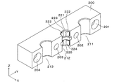
図1には、実施形態の金型の概念図(A)および(B)が示されている。図1(A)には、2分割された型を開いた状態が示され、図2(B)には、2分割された型を閉じた状態が示されている。図1には、金型100が示されている。金型100は、PM型ステッピングモータのロータ(回転子)を、樹脂を原料とする射出成形法により成形するための金型である。ここで対象となるPM型ステッピングモータは、クローポール型のステッピングモータであり、そのロータは、略円柱状の構造を有し、軸方向で間隔をおいて配置された2つの円環形状(ドーナツ形状)を有した永久磁石(ロータマグネット)を備えている。このロータは、これら2つの永久磁石をインサート材とした樹脂の射出成形により成形されている。
(Constitution)
FIG. 1 shows conceptual diagrams (A) and (B) of a mold according to an embodiment. FIG. 1A shows a state in which the two-divided mold is opened, and FIG. 2B shows a state in which the two-divided mold is closed. A
金型100は、2分割された割型となるスライドコア200および300を備えている。スライドコア200と300は、基本的に同じ構造を有している。スライドコア200と300とにより、内径が径方向に開閉可能な一対のコアを有し、閉鎖することで略円柱状のキャビティーが形成される成形金型が構成されている。図2には、スライドコア200の斜視図が示されている。スライドコア200は、組となるスライドコア300(図1参照)に対向する面に、円柱を軸方向に半割にした形状の溝211、212、213が設けられている。なお、図1に示すように、溝211に対向するスライドコア300の部分には、同様な形状の溝311が形成され、溝212に対向するスライドコア300の部分には、同様な形状の溝312が形成され、溝213に対向するスライドコア300の部分には、同様な形状の溝313が形成されている。そして、溝211と311が合わさって円柱状の空洞401が形成され、溝212と312が合わさって円柱状の空洞402が形成され、溝213と313が合わさって円柱状の空洞403が形成される。ここで、空洞401と403は、図1(B)の状態において、位置決め用のガイド材(図示省略)が貫通する孔として機能する。また、空洞402は、略円柱形状を有し、その内部に樹脂の射出が行われるキャビティーとして機能する。
The
図2に示すように、スライドコア200は、ボルト孔201,204およびガイド穴202,203を備えている。ボルト孔201,204は、後述する駆動アーム251(図1参照)にスライドコア200を固定するためのボルトを差し込むための孔である。ガイド穴202,203は、スライドコア300に取り付けられたガイドピン331,332が入る穴である。なお、スライドコア200と300は、このガイドピン331,332の有無の点で違いを有している。
As shown in FIG. 2, the
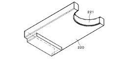
一対のスライドコア200と300それぞれにおける空洞402に臨む面には、円柱状の空洞402を軸方向で二分し、内周方向に連続して延長する凸条となる半円環状の突出部221および321が設けられている。すなわち、スライドコア200に関していうと、図2に示すスライドコア200の溝212の内面には、半円環状の突出部221が設けられている。ここで、半円環状の突出部221は、別部材であり、図3に示す入子部材220をスライドコア200に設けられた空隙(図示省略)に挿入することで、その先端が、スライドコア200から半円環状の突出部221として溝212の内面において突出する構造とされている。なお、入子部材220がスライドコア100と最初から一体物であり、溝212の内面から半円環状の突出部221が突出した構造のスライドコア200を用いることも可能である。これは、スライドコア300についても同様である。
On the surface facing the cavity 402 in each of the pair of
半円環状の突出部221は、溝212の中央(図2のZ軸方向における中央)の部分に位置している。同様に、半円環状の突出部321は、溝312の中央(図2のZ軸方向における中央)の部分に位置している。図1(B)に示すように、スライドコア200と300とを接触させ、射出成形とした状態において、半円環状の突出部221と321が合わさり、環状の突出部となる。空洞402は、この半円環状の突出部221と321とで構成される環状の突出部により、図2のZ軸の方向において中央から2分される。
The
スライドコア200の溝212の内面には、矩形形状の凸部222,224が設けられている。凸部222は、半円環状の突出部221によって上下に分割された一方(上側)の内面に3つ配置され、凸部224は、半円環状の突出部221によって上下に分割された他方(下側)の内面に3つ配置されている。凸部222,224の高さは、半円環状の突出部221の高さよりも低い。凸部222,224の周囲は、一段高さが低い凹部とされ、その部分は逃げ部223,225として機能する。凸部222,224と同様な構造は、スライドコア300の側にも設けられている。図1には、スライドコア300の溝312に設けられた凸部322が示されている。
On the inner surface of the
スライドコア200と300は、駆動系により、図1の左右の方向に動かすことが可能であり、図1(A)の型を開いた状態から図1(B)の型を閉じた状態への遷移、およびその逆の遷移が可能とされている。駆動系は、以下に述べるシリンダ機構によって構成されている。すなわち、スライドコア200には、駆動アーム251が固定され、駆動アーム251は、ピストン252に固定されている。ピストン252は、シリンダ253内で空気圧によって駆動され、シリンダ253に対して、図2の左右の方向に動く。同様に、スライドコア300には、駆動アーム351が固定され、駆動アーム351は、ピストン352に固定されている。ピストン352は、シリンダ353内で空気圧によって駆動され、シリンダ353に対して、図2の左右の方向に動く。なお、駆動源は、空気圧以外に油圧や電動であってもよい。
The
図4には、金型100で成形されるロータの側面図(A)および(C)、更に側断面図(B)が示されている。図4には、ロータ410が示されている。ロータ410は、樹脂により構成されたロータ本体411、ロータ本体に一体化されたマグネット412,413を備えている。ロータ本体411は、金型100を用いた樹脂を原料とする射出成形法により成形されている。ロータ本体411の中央(回転中心)には、回転軸となるシャフト415を貫通させるシャフト孔414が設けられている。
FIG. 4 shows a side view (A) and (C) of the rotor molded by the
マグネット412,413は、円環状の形状に成形された永久磁石である。この例では、マグネット412,413として、樹脂材料中に磁性材料を混ぜたものを成形することで構成したボンド磁石が用いられている。また、マグネット412,413は、周方向に沿って、NSNS・・と極性が交互に変わる状態で着磁されている。マグネット412と413とは、円環状の凹部416を間に挟み、特定の距離を隔てて配置されている。円環状の凹部416の外周は、マグネット412,413の部分に対して縮径された円筒面であり、その外径は、マグネット412,413の外径よりも小さい。マグネット412,413をインサート材として金型内に配置した状態で、射出成形法によりロータ本体411を成形することで、図示する一体構造が得られる。
図5(A)には、他の例のロータ420が示されている。ロータ420は、ロータ本体421の内部に金属製のスリーブ422が埋め込まれている。スリーブ422は、円筒形状を有し、その内径がシャフト孔423より少し小さい寸法に設定されている。スリーブ422を用いることで、図示しないシャフトをロータ本体421に強固に固定することができる。図5(B)には、他の例のロータ430が示されている。ロータ430がロータ420と異なるのは、スリーブ422の位置である。ロータ430では、スリーブ422が軸方向における偏った位置に配置されている。
FIG. 5A shows another example of the
(成形工程)
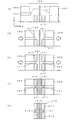
以下、図4のロータ410を得る作業の手順の一例を示す。図6には、金型100を図1のY軸正の方向(図1の上方向)に向かって見た概念図が示されている。なお、図6では、スライドコア200と300を駆動する駆動系は図示省略されている。また、図6には、シャフト孔414を形成するためのシャフト孔形成用ピン101が金型内に配置されている例が記載されている。
(Molding process)
Hereinafter, an example of an operation procedure for obtaining the
まず、スライドコア200と300を離した状態とし、スライドコア200と300の間にマグネット412(図4参照)を配置する(図6(A))。次に、スライドコア200と300を駆動係から圧力を加えることにより動かし、その間の隙間を狭める(図6(B))。この工程によって、マグネット412の位置合わせ(位置決め)が行われる。このとき半円環状の突出部221,321によって構成された円環状の突出部の縁にマグネット413を載せる。
First, the
こうして、マグネット412と413を空洞402の内部に配置した状態を得る。そして、その状態で射出成形機の型締め装置(機構)から圧力を加え、スライドコア200と300とでマグネット412と413を締め付ける(図6(C))。この際、図3に示されるスライドコア200側の凸部222,224(図3参照)、およびスライドコア300側の同様の凸部によって、マグネット412,413が周囲から押される。また、この工程において、マグネット412,413の位置合わせが行われる。
In this way, a state in which the
こうして、マグネット412,413をインサート材として、金型内に配置した状態を得、次に隙間に流動化させた樹脂材料を注入する(図6(D))。この際、マグネット412,413には、内側から圧力が加わるが、凸部222,224の周囲には、逃げ部223,225があるので、この部分にマグネット表面の変形部分が逃げ、ボンド磁石であるマグネット412,413に亀裂や破壊が生じる問題が緩和される。
Thus, the
図6(D)に示す射出成形工程が終了したら、金型から成形品を取り出し、図6(E)に示すロータ410を得る。ロータ410には、スライドコア200の側に設けられた半円環状の突出部221、およびスライドコア300の側に設けられた半円環状の突出部321がある関係で、円環状の凹部416が軸方向で隣接するマグネット412と413の間に設けられる。すなわち、マグネット412と413とが、軸方向において特定の離間距離を有した状態で離れて位置するロータの構造が得られる。
When the injection molding step shown in FIG. 6D is completed, the molded product is taken out from the mold, and the
(優位性)
スライドコア200および300は、2分割された構造であるので、半円環状の突出部221,321や凸部222,322を設けた構造を容易に得ることができる。また、半円環状の突出部221,321を用いて2つのマグネットの間隔を決める方法は、2つのマグネットの間にスペーサを挟む場合に比較して、同軸度の精度をより高く維持できる。
(Superiority)
Since the
2つのマグネットの外周が2つのスライドコアによって軸中心に向かって押さえつけられるので、樹脂の射出圧力によるマグネットの破損を抑えることができる。加えて、凸部222,322の周囲を、樹脂の射出圧力により変形するマグネットの逃げ部として機能させることもマグネットの破損を抑える上で有効に機能する。このマグネットの破損が抑えられる機能は、ボンド磁石のような脆弱なマグネットを用いる場合に特に有効となる。
Since the outer circumferences of the two magnets are pressed toward the center of the shaft by the two slide cores, it is possible to suppress breakage of the magnet due to the injection pressure of the resin. In addition, allowing the periphery of the
また、スライドコア200と300の寸法精度によって、2つのマグネットの位置精度が決まるので、インサート成形時におけるマグネットの位置決め精度を高く維持することができる。また、スライドコア200と300の駆動系を調整することで、型締め時においてマグネットにかかる圧力を容易に調整できる。また型締め時においてマグネットに加わる圧力は、凸部222,322の高さを設定することで調整することもできる。また、2つのマグネット間における樹脂部の外径がマグネットの外径より小さいので、モータ組み付け後において、駆動時にロータの一部がステータに当たるなどの問題が発生しない。
Further, since the positional accuracy of the two magnets is determined by the dimensional accuracy of the
(その他)
凸部222,223の形状は矩形に限定されず、円形形状、楕円形状、四角以外の多角形状であってもよい。またその数も図2に例示する数に限定されない。図6(C)の状態において、シャフト415を金型内にインサート材として配置すると、射出成形時にロータ410にシャフト415を一体化させることができる。また、スリーブ422を金型内にインサート材として配置した状態で射出成形を行うことで、図5(A)や(B)に示す構造を得ることができる。
(Other)
The shape of the
本発明の態様は、上述した個々の実施形態に限定されるものではなく、当業者が想到しうる種々の変形も含むものであり、本発明の効果も上述した内容に限定されない。すなわち、特許請求の範囲に規定された内容およびその均等物から導き出される本発明の概念的な思想と趣旨を逸脱しない範囲で種々の追加、変更および部分的削除が可能である。 The aspect of the present invention is not limited to the individual embodiments described above, and includes various modifications that can be conceived by those skilled in the art, and the effects of the present invention are not limited to the contents described above. That is, various additions, modifications, and partial deletions can be made without departing from the concept and spirit of the present invention derived from the contents defined in the claims and equivalents thereof.
本発明は、インナーロータ型モータのロータの製造技術に利用することができる。 INDUSTRIAL APPLICABILITY The present invention can be used for a rotor manufacturing technique for an inner rotor type motor.
100…金型、101…シャフト孔形成用ピン、200…スライドコア、201…ボルト穴、202…ガイド穴、203…ガイド穴、204…ボルト穴、211…溝、212…溝、213…溝、220…入子部材、221…半円環状の突出部、222…凸部、223…逃げ部、224…凸部、225…逃げ部、251…駆動アーム、252…ピストン、253…シリンダ、300…スライドコア、311…溝、312…溝、313…溝、321…半円環状の突出部、322…凸部、331…ガイドピン、332…ガイドピン、351…駆動アーム、352…ピストン、353…シリンダ、401…空洞、402…空洞(樹脂が充填されるキャビティー)、403…空洞、410…ロータ、411…ロータ本体、412…マグネット、413…マグネット、414…シャフト孔、415…シャフト、416…円環状の凹部、420…ロータ、421…ロータ本体、422…スリーブ、423…シャフト孔、430…ロータ。
DESCRIPTION OF
Claims (5)
前記一対のコアを開き、前記一対のコアの内側に円環状の第1のマグネットを挿入する第1の工程と、
前記一対のコアを一時的に閉じる第2の工程と、
前記一対のコアの内側に円環状の第2のマグネットを挿入する第3の工程と、
前記一対のコアにより前記円環状の第1のマグネットおよび前記円環状の第2のマグネットを型締めする第4の工程と、
前記円環状の第1のマグネットおよび前記円環状の第2のマグネットの内側に樹脂を充填する第5の工程と
を備えることを特徴とするロータの成形方法。 A method of forming a rotor for an inner rotor type motor using a molding die having a pair of cores whose inner diameters can be opened and closed in a radial direction, and forming a substantially cylindrical cavity by closing,
A first step of opening the pair of cores and inserting an annular first magnet inside the pair of cores;
A second step of temporarily closing the pair of cores;
A third step of inserting an annular second magnet inside the pair of cores;
A fourth step of clamping the annular first magnet and the annular second magnet by the pair of cores;
And a fifth step of filling a resin inside the annular first magnet and the annular second magnet.
前記凸条により、前記円環状の第1のマグネットと前記円環状の第2のマグネットの離間距離が決められることを特徴とする請求項1に記載のロータの成形方法。 The surface facing the cavity in each of the pair of cores is provided with ridges extending continuously in the inner circumferential direction that bisects the cavity,
2. The rotor forming method according to claim 1, wherein a distance between the annular first magnet and the annular second magnet is determined by the protrusions.
前記一対のコアそれぞれにおける前記キャビティーに臨む面には、前記キャビティーを二分する内周方向に連続して延長する凸条が設けられており、
この凸条により、インサート材となる円環状の第1のマグネットと円環状の第2のマグネットの離間距離が決められることを特徴とする成形金型。 A molding die having a pair of cores whose inner diameter can be opened and closed in the radial direction, and forming a substantially cylindrical cavity by closing,
The surface facing the cavity in each of the pair of cores is provided with ridges extending continuously in the inner circumferential direction that bisects the cavity,
A molding die characterized in that a separation distance between an annular first magnet and an annular second magnet serving as an insert material is determined by the protrusions.
Priority Applications (1)
| Application Number | Priority Date | Filing Date | Title |
|---|---|---|---|
| JP2012184035A JP5965249B2 (en) | 2012-08-23 | 2012-08-23 | Rotor molding method and molding die |
Applications Claiming Priority (1)
| Application Number | Priority Date | Filing Date | Title |
|---|---|---|---|
| JP2012184035A JP5965249B2 (en) | 2012-08-23 | 2012-08-23 | Rotor molding method and molding die |
Publications (2)
| Publication Number | Publication Date |
|---|---|
| JP2014040063A JP2014040063A (en) | 2014-03-06 |
| JP5965249B2 true JP5965249B2 (en) | 2016-08-03 |
Family
ID=50392758
Family Applications (1)
| Application Number | Title | Priority Date | Filing Date |
|---|---|---|---|
| JP2012184035A Active JP5965249B2 (en) | 2012-08-23 | 2012-08-23 | Rotor molding method and molding die |
Country Status (1)
| Country | Link |
|---|---|
| JP (1) | JP5965249B2 (en) |
Families Citing this family (5)
| Publication number | Priority date | Publication date | Assignee | Title |
|---|---|---|---|---|
| JP6700575B2 (en) | 2015-09-25 | 2020-05-27 | 株式会社リコー | Circuit device, photodetector, object detection device, sensing device, mobile device, photodetection method, and object detection method |
| JP2019181839A (en) * | 2018-04-12 | 2019-10-24 | 株式会社ケーヒン | Manufacturing mold device of rotor for brushless motor |
| CN108943568A (en) * | 2018-07-30 | 2018-12-07 | 洽兴包装工业(中国)有限公司 | Magnetic part assembles equipment |
| CN109225757B (en) * | 2018-10-15 | 2019-12-31 | 中南大学 | Magnetic suction clamping type photoelectric detector automatic coupling dispensing curing system and method |
| CN110434294B (en) * | 2019-09-10 | 2024-02-27 | 天津鹏翎集团股份有限公司 | Mould and joint |
Family Cites Families (4)
| Publication number | Priority date | Publication date | Assignee | Title |
|---|---|---|---|---|
| JPS5445717A (en) * | 1977-09-19 | 1979-04-11 | Omron Tateisi Electronics Co | Preparing magnetic rotor |
| JPH0318252A (en) * | 1989-06-15 | 1991-01-25 | Furukawa Electric Co Ltd:The | Integrally forming method for magnet |
| JP2723659B2 (en) * | 1990-07-11 | 1998-03-09 | 株式会社三協精機製作所 | Method for manufacturing rotor of small motor |
| JP2001246645A (en) * | 2000-03-06 | 2001-09-11 | Canon Electronics Inc | Mold for manufacturing magnet rotor |
-
2012
- 2012-08-23 JP JP2012184035A patent/JP5965249B2/en active Active
Also Published As
| Publication number | Publication date |
|---|---|
| JP2014040063A (en) | 2014-03-06 |
Similar Documents
| Publication | Publication Date | Title |
|---|---|---|
| US10530227B2 (en) | Manufacturing method of rotor core, manufacturing method of rotor, rotor and motor | |
| JP5965249B2 (en) | Rotor molding method and molding die | |
| KR101221135B1 (en) | Rotor for motor | |
| JP6325272B2 (en) | Resin casing molding method and motor | |
| CN108736605B (en) | Bonded magnet injection molding device and bonded magnet injection molding method | |
| KR101730898B1 (en) | Rotor unit, rotating electrical machine, and method for manufacturing rotor unit | |
| CN111245123B (en) | Method for manufacturing rotor magnet, and permanent magnet motor | |
| JP6221037B2 (en) | Method for molding motor and resin casing | |
| JP6153826B2 (en) | Rotor with permanent magnet and manufacturing method thereof | |
| JP2017005854A (en) | Rotor, motor, and manufacturing method of rotor | |
| JP5535827B2 (en) | Method for manufacturing a Halbach array magnet | |
| JP2006223076A (en) | Outer rotor and its manufacturing method | |
| US10476359B2 (en) | Motor rotor and method for manufacturing the same | |
| JP2019134566A (en) | Manufacturing method of rotor of rotary electric machine | |
| JP2018501774A (en) | Motor rotor | |
| JP2015192573A (en) | Rotor manufacturing method, rotor, and motor | |
| JP2006187176A (en) | Manufacturing method of outer rotor | |
| KR101247685B1 (en) | Rotor, motor having the rotor and rotor manufacturing method | |
| JP5949178B2 (en) | Yoke assembly for torque detection device and manufacturing method thereof | |
| JP7363296B2 (en) | Holder, rotor, motor, and rotor manufacturing method | |
| KR101593066B1 (en) | Metallic mold and injection molding machine with metallic mold | |
| KR20140137266A (en) | Mold for manufacturing rotor, fixing jig for fabricating the mold and method of manufacturing the mold | |
| JP2019146303A (en) | Manufacturing device for rotor, manufacturing method of rotor, and rotor | |
| JP5949320B2 (en) | Yoke assembly for torque detection device and manufacturing method thereof | |
| JP6079751B2 (en) | Rotor manufacturing method |
Legal Events
| Date | Code | Title | Description |
|---|---|---|---|
| A621 | Written request for application examination |
Free format text: JAPANESE INTERMEDIATE CODE: A621 Effective date: 20150706 |
|
| A977 | Report on retrieval |
Free format text: JAPANESE INTERMEDIATE CODE: A971007 Effective date: 20160317 |
|
| A131 | Notification of reasons for refusal |
Free format text: JAPANESE INTERMEDIATE CODE: A131 Effective date: 20160324 |
|
| A521 | Written amendment |
Free format text: JAPANESE INTERMEDIATE CODE: A523 Effective date: 20160519 |
|
| TRDD | Decision of grant or rejection written | ||
| A01 | Written decision to grant a patent or to grant a registration (utility model) |
Free format text: JAPANESE INTERMEDIATE CODE: A01 Effective date: 20160621 |
|
| A61 | First payment of annual fees (during grant procedure) |
Free format text: JAPANESE INTERMEDIATE CODE: A61 Effective date: 20160701 |
|
| R150 | Certificate of patent or registration of utility model |
Ref document number: 5965249 Country of ref document: JP Free format text: JAPANESE INTERMEDIATE CODE: R150 |
|
| R250 | Receipt of annual fees |
Free format text: JAPANESE INTERMEDIATE CODE: R250 |
|
| S533 | Written request for registration of change of name |
Free format text: JAPANESE INTERMEDIATE CODE: R313533 |
|
| R350 | Written notification of registration of transfer |
Free format text: JAPANESE INTERMEDIATE CODE: R350 |
|
| R250 | Receipt of annual fees |
Free format text: JAPANESE INTERMEDIATE CODE: R250 |