JP6206438B2 - Laminated rotor and manufacturing method thereof - Google Patents
Laminated rotor and manufacturing method thereof Download PDFInfo
- Publication number
- JP6206438B2 JP6206438B2 JP2015075440A JP2015075440A JP6206438B2 JP 6206438 B2 JP6206438 B2 JP 6206438B2 JP 2015075440 A JP2015075440 A JP 2015075440A JP 2015075440 A JP2015075440 A JP 2015075440A JP 6206438 B2 JP6206438 B2 JP 6206438B2
- Authority
- JP
- Japan
- Prior art keywords
- laminated steel
- bridge member
- hole
- laminated
- plate
- Prior art date
- Legal status (The legal status is an assumption and is not a legal conclusion. Google has not performed a legal analysis and makes no representation as to the accuracy of the status listed.)
- Active
Links
Images


Classifications
-
- H—ELECTRICITY
- H02—GENERATION; CONVERSION OR DISTRIBUTION OF ELECTRIC POWER
- H02K—DYNAMO-ELECTRIC MACHINES
- H02K1/00—Details of the magnetic circuit
- H02K1/06—Details of the magnetic circuit characterised by the shape, form or construction
- H02K1/22—Rotating parts of the magnetic circuit
- H02K1/27—Rotor cores with permanent magnets
- H02K1/2706—Inner rotors
- H02K1/272—Inner rotors the magnetisation axis of the magnets being perpendicular to the rotor axis
- H02K1/274—Inner rotors the magnetisation axis of the magnets being perpendicular to the rotor axis the rotor consisting of two or more circumferentially positioned magnets
- H02K1/2753—Inner rotors the magnetisation axis of the magnets being perpendicular to the rotor axis the rotor consisting of two or more circumferentially positioned magnets the rotor consisting of magnets or groups of magnets arranged with alternating polarity
- H02K1/276—Magnets embedded in the magnetic core, e.g. interior permanent magnets [IPM]
- H02K1/2766—Magnets embedded in the magnetic core, e.g. interior permanent magnets [IPM] having a flux concentration effect
- H02K1/2773—Magnets embedded in the magnetic core, e.g. interior permanent magnets [IPM] having a flux concentration effect consisting of tangentially magnetized radial magnets
-
- H—ELECTRICITY
- H02—GENERATION; CONVERSION OR DISTRIBUTION OF ELECTRIC POWER
- H02K—DYNAMO-ELECTRIC MACHINES
- H02K1/00—Details of the magnetic circuit
- H02K1/06—Details of the magnetic circuit characterised by the shape, form or construction
- H02K1/22—Rotating parts of the magnetic circuit
- H02K1/27—Rotor cores with permanent magnets
- H02K1/2706—Inner rotors
- H02K1/272—Inner rotors the magnetisation axis of the magnets being perpendicular to the rotor axis
- H02K1/274—Inner rotors the magnetisation axis of the magnets being perpendicular to the rotor axis the rotor consisting of two or more circumferentially positioned magnets
- H02K1/2753—Inner rotors the magnetisation axis of the magnets being perpendicular to the rotor axis the rotor consisting of two or more circumferentially positioned magnets the rotor consisting of magnets or groups of magnets arranged with alternating polarity
- H02K1/276—Magnets embedded in the magnetic core, e.g. interior permanent magnets [IPM]
- H02K1/2766—Magnets embedded in the magnetic core, e.g. interior permanent magnets [IPM] having a flux concentration effect
-
- H—ELECTRICITY
- H02—GENERATION; CONVERSION OR DISTRIBUTION OF ELECTRIC POWER
- H02K—DYNAMO-ELECTRIC MACHINES
- H02K15/00—Methods or apparatus specially adapted for manufacturing, assembling, maintaining or repairing of dynamo-electric machines
- H02K15/02—Methods or apparatus specially adapted for manufacturing, assembling, maintaining or repairing of dynamo-electric machines of stator or rotor bodies
- H02K15/03—Methods or apparatus specially adapted for manufacturing, assembling, maintaining or repairing of dynamo-electric machines of stator or rotor bodies having permanent magnets
-
- H—ELECTRICITY
- H02—GENERATION; CONVERSION OR DISTRIBUTION OF ELECTRIC POWER
- H02K—DYNAMO-ELECTRIC MACHINES
- H02K15/00—Methods or apparatus specially adapted for manufacturing, assembling, maintaining or repairing of dynamo-electric machines
- H02K15/12—Impregnating, heating or drying of windings, stators, rotors or machines
Description
本発明は、積層型ロータ及びその製造方法に関し、特に永久磁石が樹脂封止された積層型ロータの製造方法に関する。 The present invention relates to a laminated rotor and a manufacturing method thereof, and more particularly to a manufacturing method of a laminated rotor in which a permanent magnet is resin-sealed.
積層鋼板に永久磁石が挿入された積層型ロータは、例えばハイブリッド自動車等の電動モータに用いられている。このような積層型ロータは、特許文献1に開示されているように、積層鋼板に設けられた磁石孔に永久磁石を挿入した後、磁石孔と永久磁石との間隙に溶融樹脂を充填することにより、製造されている。
A laminated rotor in which a permanent magnet is inserted into a laminated steel sheet is used for an electric motor such as a hybrid vehicle. In such a laminated rotor, as disclosed in
ところで、積層型ロータの構造として図15、図16のようなものが考えられる。図15は、図16に示した積層型ロータの部分水平断面図におけるXV−XV垂直断面図であって、積層型ロータの製造方法を示している。図15、図16に示すように、この積層型ロータでは、永久磁石22aを挿入するための磁石孔12aに加え、磁束漏れ抑制孔14が、積層鋼板10に設けられている。そして、磁束漏れ抑制孔14には補強用の非磁性のブリッジ部材40が複数並設されている。図16に示すように、ブリッジ部材40は、磁束漏れ抑制孔14を跨ぐように、積層鋼板10に挿入され固定されている。ブリッジ部材40の水平断面形状は、図16に示されるように例えばI字状(すなわち幅方向両端がT字状)とされる。
By the way, as the structure of the laminated rotor, the ones shown in FIGS. 15 and 16 can be considered. 15 is an XV-XV vertical cross-sectional view in the partial horizontal cross-sectional view of the laminated rotor shown in FIG. 16, showing a method for manufacturing the laminated rotor. As shown in FIGS. 15 and 16, in this laminated rotor, the magnetic flux
図15に示すように、積層型ロータを製造する際、ブリッジ部材40が挿入された積層鋼板10を下型70上に載置し、磁石孔12aに永久磁石22aを挿入した後、上型60を降下させる。そして、プランジャ80によって溶融樹脂30を押し出し、磁石孔12aと永久磁石22aとの間隙に樹脂層32aを形成する。これにより、永久磁石22aが樹脂封止される。
As shown in FIG. 15, when manufacturing the laminated rotor, the laminated
図16に示すように、磁石孔12aと磁束漏れ抑制孔14とは連通しているが、図15に示すように、左端のブリッジ部材40により仕切られている。すなわち、磁石孔12aに充填された溶融樹脂30が、左端のブリッジ部材40によって堰き止められ、磁束漏れ抑制孔14に流れ込まない構造になっている。そのため、ブリッジ部材40の設計上の長さ寸法(図15におけるz軸方向の寸法)は、積層鋼板10の積層厚さ寸法と同じとされる。しかしながら、積層鋼板10の積層厚さ寸法とブリッジ部材40の長さ寸法とが、いずれも許容寸法公差内であっても、両者の差が大きくなると(例えば一方が最大許容寸法となり他方が最小許容寸法となったような場合)、磁束漏れ抑制孔14に溶融樹脂30が流れ込んでしまう場合があった。
As shown in FIG. 16, the
具体的には、図15の例のように、積層鋼板10の積層厚さ寸法よりもブリッジ部材40の長さ寸法が小さい場合、上型60の型面とブリッジ部材40の上端面との間に隙間ができる。そのため、溶融樹脂30は、左端のブリッジ部材40の上端を乗り越え、磁束漏れ抑制孔14に流れ込む。逆に、積層鋼板10の積層厚さ寸法よりもブリッジ部材40の長さ寸法が大きい場合には、上型60の型面は、積層鋼板10の上端面から突出するブリッジ部材40と当たることになる。そのため、積層鋼板10の上端面と上型60の型面との間に隙間ができ、図16に矢印で示されるように、左端のブリッジ部材40の周りから磁束漏れ抑制孔14に溶融樹脂30が流れ込む。磁束漏れ抑制孔14へのこのような樹脂の流れ込み自体は、樹脂材料の浪費ではあるものの、電動モータの性能を減じることにはならない。しかしながら、流れ込んで硬化した樹脂片が積層型ロータの回転によって飛散すると、電動モータの不具合に繋がり得る。そのため、磁束漏れ抑制孔14への樹脂の流れ込みは、製品品質の観点からも抑制することが望ましい。
なお、図15及び図16は、あくまでも課題の発生メカニズムを例示したものであり、本発明が図15、図16に示した構成によって限定されるものではない。例えば、磁石孔12aと磁束漏れ抑制孔14とは連通していなくても、磁束漏れ抑制孔14への樹脂の流れ込みは起こり得る。
Specifically, as shown in the example of FIG. 15, when the length dimension of the
15 and 16 merely illustrate the generation mechanism of the problem, and the present invention is not limited to the configuration shown in FIGS. 15 and 16. For example, even if the
本発明は、上記に鑑みなされたものであって、磁束漏れ抑制孔への樹脂の流れ込みを抑制可能な積層型ロータ及びその製造方法を提供するものである。 This invention is made | formed in view of the above, Comprising: The laminated type rotor which can suppress the inflow of the resin to a magnetic flux leak suppression hole, and its manufacturing method are provided.
本発明の一態様に係る積層型ロータの製造方法は、
磁石孔と、磁束漏れを抑制するための磁束漏れ抑制孔とが形成された積層鋼板と、
前記磁石孔に挿入された磁石体と、
前記磁束漏れ抑制孔を跨ぐように前記積層鋼板に挿入された非磁性のブリッジ部材と、を備えた積層型ロータの製造方法であって、
前記積層鋼板の厚さ寸法よりも大きい長さ寸法を有する前記ブリッジ部材を前記磁束漏れ抑制孔に挿入し、前記ブリッジ部材の先端部を前記積層鋼板の端面から突出させる工程と、
前記積層鋼板の端面から突出した前記ブリッジ部材の先端部を収容する収容部が形成された型部材の型面を前記積層鋼板の端面に圧接し、前記磁石孔の開口部を塞いだ状態で、前記磁石孔と前記磁石体との隙間に溶融樹脂を充填する工程と、を備えるものである。
A method for manufacturing a laminated rotor according to an aspect of the present invention includes:
Laminated steel sheet in which a magnet hole and a magnetic flux leakage suppression hole for suppressing magnetic flux leakage are formed,
A magnet body inserted into the magnet hole;
A non-magnetic bridge member inserted into the laminated steel sheet so as to straddle the magnetic flux leakage suppression hole, and a manufacturing method of a laminated rotor comprising:
Inserting the bridge member having a length dimension greater than the thickness dimension of the laminated steel sheet into the magnetic flux leakage suppression hole, and projecting the end of the bridge member from the end face of the laminated steel sheet;
In a state where the mold surface of the mold member in which the housing portion that accommodates the distal end portion of the bridge member protruding from the end surface of the laminated steel plate is pressed against the end surface of the laminated steel plate and the opening of the magnet hole is blocked, Filling a gap between the magnet hole and the magnet body with a molten resin.
本発明の一態様に係る積層型ロータの製造方法では、積層鋼板の厚さ寸法よりも大きい長さ寸法を有するブリッジ部材を磁束漏れ抑制孔に挿入し、積層鋼板の端面からブリッジ部材の先端部を突出させておく。その後、積層鋼板の端面から突出したブリッジ部材の先端部を収容する収容部が形成された型部材の型面を、前記積層鋼板の端面に圧接し、前記磁石孔の開口部を塞いだ状態で、前記磁石孔と前記磁石体との隙間に溶融樹脂を充填する。このような構成により、ブリッジ部材の長さ寸法及び積層鋼板の厚さ寸法の誤差が大きくなっても、磁石孔の開口部を塞いだ状態で樹脂を充填することができる。従って、磁束漏れ抑制孔への樹脂の流れ込みを抑制することができる。 In the method for manufacturing a laminated rotor according to one aspect of the present invention, a bridge member having a length dimension larger than the thickness dimension of the laminated steel sheet is inserted into the magnetic flux leakage suppression hole, and the end portion of the bridge member from the end face of the laminated steel sheet Keep protruding. After that, in a state where the mold surface of the mold member in which the housing portion that accommodates the tip portion of the bridge member protruding from the end surface of the laminated steel plate is pressed against the end surface of the laminated steel plate and the opening of the magnet hole is blocked The molten resin is filled in the gap between the magnet hole and the magnet body. With such a configuration, even when errors in the length dimension of the bridge member and the thickness dimension of the laminated steel sheet increase, the resin can be filled in a state where the opening of the magnet hole is closed. Therefore, the resin can be prevented from flowing into the magnetic flux leakage suppression hole.
非磁性のプレートを前記積層鋼板の端面に被せ、前記プレートに設けられたスリットに前記ブリッジ部材の先端部を圧入して突出させる工程をさらに備え、前記プレートにより前記磁石孔の開口部を塞いだ状態で、前記磁石孔と前記磁石体との隙間に溶融樹脂を充填することが好ましい。より確実に磁束漏れ抑制孔への樹脂の流れ込みを抑制することができる。
また、前記プレートに前記磁石体を押さえるための突起を設けることが好ましい。所定の位置に磁石体を固定した状態で、磁石体を樹脂封止することができる。
A step of covering the end surface of the laminated steel plate with a non-magnetic plate, and further pressing the tip of the bridge member into a slit provided in the plate to protrude, and the opening of the magnet hole was closed with the plate In the state, it is preferable to fill the gap between the magnet hole and the magnet body with molten resin. The flow of resin into the magnetic flux leakage suppression hole can be suppressed more reliably.
Moreover, it is preferable to provide a projection for pressing the magnet body on the plate. With the magnet body fixed at a predetermined position, the magnet body can be resin-sealed.
本発明の一態様に係る積層型ロータは、
磁石孔と、前記磁石孔と連通する磁束漏れ抑制孔とを有する積層鋼板と、
前記磁石孔に挿入され、樹脂封止された磁石体と、
前記磁束漏れ抑制孔を跨ぐように、前記積層鋼板に挿入された非磁性のブリッジ部材と、を備えた積層型ロータであって、
前記ブリッジ部材の長さ寸法は、前記積層鋼板の厚さ寸法よりも大きく、先端部が前記積層鋼板の端面から突出しているとともに、
前記積層鋼板の前記端面に被せられ、かつ、前記ブリッジ部材の先端部を突出させるスリットを有する非磁性のプレートをさらに備えるものである。
The laminated rotor according to one aspect of the present invention is
A laminated steel sheet having a magnet hole and a magnetic flux leakage suppression hole communicating with the magnet hole;
A magnet body inserted into the magnet hole and sealed with resin;
A non-magnetic bridge member inserted into the laminated steel sheet so as to straddle the magnetic flux leakage suppression hole, and a laminated rotor comprising:
The length dimension of the bridge member is larger than the thickness dimension of the laminated steel sheet, and the tip protrudes from the end surface of the laminated steel sheet.
It further includes a nonmagnetic plate that covers the end face of the laminated steel plate and has a slit that projects the tip of the bridge member.
本発明の一態様に係る積層型ロータでは、ブリッジ部材の長さ寸法が、積層鋼板の厚さ寸法よりも大きく、先端部が積層鋼板の端面から突出している。そして、ブリッジ部材の先端部を突出させるスリットを有する非磁性のプレートが、積層鋼板の端面に被せられている。このような構成により、ブリッジ部材の長さ寸法及び積層鋼板の厚さ寸法の誤差が大きくなっても、磁石孔の開口部を塞いだ状態で樹脂を充填することができる。従って、磁束漏れ抑制孔への樹脂の流れ込みを抑制することができる。 In the laminated rotor according to one aspect of the present invention, the length dimension of the bridge member is larger than the thickness dimension of the laminated steel sheet, and the tip portion protrudes from the end surface of the laminated steel sheet. And the nonmagnetic plate which has the slit which makes the front-end | tip part of a bridge member protrude is covered on the end surface of a laminated steel plate. With such a configuration, even when errors in the length dimension of the bridge member and the thickness dimension of the laminated steel sheet increase, the resin can be filled in a state where the opening of the magnet hole is closed. Therefore, the resin can be prevented from flowing into the magnetic flux leakage suppression hole.
前記プレートが前記磁石体を押さえるための突起を有することが好ましい。所定の位置に磁石体を固定した状態で、磁石体を樹脂封止することができる。 It is preferable that the plate has a protrusion for pressing the magnet body. With the magnet body fixed at a predetermined position, the magnet body can be resin-sealed.
本発明により、磁束漏れ抑制孔への樹脂の流れ込みを抑制可能な積層型ロータ及びその製造方法を提供することができる。 ADVANTAGE OF THE INVENTION By this invention, the lamination type rotor which can suppress the inflow of the resin to a magnetic flux leak suppression hole, and its manufacturing method can be provided.
以下、本発明を適用した具体的な実施形態について、図面を参照しながら詳細に説明する。ただし、本発明が以下の実施形態に限定される訳ではない。また、説明を明確にするため、以下の記載及び図面は、適宜、簡略化されている。 Hereinafter, specific embodiments to which the present invention is applied will be described in detail with reference to the drawings. However, the present invention is not limited to the following embodiments. In addition, for clarity of explanation, the following description and drawings are simplified as appropriate.
(第1の実施形態)
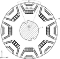
図1〜図5を参照して、第1の実施形態に係る積層型ロータについて説明する。図1は、第1の実施形態に係る積層型ロータの水平断面図である。図2は、第1の実施形態に係る積層型ロータの部分水平断面図である。図3は、図2における積層鋼板10のみを示した図である。図4は、第1の実施形態に係る積層型ロータの部分平面図である。図5は、図2、図4におけるV−V垂直断面図である。
(First embodiment)
The laminated rotor according to the first embodiment will be described with reference to FIGS. FIG. 1 is a horizontal cross-sectional view of the laminated rotor according to the first embodiment. FIG. 2 is a partial horizontal cross-sectional view of the laminated rotor according to the first embodiment. FIG. 3 shows only the
なお、図面に示した右手系xyz座標は、図面間において相互に対応しているが、構成要素の位置関係を説明するための便宜的なものである。通常、xy平面が水平面を構成し、z軸プラス向きが鉛直上向きとなる。 Note that the right-handed xyz coordinates shown in the drawings correspond to each other in the drawings, but are for convenience in explaining the positional relationship of the components. Usually, the xy plane constitutes a horizontal plane, and the z-axis plus direction is vertically upward.
図1に示すように、本実施形態に係る積層型ロータは、回転軸1、積層鋼板10、永久磁石(磁石体)21、22a、22bを備えている。さらに、本実施形態に係る積層型ロータは、図2などに示すブリッジ部材40、図4などに示すプレート50を備えている。なお、理解し易いように、図1では、積層鋼板10には斜線を付していない。
As shown in FIG. 1, the laminated rotor according to the present embodiment includes a
<積層型ロータの構成>
まず、図1を参照して、本実施形態に係る積層型ロータの全体構成について説明する。
図1に示すように、回転軸1は積層鋼板10に設けられた軸孔に嵌合されている。
積層鋼板10は、円環状にプレス打抜加工された磁性鋼板を数百枚程度積層したものである。一枚の磁性鋼板の厚さ寸法は、例えば0.1〜0.3mm程度である。また、積層鋼板10の積層厚さ寸法は一例として60mm程度である。
以下の説明においては、円環状の積層鋼板10の半径方向及び円周方向を、それぞれ単に「半径方向」及び「円周方向」という。
<Configuration of laminated rotor>
First, the overall configuration of the laminated rotor according to the present embodiment will be described with reference to FIG.
As shown in FIG. 1, the
The
In the following description, the radial direction and the circumferential direction of the annular
図1に示すように、永久磁石21は、積層鋼板10の外縁部において円周方向に延設されている。また、1対の永久磁石22a、22bが、永久磁石21の両側において半径方向に延設されている。図1において一点鎖線の扇形で囲って示したように、この3の永久磁石21、22a、22bからなる構成が、円周方向に沿って、45°ピッチで8回繰り返されている。
そこで、図1において一点鎖線の扇形で囲われた領域について、図2〜図5を参照して、詳細に説明する。
As shown in FIG. 1, the
Therefore, the region surrounded by the alternate long and short dash line in FIG. 1 will be described in detail with reference to FIGS.
図2は、図1において一点鎖線の扇形で囲われた領域を拡大して示している。また、上述の通り、図3は、図2における積層鋼板10のみを示した図である。
図2に示すように、積層鋼板10の外縁部において円周方向に延設された磁石孔11に、永久磁石21が挿入され、樹脂層31により封止されている。また、磁石孔11の両側において半径方向に延設された1対の磁石孔12a、12bに、永久磁石22a、22bが挿入され、樹脂層32a、32bにより封止されている。
FIG. 2 is an enlarged view of the area surrounded by the alternate long and short dash line in FIG. Moreover, as above-mentioned, FIG. 3 is the figure which showed only the
As shown in FIG. 2, a
図2の例では、永久磁石21において、半径方向外側(y軸方向プラス側)の面がN極、半径方向内側(y軸方向マイナス側)の面がS極となっている。また、永久磁石22a、22bにおいて、永久磁石21に近い側の面がN極、遠い側の面がS極となっている。図2には、太い破線矢印で磁力線が示されている。
In the example of FIG. 2, in the
図2に示すように、1対の磁石孔12a、12bの間には、永久磁石21、22a、22bからの磁束の漏れを抑制するために、磁束漏れ抑制孔14が円周方向(x軸方向)に延設されている。すなわち、磁束漏れ抑制孔14は、磁石孔11と略平行に延設されている。磁束漏れ抑制孔14の一端は、磁石孔12aの半径方向内側の端部と連通している。また、磁束漏れ抑制孔14の他端は、磁石孔12bの半径方向内側の端部と連通している。
As shown in FIG. 2, in order to suppress leakage of magnetic flux from the
さらに、磁石孔11の両端に隣接して、1対の磁束漏れ抑制孔15a、15bが形成されている。磁束漏れ抑制孔15a、15bは、磁石孔11と連通しておらず、離間して形成されている。
Further, a pair of magnetic flux leakage suppression holes 15 a and 15 b are formed adjacent to both ends of the
磁束漏れ抑制孔14を設けたことによる積層鋼板10の強度低下を補うため、水平断面形状がI字状(すなわち幅方向両端がT字状)の複数のブリッジ部材40が磁束漏れ抑制孔14を半径方向に跨ぐように並設されている。すなわち、断面I字状のブリッジ部材40は、幅方向(y軸方向)の両端に、積層鋼板10と嵌合するための凸部を有する板状部材である。
In order to compensate for the strength reduction of the
ブリッジ部材40は、磁束漏れを抑制するために非磁性材料からなる。また、強度的な観点から、ブリッジ部材40は、ステンレスなどの金属材料からなることが好ましい。
なお、図面の例では、8本のブリッジ部材40が設けられているが、ブリッジ部材40の本数は特に限定されず、適宜変更可能である。
The
In the example of the drawing, eight
ここで、図3に示すように、磁束漏れ抑制孔14の半径方向内側の側壁には蟻溝16aが、半径方向外側の側壁には蟻溝16bが形成されている。この蟻溝16a、16bに、ブリッジ部材40の幅方向両端に設けられた凸部が嵌合される。
Here, as shown in FIG. 3, a dovetail groove 16a is formed on the radially inner side wall of the magnetic flux
具体的には、積層鋼板10を図3に示す矢印の方向に押圧しながら、ブリッジ部材40を上下方向(z軸方向)に挿入する。蟻溝16a、16bの開口部が広がるため、ブリッジ部材40を蟻溝16a、16bに容易に挿入ことができる。ブリッジ部材40を挿入した後、矢印の方向の力を解放すると、蟻溝16a、16bの開口部が狭まるため、積層鋼板10とブリッジ部材40とが強固に密着する。
Specifically, the
上述の通り、磁束漏れ抑制孔14は磁石孔12aと連通しているが、左端のブリッジ部材40により空間的に仕切られている。同様に、磁束漏れ抑制孔14は磁石孔12bと連通しているが、右端のブリッジ部材40により空間的に仕切られている。そのため、図2に示すように、複数のブリッジ部材40のうち両端に位置するブリッジ部材40に挟まれた空間すなわち磁束漏れ抑制孔14には樹脂層は形成されていない。図3に、磁束漏れ抑制孔14と磁石孔12a、12bとの境界線を一点鎖線で示す。なお、この境界線は、便宜的なものである。
As described above, the magnetic flux
換言すると、図2に示すように、永久磁石22aを封止する樹脂層32aは、永久磁石22aに隣接する左端のブリッジ部材40までの磁石孔12a全体に形成されている。同様に、永久磁石22bを封止する樹脂層32bは、永久磁石22bに隣接する右端のブリッジ部材40までの磁石孔12b全体に形成されている。
In other words, as shown in FIG. 2, the
図4、図5に示すように、積層鋼板10の上端面(第1端面)にはプレート50が被せられている。プレート50には、ブリッジ部材40の先端部を通過させるスリット56が設けられている。スリット56の寸法は、ブリッジ部材40の寸法と略等しい。しかし、両者の間に間隙が生じないように、スリット56の寸法は、寸法公差も含めて、ブリッジ部材40の寸法よりも大きくならないように設計されることが好ましい。また、スリット56及びブリッジ部材40の寸法公差は±0.01mm以下であることが好ましい。
As shown in FIGS. 4 and 5, a
さらに、プレート50は、永久磁石21、22a、22bをそれぞれ両端で押さえるための突起51、52a、52bを2つずつ備えている。突起51、52a、52bの高さは、特には限定されないが、0.5mm以下とすることが好ましい。スリット56や突起51、52a、52bはプレス加工により容易に形成することができる。プレート50は、磁束漏れを抑制するために非磁性材料からなる。また、強度的な観点から、プレート50は、厚さ寸法0.1mm以上のステンレスなどの金属材料からなることが好ましい。
Further, the
ここで、本実施形態に係る積層型ロータでは、図5に示すように、ブリッジ部材40の長さ寸法が、積層鋼板10の積層厚さ寸法よりも大きい。そのため、ブリッジ部材40の先端部が、積層鋼板10の上端面に設けられたプレート50からスリット56を介して突出している。ブリッジ部材40の先端部は、積層鋼板10及びプレート50に挿入しやすいように、面取加工されていることが好ましい。ブリッジ部材40とプレート50との間に隙間が生じないように、ブリッジ部材40は、プレート50のスリット56に圧入される。
Here, in the laminated rotor according to the present embodiment, as shown in FIG. 5, the length dimension of the
図15に示した積層型ロータでは、ブリッジ部材40の長さ寸法と積層鋼板10の積層厚さ寸法との差が大きくなると(最大0.5mm程度)、上述の通り磁束漏れ抑制孔14への樹脂の流れ込みが生じていた。
In the laminated rotor shown in FIG. 15, when the difference between the length dimension of the
これに対し、本実施形態に係る積層型ロータでは、積層鋼板10の上端面にスリット56を有するプレート50を被せるとともに、スリット56からブリッジ部材40の先端部を突出させている。そのため、ブリッジ部材40の長さ寸法及び積層鋼板10の積層厚さ寸法の誤差が大きくなっても、製造時にプレート50により磁石孔12aの上部開口部を塞いだ状態で樹脂を充填することができる。従って、磁束漏れ抑制孔14への樹脂の流れ込みを抑制することができる。
なお、ブリッジ部材40の長さ寸法及び積層鋼板10の積層厚さ寸法の誤差が最大になるのは、一方が許容最大値となり他方が許容最小値となるような場合である。
On the other hand, in the laminated rotor according to the present embodiment, the upper end surface of the
The error in the length dimension of the
また、本実施形態に係る積層型ロータでは、万が一、モータ稼動時に樹脂層に欠けが発生した場合、その破片の飛散をプレート50により防止することができる。
Further, in the laminated rotor according to the present embodiment, if the resin layer is chipped when the motor is operated, the
<積層型ロータの製造方法>
次に、図6〜図9を参照して、本実施形態に係る積層型ロータの製造方法について説明する。図6〜図9は、第1の実施形態に係る積層型ロータの製造方法を示す垂直断面図である。
<Method for manufacturing laminated rotor>
Next, with reference to FIGS. 6-9, the manufacturing method of the laminated rotor which concerns on this embodiment is demonstrated. 6 to 9 are vertical sectional views showing the method for manufacturing the laminated rotor according to the first embodiment.
まず、図6に示すように、ブリッジ部材40が挿入された積層鋼板10を樹脂成型装置の下型70上に載置する。下型70は、ポットプレート71、ランナプレート72、ゲートプレート73から構成されている。ゲートプレート73上に、永久磁石22aを載置するための突起73aが、所定の位置に形成されている。なお、突起73aは、図4に示したプレート50の突起52aと同様の位置に、2箇所形成されている。
First, as shown in FIG. 6, the
上述の通り、ブリッジ部材40の先端部は面取加工されており、積層鋼板10の下端面(第2端面)からブリッジ部材40が積層鋼板10に挿入されている。また、積層鋼板10の積層厚さ寸法よりもブリッジ部材40の長さ寸法が大きいため、ブリッジ部材40の先端部が、積層鋼板10の上端面から突出している。
As described above, the front end portion of the
次に、図7に示すように、磁石孔12aに永久磁石22aを挿入する。この際、永久磁石22aの下端面は、突起73aにより支持される。
Next, as shown in FIG. 7, the
次に、図8に示すように、積層鋼板10の上端面にプレート50を被せ、プレート50に設けられたスリット56にブリッジ部材40の先端部を圧入して突出させる。この際、永久磁石22aの上端面は、プレート50に設けられた突起52aにより押さえられる。すなわち、永久磁石22aは、下型70のゲートプレート73に設けられた突起73aにより下側から支持されるとともに、プレート50に設けられた突起52aにより押さえられる。そのため、永久磁石22aは、所定の位置に固定される。
Next, as shown in FIG. 8, the
次に、図9に示すように、上型60を降下させ、積層鋼板10を上型60及び下型70の型面により挟みつつ(上型60の型面を積層鋼板10の上端面に圧接しつつ)、積層鋼板10の下端面(すなわちプレート50が設けられた端面と反対の端面)側からプランジャ80により磁石孔12aに溶融樹脂30を注入する。これにより、永久磁石22aが樹脂層32aによって封止される。ここで、プレート50を押すための上型60には、プレート50から突出したブリッジ部材40の先端部を収容可能な収容部61が設けられている。
Next, as shown in FIG. 9, the
このような構成により、プレート50と積層鋼板10とは、上型60及び下型70(すなわち2つの型部材)に挟まれ、強固に密着する。
なお、プレート50に設けられたスリット56にブリッジ部材40の先端部が圧入されている。そのため、プレート50とブリッジ部材40とは強固に密着しており、両者の間隙から溶融樹脂30が漏れ難くなっている。
また、積層鋼板10とブリッジ部材40とは、上述の通り、蟻溝16a、16bにより強固に密着しており、両者の間隙から溶融樹脂30が漏れ難くなっている。
With such a configuration, the
Note that the leading end of the
Moreover, the
このように、本実施形態に係る積層型ロータの製造方法では、ブリッジ部材40の長さ寸法及び積層鋼板10の積層厚さ寸法の誤差が大きくなっても、プレート50により磁石孔12aの上部開口部を塞いだ状態で、溶融樹脂30を充填することができる。従って、磁束漏れ抑制孔14への溶融樹脂30の流れ込みを効果的に抑制することができる。
As described above, in the method of manufacturing the laminated rotor according to the present embodiment, even if the error in the length dimension of the
また、永久磁石22aは、突起73aにより下側から支持されるとともに、突起52aにより押さえられる。そのため、永久磁石22aの上端面及び下端面がともに樹脂層32aによって覆われる。
なお、樹脂成型方法は特に限定されないが、例えばトランスファー成形が好ましい。樹脂は、熱硬化性樹脂であることが好ましいが、熱可塑性樹脂であってもよい。
The
The resin molding method is not particularly limited, but for example, transfer molding is preferable. The resin is preferably a thermosetting resin, but may be a thermoplastic resin.
(第2の実施形態)
次に、図10〜図12を参照して、第2の実施形態に係る積層型ロータの製造方法について説明する。図10〜図12は、第2の実施形態に係る積層型ロータの製造方法を示す垂直断面図である。第1の実施形態では下型70から溶融樹脂30を注入していたのに対し、第2の実施形態では上型60から溶融樹脂30を注入する。
(Second Embodiment)
Next, with reference to FIGS. 10-12, the manufacturing method of the laminated rotor which concerns on 2nd Embodiment is demonstrated. 10 to 12 are vertical sectional views showing a method for manufacturing a laminated rotor according to the second embodiment. In the first embodiment, the
まず、図10に示すように、ブリッジ部材40が挿入された積層鋼板10の上端面にプレート50を被せ、プレート50に設けられたスリット56にブリッジ部材40の先端部を圧入して突出させる。ここで、積層鋼板10の積層厚さ寸法よりもブリッジ部材40の長さ寸法が大きいため、ブリッジ部材40の先端部が、積層鋼板10の上端面及びプレート50から突出している。
First, as shown in FIG. 10, the
次に、図11に示すように、図10に示した積層鋼板10の上下を反転させ(プレート50を下にして)、下型70上に載置し、磁石孔12aに永久磁石22aを挿入する。ここで、プレート50を押すための下型70には、プレート50から突出したブリッジ部材40の先端部を収容可能な収容部が設けられている。また、永久磁石22aの下端面は、プレート50に形成された突起52aにより支持される。
Next, as shown in FIG. 11, the
次に、図12に示すように、上型60を降下させ、積層鋼板10を上型60及び下型70により挟みつつ、積層鋼板10の上端面(すなわちプレート50が設けられた端面と反対の端面)側からプランジャ80により磁石孔12aに溶融樹脂30を注入する。これにより、永久磁石22aが樹脂層32aによって封止される。
Next, as shown in FIG. 12, while lowering the
この際、永久磁石22aは、プレート50に形成された突起52aにより下側から支持されるとともに、上型60に設けられた突起により押さえられる。そのため、永久磁石22aの上端面及び下端面がともに樹脂層32aによって覆われる。
At this time, the
このような構成により、プレート50と積層鋼板10とは、上型60と下型70とに挟まれ、強固に密着する。
なお、プレート50に設けられたスリット56にブリッジ部材40の先端部が圧入されているため、プレート50とブリッジ部材40とは強固に密着している。
また、積層鋼板10とブリッジ部材40とは、上述の通り、蟻溝16a、16bにより強固に密着している。
With such a configuration, the
In addition, since the front-end | tip part of the
Moreover, the
すなわち、第1の実施形態と同様に、ブリッジ部材40の長さ寸法及び積層鋼板10の積層厚さ寸法の誤差が大きくなっても、プレート50により磁石孔12aの上部開口部を塞いだ状態で、溶融樹脂30を充填することができる。従って、磁束漏れ抑制孔14への溶融樹脂30の流れ込みを効果的に抑制することができる。
That is, as in the first embodiment, the
(第3の実施形態)
次に、図13を参照して、第3の実施形態に係る積層型ロータの製造方法について説明する。図13は、第3の実施形態に係る積層型ロータの製造方法を示す垂直断面図である。第1の実施形態では、積層鋼板10の上端面にプレート50を被せ、磁石孔12aの上部開口部を塞いでいる。これに対し、第3の実施形態では、積層鋼板10の上端面にプレート50を被せずに、磁石孔12aの上部開口部を塞ぐ。
(Third embodiment)
Next, with reference to FIG. 13, the manufacturing method of the laminated rotor which concerns on 3rd Embodiment is demonstrated. FIG. 13 is a vertical cross-sectional view illustrating the method for manufacturing the laminated rotor according to the third embodiment. In 1st Embodiment, the
図13に示すように、第3の実施形態に係る積層型ロータの製造方法では、磁石孔12aと磁束漏れ抑制孔14とを仕切る左端のブリッジ部材40の先端部に、上型60の収容部61の側壁を密着させる。このような構成により、上型60の型面によって磁石孔12aの上部開口部を塞いだ状態で、溶融樹脂30を充填することができる。従って、磁束漏れ抑制孔14への溶融樹脂30の流れ込みを抑制することができる。
このように、ブリッジ部材40の先端部を収容する収容部61を上型60に設ければ、積層鋼板10の上端面にプレート50を被せなくても、磁束漏れ抑制孔14への溶融樹脂30の流れ込みを抑制することができる。
As shown in FIG. 13, in the manufacturing method of the laminated rotor according to the third embodiment, the housing portion of the
As described above, if the
(第4の実施形態)
次に、図14を参照して、第4の実施形態に係る積層型ロータの製造方法について説明する。図14は、第4の実施形態に係る積層型ロータの製造方法を示す垂直断面図である。第1〜第3の実施形態では、積層鋼板10における磁石孔12aと磁束漏れ抑制孔14とが連通している。これに対し、第4の実施形態では、磁石孔12aと磁束漏れ抑制孔14とが連通しておらず、積層鋼板10の一部によって仕切られている。
(Fourth embodiment)
Next, with reference to FIG. 14, the manufacturing method of the laminated rotor which concerns on 4th Embodiment is demonstrated. FIG. 14 is a vertical cross-sectional view showing the method for manufacturing the laminated rotor according to the fourth embodiment. In the first to third embodiments, the
図14に示すように、第4の実施形態に係る積層型ロータの製造方法でも、第3の実施形態と同様に、積層鋼板10の上端面にプレート50を被せずに、磁石孔12aの上部開口部を塞いでいる。ここで、本実施形態では、磁石孔12aが磁束漏れ抑制孔14と仕切られているため、左端のブリッジ部材40の先端部に、上型60の収容部61の側壁を密着させる必要はない。このような構成により、上型60の型面によって磁石孔12aの上部開口部を塞いだ状態で、溶融樹脂30を充填することができる。従って、磁束漏れ抑制孔14への溶融樹脂30の流れ込みを抑制することができる。
As shown in FIG. 14, in the method for manufacturing the laminated rotor according to the fourth embodiment, as in the third embodiment, the upper end surface of the
なお、上述の通り、図15の構成において、磁石孔12aと磁束漏れ抑制孔14とが連通していない場合にも、磁束漏れ抑制孔14への溶融樹脂30の流れ込みは起こり得る。また、磁束の漏れ抑制の観点からは、磁石孔12aと磁束漏れ抑制孔14とは連通していることが好ましい。
As described above, in the configuration of FIG. 15, even when the
なお、本発明は上記実施形態に限られたものではなく、趣旨を逸脱しない範囲で適宜変更することが可能である。
第1及び第2の実施形態から分かるように、積層鋼板10にプレート50を被せる工程と積層鋼板10に永久磁石22aを挿入する工程とは、いずれが先であってもよい。
第3及び第4の実施形態から分かるように、ブリッジ部材40の先端部を収容する収容部61を上型60に設ければ、積層鋼板10の上端面にプレート50を被せなくても、磁束漏れ抑制孔14への溶融樹脂30の流れ込みを抑制することができる。
In addition, this invention is not limited to the said embodiment, It is possible to change suitably in the range which does not deviate from the meaning.
As can be seen from the first and second embodiments, either the step of covering the
As can be seen from the third and fourth embodiments, if the
1 回転軸
10 積層鋼板
11、12a、12b 磁石孔
14、15a、15b 磁束漏れ抑制孔
16a、16b 蟻溝
21、22a、22b 永久磁石
30 溶融樹脂
31、32a、32 樹脂層
40 ブリッジ部材
50 プレート
51、52a、52b 突起
56 スリット
60 上型
61 収容部
70 下型
71 ポットプレート
72 ランナプレート
73 ゲートプレート
73a 突起
80 プランジャ
DESCRIPTION OF
Claims (5)
前記磁石孔に挿入された磁石体と、
前記磁束漏れ抑制孔を跨ぐように前記積層鋼板に挿入された非磁性のブリッジ部材と、を備えた積層型ロータの製造方法であって、
前記積層鋼板の厚さ寸法よりも大きい長さ寸法を有する前記ブリッジ部材を前記磁束漏れ抑制孔に挿入し、前記ブリッジ部材の先端部の全域を前記積層鋼板の端面から突出させる工程と、
前記積層鋼板の端面から突出した前記ブリッジ部材の先端部を収容する収容部が形成された型部材の型面を、前記積層鋼板の端面に圧接し、前記磁石孔の開口部を塞いだ状態で、前記磁石孔と前記磁石体との隙間に溶融樹脂を充填する工程と、を備える、
積層型ロータの製造方法。 A laminated steel plate formed as a separate body in which the magnet hole and the magnetic flux leakage suppression hole for suppressing magnetic flux leakage are integrated or close together ,
A magnet body inserted into the magnet hole;
A non-magnetic bridge member inserted into the laminated steel sheet so as to straddle the magnetic flux leakage suppression hole, and a manufacturing method of a laminated rotor comprising:
Inserting the bridge member having a length dimension greater than the thickness dimension of the laminated steel sheet into the magnetic flux leakage suppression hole, and projecting the entire region of the tip of the bridge member from the end face of the laminated steel sheet;
In a state where the mold surface of the mold member in which the housing portion for housing the tip of the bridge member protruding from the end surface of the laminated steel plate is pressed against the end surface of the laminated steel plate, and the opening of the magnet hole is blocked. Filling the gap between the magnet hole and the magnet body with a molten resin,
A manufacturing method of a laminated rotor.
前記プレートにより前記磁石孔の開口部を塞いだ状態で、前記磁石孔と前記磁石体との隙間に溶融樹脂を充填する、
請求項1に記載の積層型ロータの製造方法。 A step of covering the end face of the laminated steel plate with a non-magnetic plate, and further pressing and projecting the tip of the bridge member into a slit provided in the plate;
Filling the gap between the magnet hole and the magnet body with a molten resin with the plate closing the opening of the magnet hole,
The method for manufacturing a laminated rotor according to claim 1.
請求項2に記載の積層型ロータの製造方法。 Providing a projection for pressing the magnet body on the plate,
A method of manufacturing a laminated rotor according to claim 2.
前記磁石孔に挿入され、樹脂封止された磁石体と、
前記磁束漏れ抑制孔を跨ぐように、前記積層鋼板に挿入された非磁性のブリッジ部材と、を備えた積層型ロータであって、
前記ブリッジ部材は、前記積層鋼板の厚さ寸法よりも長さ寸法が大きく、先端部の全域が前記積層鋼板の端面から突出しているとともに、
前記積層鋼板の前記端面に被せられ、かつ、前記ブリッジ部材の先端部を突出させるスリットを有する非磁性のプレートをさらに備える、
積層型ロータ。 A laminated steel plate formed as a separate body in which the magnet hole and the magnetic flux leakage suppression hole for suppressing magnetic flux leakage are integrated or close together ,
A magnet body inserted into the magnet hole and sealed with resin;
A non-magnetic bridge member inserted into the laminated steel sheet so as to straddle the magnetic flux leakage suppression hole, and a laminated rotor comprising:
The bridge member has a length dimension larger than the thickness dimension of the laminated steel sheet, and the entire region of the tip portion protrudes from the end face of the laminated steel sheet,
A nonmagnetic plate that covers the end face of the laminated steel sheet and has a slit that projects the tip of the bridge member;
Stacked rotor.
請求項4に記載の積層型ロータ。 The plate has a protrusion for holding the magnet body;
The laminated rotor according to claim 4.
Priority Applications (3)
| Application Number | Priority Date | Filing Date | Title |
|---|---|---|---|
| JP2015075440A JP6206438B2 (en) | 2015-04-01 | 2015-04-01 | Laminated rotor and manufacturing method thereof |
| US15/088,374 US9935531B2 (en) | 2015-04-01 | 2016-04-01 | Laminated rotor and manufacturing method for laminated rotor |
| CN201610202620.2A CN106059140B (en) | 2015-04-01 | 2016-04-01 | Stacked rotor and its manufacturing method |
Applications Claiming Priority (1)
| Application Number | Priority Date | Filing Date | Title |
|---|---|---|---|
| JP2015075440A JP6206438B2 (en) | 2015-04-01 | 2015-04-01 | Laminated rotor and manufacturing method thereof |
Publications (2)
| Publication Number | Publication Date |
|---|---|
| JP2016195521A JP2016195521A (en) | 2016-11-17 |
| JP6206438B2 true JP6206438B2 (en) | 2017-10-04 |
Family
ID=57017545
Family Applications (1)
| Application Number | Title | Priority Date | Filing Date |
|---|---|---|---|
| JP2015075440A Active JP6206438B2 (en) | 2015-04-01 | 2015-04-01 | Laminated rotor and manufacturing method thereof |
Country Status (3)
| Country | Link |
|---|---|
| US (1) | US9935531B2 (en) |
| JP (1) | JP6206438B2 (en) |
| CN (1) | CN106059140B (en) |
Families Citing this family (12)
| Publication number | Priority date | Publication date | Assignee | Title |
|---|---|---|---|---|
| JP6597594B2 (en) * | 2016-12-27 | 2019-10-30 | トヨタ自動車株式会社 | Rotor manufacturing equipment |
| US20190165626A1 (en) * | 2017-06-05 | 2019-05-30 | Top Co., Ltd. | Rotor and rotary machine |
| US11095198B2 (en) | 2018-09-28 | 2021-08-17 | General Electric Company | Electric machine assembly with reduced rotor post leakage |
| KR102626959B1 (en) | 2018-11-13 | 2024-01-19 | 엘지전자 주식회사 | Rotor assembly and motor including the same |
| CN109980868A (en) * | 2019-04-08 | 2019-07-05 | 苏州均华精密机械有限公司 | A kind of motor rotor core magnetic slot glue injection equipment |
| US11349358B2 (en) * | 2019-07-11 | 2022-05-31 | Steering Solutions Ip Holding Corporation | Apparatus and method for an interior permanent magnet with rotor hybridization |
| DE102021200809A1 (en) | 2021-01-29 | 2022-08-04 | Volkswagen Aktiengesellschaft | A rotor lamination, a rotor core, a rotor and a method for manufacturing a rotor |
| US11545860B2 (en) * | 2021-02-22 | 2023-01-03 | GM Global Technology Operations LLC | Inserts for motor rotor core |
| JP2022140066A (en) * | 2021-03-12 | 2022-09-26 | 本田技研工業株式会社 | Rotor and rotary electric machine |
| US11770039B2 (en) | 2021-03-15 | 2023-09-26 | GM Global Technology Operations LLC | Rotor cooling with heat conductive material |
| US11646620B2 (en) | 2021-04-14 | 2023-05-09 | GM Global Technology Operations LLC | Preloading magnets in a rotor core |
| US11777348B2 (en) * | 2021-08-03 | 2023-10-03 | GM Global Technology Operations LLC | Rotor core with load bearing polymer and insert |
Family Cites Families (19)
| Publication number | Priority date | Publication date | Assignee | Title |
|---|---|---|---|---|
| JPH01109270U (en) * | 1988-01-14 | 1989-07-24 | ||
| US5117553A (en) * | 1990-06-25 | 1992-06-02 | General Electric Company | Method of assembling rotor magnets |
| US5159220A (en) * | 1990-06-25 | 1992-10-27 | General Electric Company | Realizations of folded magnet AC motors |
| JP2002044915A (en) * | 2000-07-27 | 2002-02-08 | Yamaha Motor Co Ltd | Rotor of magnet built-in type and build-in method |
| WO2004001930A1 (en) * | 2002-06-20 | 2003-12-31 | Kabushiki Kaisha Toshiba | Rotor for external rotor-type permanent magnet motor |
| US7474029B2 (en) * | 2004-06-14 | 2009-01-06 | General Motors Corporation | Rotor magnet placement in interior permanent magnet machines |
| JP2007159223A (en) * | 2005-12-02 | 2007-06-21 | Toyota Motor Corp | Rotor, rotary electric machine, and manufacturing method for rotor |
| JP4850528B2 (en) * | 2006-02-08 | 2012-01-11 | トヨタ自動車株式会社 | Manufacturing method of rotor |
| JP2009201269A (en) | 2008-02-22 | 2009-09-03 | Fuji Electric Systems Co Ltd | Embedded magnet motor and manufacturing method therefor |
| JP5748465B2 (en) * | 2010-12-07 | 2015-07-15 | 株式会社三井ハイテック | Manufacturing method of laminated iron core |
| JP5805385B2 (en) * | 2010-12-14 | 2015-11-04 | 株式会社三井ハイテック | Manufacturing method of laminated iron core |
| JP5353917B2 (en) * | 2011-02-03 | 2013-11-27 | トヨタ自動車株式会社 | Rotating machine rotor |
| KR101931356B1 (en) * | 2012-01-19 | 2018-12-24 | 삼성전자주식회사 | Motor and rotor thereof |
| JP5931467B2 (en) | 2012-01-25 | 2016-06-08 | 株式会社三井ハイテック | Manufacturing method of laminated iron core |
| JP6135967B2 (en) * | 2012-08-07 | 2017-05-31 | 日本電産株式会社 | Rotor, motor, and method of manufacturing rotor |
| DE102013009115A1 (en) * | 2012-09-14 | 2014-03-20 | Continental Automotive Gmbh | Rotor for a permanent-magnet electric machine and its use |
| CN102891552A (en) * | 2012-10-26 | 2013-01-23 | 安徽江淮汽车股份有限公司 | Built-in permanent magnet motor rotor punching and built-in permanent magnet motor rotor |
| JP5672325B2 (en) * | 2013-03-18 | 2015-02-18 | ダイキン工業株式会社 | Method for assembling rotor for motor, motor and compressor |
| JP6098614B2 (en) | 2014-11-05 | 2017-03-22 | トヨタ自動車株式会社 | Manufacturing method of rotor |
-
2015
- 2015-04-01 JP JP2015075440A patent/JP6206438B2/en active Active
-
2016
- 2016-04-01 CN CN201610202620.2A patent/CN106059140B/en not_active Expired - Fee Related
- 2016-04-01 US US15/088,374 patent/US9935531B2/en active Active
Also Published As
| Publication number | Publication date |
|---|---|
| US9935531B2 (en) | 2018-04-03 |
| CN106059140A (en) | 2016-10-26 |
| US20160294262A1 (en) | 2016-10-06 |
| JP2016195521A (en) | 2016-11-17 |
| CN106059140B (en) | 2018-09-28 |
Similar Documents
| Publication | Publication Date | Title |
|---|---|---|
| JP6206438B2 (en) | Laminated rotor and manufacturing method thereof | |
| US9484790B2 (en) | Rotor for electric rotating machine and method of manufacturing the same | |
| JP6417470B2 (en) | Resin filling method and resin filling apparatus for core with embedded magnet | |
| KR102004002B1 (en) | Motor rotor of vacuum pump and motor including the same and vacuum pump | |
| JP6137121B2 (en) | Rotor structure and rotor manufacturing method | |
| JP6069250B2 (en) | Rotor manufacturing apparatus and rotor manufacturing method | |
| JP5057171B2 (en) | Embedded magnet type motor | |
| JP6098614B2 (en) | Manufacturing method of rotor | |
| JP6320860B2 (en) | Rotor laminated iron core and manufacturing method thereof | |
| JP2014082807A (en) | Resin sealing method for laminate iron core | |
| KR20170007166A (en) | Mtehod for manufacturing rotary electric machine rotor | |
| JP4708445B2 (en) | Electric motor rotor and method of manufacturing the same | |
| JP2016171675A (en) | Magnet embedded rotor and method of manufacturing rotor | |
| JP2011097742A (en) | Laminated core, and injection molding method and injection molding device of the same | |
| US20130127282A1 (en) | Method of resin sealing permanent magnet and laminated core manufactured by the method | |
| JP6531168B2 (en) | Resin filling apparatus for magnet embedded core and resin filling method | |
| JP2018074626A (en) | Rotor unit and production method of rotor unit | |
| US20210028662A1 (en) | Electric Motor Rotor Having Non-Uniform Laminations | |
| JP2019213431A (en) | Rotor for rotary electric machine | |
| US10476359B2 (en) | Motor rotor and method for manufacturing the same | |
| JPWO2019004249A1 (en) | Rotating electric machine | |
| JP2015097458A (en) | Permanent magnet-embedded rotor, method of manufacturing the same, and resin sealing device | |
| JP2017028923A (en) | Manufacturing method of laminated rotor core | |
| JP4862106B2 (en) | Manufacturing method of motor rotor | |
| JP5911312B2 (en) | Manufacturing method of rotor core |
Legal Events
| Date | Code | Title | Description |
|---|---|---|---|
| A621 | Written request for application examination |
Free format text: JAPANESE INTERMEDIATE CODE: A621 Effective date: 20160824 |
|
| A977 | Report on retrieval |
Free format text: JAPANESE INTERMEDIATE CODE: A971007 Effective date: 20170412 |
|
| A131 | Notification of reasons for refusal |
Free format text: JAPANESE INTERMEDIATE CODE: A131 Effective date: 20170418 |
|
| A521 | Written amendment |
Free format text: JAPANESE INTERMEDIATE CODE: A523 Effective date: 20170606 |
|
| TRDD | Decision of grant or rejection written | ||
| A01 | Written decision to grant a patent or to grant a registration (utility model) |
Free format text: JAPANESE INTERMEDIATE CODE: A01 Effective date: 20170808 |
|
| A61 | First payment of annual fees (during grant procedure) |
Free format text: JAPANESE INTERMEDIATE CODE: A61 Effective date: 20170821 |
|
| R151 | Written notification of patent or utility model registration |
Ref document number: 6206438 Country of ref document: JP Free format text: JAPANESE INTERMEDIATE CODE: R151 |