JP6098614B2 - Manufacturing method of rotor - Google Patents
Manufacturing method of rotor Download PDFInfo
- Publication number
- JP6098614B2 JP6098614B2 JP2014225339A JP2014225339A JP6098614B2 JP 6098614 B2 JP6098614 B2 JP 6098614B2 JP 2014225339 A JP2014225339 A JP 2014225339A JP 2014225339 A JP2014225339 A JP 2014225339A JP 6098614 B2 JP6098614 B2 JP 6098614B2
- Authority
- JP
- Japan
- Prior art keywords
- rotor
- magnet
- hole
- core
- magnetic flux
- Prior art date
- Legal status (The legal status is an assumption and is not a legal conclusion. Google has not performed a legal analysis and makes no representation as to the accuracy of the status listed.)
- Active
Links
Images


Classifications
-
- H—ELECTRICITY
- H02—GENERATION; CONVERSION OR DISTRIBUTION OF ELECTRIC POWER
- H02K—DYNAMO-ELECTRIC MACHINES
- H02K15/00—Methods or apparatus specially adapted for manufacturing, assembling, maintaining or repairing of dynamo-electric machines
- H02K15/02—Methods or apparatus specially adapted for manufacturing, assembling, maintaining or repairing of dynamo-electric machines of stator or rotor bodies
- H02K15/03—Methods or apparatus specially adapted for manufacturing, assembling, maintaining or repairing of dynamo-electric machines of stator or rotor bodies having permanent magnets
-
- H—ELECTRICITY
- H02—GENERATION; CONVERSION OR DISTRIBUTION OF ELECTRIC POWER
- H02K—DYNAMO-ELECTRIC MACHINES
- H02K1/00—Details of the magnetic circuit
- H02K1/06—Details of the magnetic circuit characterised by the shape, form or construction
- H02K1/22—Rotating parts of the magnetic circuit
- H02K1/27—Rotor cores with permanent magnets
- H02K1/2706—Inner rotors
- H02K1/272—Inner rotors the magnetisation axis of the magnets being perpendicular to the rotor axis
- H02K1/274—Inner rotors the magnetisation axis of the magnets being perpendicular to the rotor axis the rotor consisting of two or more circumferentially positioned magnets
- H02K1/2753—Inner rotors the magnetisation axis of the magnets being perpendicular to the rotor axis the rotor consisting of two or more circumferentially positioned magnets the rotor consisting of magnets or groups of magnets arranged with alternating polarity
- H02K1/276—Magnets embedded in the magnetic core, e.g. interior permanent magnets [IPM]
- H02K1/2766—Magnets embedded in the magnetic core, e.g. interior permanent magnets [IPM] having a flux concentration effect
-
- Y—GENERAL TAGGING OF NEW TECHNOLOGICAL DEVELOPMENTS; GENERAL TAGGING OF CROSS-SECTIONAL TECHNOLOGIES SPANNING OVER SEVERAL SECTIONS OF THE IPC; TECHNICAL SUBJECTS COVERED BY FORMER USPC CROSS-REFERENCE ART COLLECTIONS [XRACs] AND DIGESTS
- Y10—TECHNICAL SUBJECTS COVERED BY FORMER USPC
- Y10T—TECHNICAL SUBJECTS COVERED BY FORMER US CLASSIFICATION
- Y10T29/00—Metal working
- Y10T29/49—Method of mechanical manufacture
- Y10T29/49002—Electrical device making
- Y10T29/49009—Dynamoelectric machine
- Y10T29/49012—Rotor
Description
本発明は、中心孔と、外周部に形成された磁石用孔とを備えるロータコアと、該磁石用孔に内蔵された永久磁石と、該中心孔に圧入されたロータ軸とを有するロータの製造方法に関するものである。 The present invention provides a rotor core having a center hole, a magnet core formed in the outer peripheral portion, a permanent magnet built in the magnet hole, and a rotor shaft press-fitted into the center hole. It is about the method.
ハイブリッド自動車等のモータでは、小型化への要求が通常のモータと比べて強い。小型化した場合に、モータの温度が高くなる傾向があるため、従来以上に高温における磁石の磁束低下が問題となる。高温における磁束密度低下を防止するため、ジスプロシウム等のレアメタルを磁石材料に混合している。しかし、レアメタルは高価であり、コストアップが問題となっている。
磁石量を低減するために、またステータへの電流量を減らしてモータの発熱量を低下させるために、ロータコアにおける磁束の漏れをカットし、モータの消費電流を減少させることが効果的な方法である。そのため、特許文献1では、ロータコアを磁束が流れる外周部材と、内周部材に分離して、それらを非磁性体ブリッジで連結することにより、内周部材へ磁束が漏れることを防止している。また、特許文献2においても、磁石挿入孔の強度補強のためのブリッジを非磁性体とすることで、磁束漏れを防止することが記載されている。
In motors such as hybrid vehicles, the demand for miniaturization is stronger than normal motors. When the size is reduced, the temperature of the motor tends to be higher, so that the lowering of the magnetic flux of the magnet at a higher temperature becomes a problem than before. In order to prevent a decrease in magnetic flux density at a high temperature, a rare metal such as dysprosium is mixed in the magnet material. However, rare metals are expensive, and cost increases are a problem.
In order to reduce the amount of magnets and to reduce the amount of current to the stator and reduce the amount of heat generated by the motor, it is effective to cut the leakage of magnetic flux in the rotor core and reduce the current consumption of the motor. is there. Therefore, in
しかしながら、従来のロータには、次のような問題があった。
(1)特許文献1は、ロータコアが外周部材と内周部材とに分離されており、両者を非磁性体ブリッジで固定しているため、ロータコアの外形寸法に組付け精度のばらつきが反映するため、ステータとロータとの隙間を小さくすることが困難である問題があった。ステータに流す電流量を低減するためには、ステータとロータとの隙間を小さくしたいのであるが、それが困難であった。
また、ロータの外径寸法が変化すると、ステータとの干渉の恐れのみならず、モータのトルクと損失が変動する問題があった。
However, the conventional rotor has the following problems.
(1) In
Further, when the outer diameter of the rotor changes, there is a problem that the torque and loss of the motor fluctuate as well as the possibility of interference with the stator.
(2)特許文献2では、磁石挿入孔の外側に位置する外周部が遠心力を受けて外側に広がるのを防止するために、非磁性体ブリッジにより、外周部と磁石挿入孔の内側部とを連結するものである。そのため、非磁性体ブリッジの両端部は、両側のあり溝に対して圧入して取り付けられる。圧入工程において、非磁性体ブリッジが、あり溝内壁面と擦れるため、細かな削り屑が発生する問題があった。細かな削り屑は、モータがハイブリッド自動車に取り付けられて稼働しているときに色々な箇所に侵入して故障の原因となり得る。
また、非磁性体ブリッジと一対のあり溝とを隙間(クリアランス)を持たせて挿入した場合には、遠心力によってロータコアの外周に変形が発生する問題がある。元々、ステータへの電流供給量を低減させるため、ロータの外周とステータとの間の隙間は小さいため、ロータコアの外周発生した変形が小さいものであっても、割合的に大きな変化となるため、ロータの回転に悪影響を与える恐れがあった。
(2) In
In addition, when the non-magnetic bridge and the pair of dovetail grooves are inserted with a clearance (clearance), there is a problem that the outer periphery of the rotor core is deformed by centrifugal force. Originally, in order to reduce the amount of current supplied to the stator, the gap between the outer periphery of the rotor and the stator is small, so even if the deformation that occurred on the outer periphery of the rotor core is small, the change is relatively large, There was a possibility of adversely affecting the rotation of the rotor.
本発明は、上記問題点を解決するためになされたものであり、非磁性体ブリッジの両端部を、一対のあり溝に装着する工程において、擦れにより発生する削り屑を皆無とするロータの製造方法を提供することを目的とする。 The present invention has been made to solve the above problems, and in the process of mounting both ends of a non-magnetic bridge in a pair of dovetail grooves, the manufacture of a rotor that eliminates scraps generated by rubbing. It aims to provide a method.
上記課題を解決するため、本発明に係るロータの製造方法は、以下の構成を有している。
(1)中心孔と、外周部に形成された磁石用孔とを備えるロータコアと、磁石用孔に内蔵された永久磁石と、中心孔に圧入されたロータ軸とを有するロータの製造方法であって、永久磁石からの磁束の漏れを防止するために、ロータコアに形成された磁束漏れ防止用孔部と、磁束漏れ防止用孔部の外周側の内壁に形成された外周あり溝と、磁束漏れ防止用孔部の内周側の内壁に、外周側あり溝に対向して形成された内周側あり溝と、両端部が、外周側あり溝と内周側あり溝に係合する非磁性体ブリッジとを有し、外力を付加して、外周側の内壁が内周側の内壁に近づくように弾性変形させること、弾性変形させた状態で、非磁性体ブリッジを外周側あり溝と内周側あり溝に挿入すること、挿入後に、外力を解放すること、を特徴とする。
In order to solve the above-described problems, a rotor manufacturing method according to the present invention has the following configuration.
(1) A method for manufacturing a rotor having a rotor core having a center hole, a magnet hole formed in the outer periphery, a permanent magnet built in the magnet hole, and a rotor shaft press-fitted into the center hole. In order to prevent leakage of magnetic flux from the permanent magnet, a magnetic flux leakage prevention hole formed in the rotor core, a groove with an outer periphery formed in the inner wall on the outer peripheral side of the magnetic flux leakage prevention hole, and magnetic flux leakage An inner peripheral groove formed on the inner wall of the inner peripheral side of the prevention hole so as to be opposed to the outer peripheral groove, and a non-magnetic member whose both end portions engage with the outer peripheral groove and the inner peripheral groove A non-magnetic bridge in a state where the outer wall is applied with an external force and elastically deformed so that the inner wall on the outer peripheral side approaches the inner wall on the inner peripheral side. It is characterized by being inserted into the circumferential groove and releasing the external force after insertion.
(2)(1)に記載されたロータの製造方法において、前記磁石用孔が、前記ロータコアの円周方向に形成された円周方向磁石用孔と、前記円周方向磁石用孔の両側に前記ロータコアの半径方向に形成された一対の半径方向磁石用孔とを有すること、前記一対の半径方向磁石用孔のコア外周に、コア外周繋ぎ部が形成されていること、前記一対の半径方向磁石用孔の前記コア繋ぎ部で、前記弾性変形が生じること、を特徴とする。
(3)(1)または(2)に記載されたロータの製造方法において、前記非磁性体ブリッジを2本以上とすることにより、前記非磁性体ブリッジの前記両端部の膨らみ部を小さくし、前記永久磁石の磁束が通過する断面積を大きくしたこと、を特徴とする。
(2) In the method for manufacturing a rotor described in (1), the magnet holes are provided on both sides of a circumferential magnet hole formed in a circumferential direction of the rotor core and the circumferential magnet hole. A pair of radial magnet holes formed in a radial direction of the rotor core, a core outer periphery connecting portion formed on a core outer periphery of the pair of radial magnet holes, and the pair of radial directions. The elastic deformation occurs at the core connecting portion of the magnet hole.
(3) In the method for manufacturing a rotor described in (1) or (2), by setting the number of the nonmagnetic bridges to two or more, the bulge portions at the both ends of the nonmagnetic bridge are reduced, The cross-sectional area through which the magnetic flux of the permanent magnet passes is increased.
上記構成を有することにより、本発明のロータの製造方法は、次のような作用、効果を有する。
(1)中心孔と、外周部に形成された磁石用孔とを備えるロータコアと、磁石用孔に内蔵された永久磁石と、中心孔に圧入されたロータ軸とを有するロータの製造方法であって、永久磁石からの磁束の漏れを防止するために、ロータコアに形成された磁束漏れ防止用孔部と、磁束漏れ防止用孔部の外周側の内壁に形成された外周側あり溝と、磁束漏れ防止用孔部の内周側の内壁に、外周側あり溝に対向して形成された内周側あり溝と、両端部が、外周側あり溝と内周側あり溝に係合する非磁性体ブリッジとを有し、外力を付加して、外周側の内壁が内周側の内壁に近づくように弾性変形させること、弾性変形させた状態で、非磁性体ブリッジを外周側あり溝と内周側あり溝に挿入すること、挿入後に、外力を解放すること、を特徴とするので、非磁性体ブリッジを一対のあり溝に挿入するときには、非磁性体ブリッジと、外周側あり溝、内周側あり溝の各々の内壁面との間には隙間があるため、削り屑が発生することを皆無とすることができる。また、漏れ磁束を低減できるため、磁石量を減少させてモータのコストを低減することができる。
また、挿入後に、外力を解放すると、非磁性体ブリッジと一対のあり溝の内壁面が一定の力で接触するため、ロータに遠心力が作用したときに、ロータコアの外周部が外側に変形することがなく、ロータとステータとの隙間を常に一定に保つことができ、ロータの回転に悪影響を与える恐れがない。
By having the said structure, the manufacturing method of the rotor of this invention has the following effect | actions and effects.
(1) A method for manufacturing a rotor having a rotor core having a center hole, a magnet hole formed in the outer periphery, a permanent magnet built in the magnet hole, and a rotor shaft press-fitted into the center hole. In order to prevent leakage of magnetic flux from the permanent magnet, a magnetic flux leakage prevention hole formed in the rotor core, an outer peripheral groove formed on the outer peripheral wall of the magnetic flux leakage prevention hole, and a magnetic flux On the inner wall on the inner peripheral side of the leakage preventing hole, an inner peripheral groove formed opposite to the outer peripheral groove, and both ends engage with the outer peripheral groove and the inner peripheral groove. A magnetic bridge, and an external force is applied to elastically deform the outer wall on the outer peripheral side so as to approach the inner wall on the inner peripheral side. It is characterized by inserting into the groove on the inner peripheral side and releasing the external force after insertion When a non-magnetic bridge is inserted into a pair of dovetail grooves, there is a gap between the non-magnetic bridge and the inner wall surface of each of the outer-side groove and the inner-side groove, so that shavings are generated. You can do nothing at all. Moreover, since the leakage magnetic flux can be reduced, the amount of magnets can be reduced and the cost of the motor can be reduced.
Further, when the external force is released after the insertion, the outer surface of the rotor core is deformed outward when centrifugal force is applied to the rotor because the non-magnetic bridge and the inner wall surfaces of the pair of dovetail grooves contact with a constant force. In other words, the gap between the rotor and the stator can always be kept constant, and there is no possibility of adversely affecting the rotation of the rotor.
(2)(1)に記載されたロータの製造方法において、前記磁石用孔が、前記ロータコアの円周方向に形成された円周方向磁石用孔と、前記円周方向磁石用孔の両側に前記ロータコアの半径方向に形成された一対の半径方向磁石用孔とを有すること、前記一対の半径方向磁石用孔のコア外周に、コア外周繋ぎ部が形成されていること、前記一対の半径方向磁石用孔の前記コア繋ぎ部で、前記弾性変形が生じること、を特徴とするので、外力を付加したときに、一対のコア外周繋ぎ部が弾性変形するため、比較的小さな力で十分な弾性変形を得ることができると共に、外周側内壁が内周側内壁に対して平行に変形するため、少しの弾性変形により、非磁性体ブリッジと一対のあり溝内壁面との隙間を均一に形成することができる。特に、非磁性体ブリッジを複数本用いるときには、各々の非磁性体ブリッジにおいて、均一な隙間を形成することができるため、複数の非磁性体ブリッジを非接触で挿入することが容易にできる。 (2) In the method for manufacturing a rotor described in (1), the magnet holes are provided on both sides of a circumferential magnet hole formed in a circumferential direction of the rotor core and the circumferential magnet hole. A pair of radial magnet holes formed in a radial direction of the rotor core, a core outer periphery connecting portion formed on a core outer periphery of the pair of radial magnet holes, and the pair of radial directions. Since the elastic deformation occurs at the core connecting portion of the magnet hole, when the external force is applied, the pair of core outer peripheral connecting portions are elastically deformed. In addition to being able to obtain deformation, the outer peripheral side inner wall is deformed parallel to the inner peripheral side inner wall, so that the gap between the nonmagnetic bridge and the pair of dovetail inner wall surfaces is uniformly formed by slight elastic deformation. be able to. In particular, when a plurality of non-magnetic bridges are used, a uniform gap can be formed in each non-magnetic bridge, so that a plurality of non-magnetic bridges can be easily inserted without contact.
(3)(1)または(2)に記載されたロータの製造方法において、前記非磁性体ブリッジを2本以上とすることにより、前記非磁性体ブリッジの前記両端部の膨らみ部を小さくし、前記永久磁石の磁束が通過する断面積を大きくしたこと、を特徴とするので、各別の非磁性体ブリッジの両端部の大きさを小さくできるため、磁束漏れ防止用孔を必要な面積形成したときに、さらに非磁性体ブリッジの両端部が、永久磁石の磁束が通過する面積を遮る面積を小さくでき、その結果、永久磁石の磁束が通過する断面積を大きくできる。 (3) In the method for manufacturing a rotor described in (1) or (2), by setting the number of the nonmagnetic bridges to two or more, the bulge portions at the both ends of the nonmagnetic bridge are reduced, Since the cross-sectional area through which the magnetic flux of the permanent magnet passes is increased, the size of both ends of each non-magnetic bridge can be reduced, so that a magnetic flux leakage prevention hole is formed in the necessary area. Sometimes, both ends of the non-magnetic bridge can reduce the area that blocks the area through which the magnetic flux of the permanent magnet passes, and as a result, the cross-sectional area through which the magnetic flux of the permanent magnet passes can be increased.
次に、本実施形態に係るロータコアの製造方法について、図面を参照して詳細に説明する。
図1にロータ1の構成図を示し、図2にロータ1の部分拡大図を示し、図3に図2の部分拡大図において永久磁石3、4、5と非磁性体ブリッジ6が装着されていない図を示す。
ロータコア2は、0.1〜0.3mmの厚みの磁性鋼板をプレスで打ち抜いた薄板を数百枚重ねて構成している。各々の薄板には、図示しないハーフカットのダボが複数個形成されており、薄板は、ダボの凸部が隣のダボの凹部に嵌合して重ね合わされている。これにより、第1磁石孔12、第2磁石孔13、第4磁石孔14等は、精度良く内壁面が整って形成されている。
ロータコア2の中心孔11には、ロータ軸10が嵌合されている。ロータコア2の外周部には、等角度(45度)毎に8箇所に円周方向磁石用孔である第1磁石孔12A〜12Hが形成され、各々の孔に永久磁石3A〜3Hが装着されている。永久磁石3の磁極は、例えば、外周側がN極で内周側がS極とされている。
Next, a method for manufacturing a rotor core according to the present embodiment will be described in detail with reference to the drawings.
FIG. 1 shows a configuration diagram of the
The
The
第1磁石孔12の両側にロータコア2の半径方向に形成された一対の半径方向磁石用孔である第2磁石孔13、第3磁石孔14が形成されている。第2磁石孔13のコア外周には、コア外周繋ぎ部16が形成されている。また、第3磁石孔14のコア外周には、コア外周繋ぎ部17が形成されている。
第2磁石孔13には、永久磁石4が装着されている。永久磁石4は、永久磁石3に近い面がN極、反対側の面がS極とされている。また、第3磁石孔14には、永久磁石5が装着されている。永久磁石5は、永久磁石3に近い面がN極、反対側の面がS極とされている。
第2磁石孔13と第3磁石孔14との間には、永久磁石3、4、5からの磁束の漏れを防止するために、漏れ防止孔15が形成されている。漏れ防止孔15により、第2磁石孔13と第3磁石孔14とは孔として繋がっている。
A
A permanent magnet 4 is mounted in the
In order to prevent leakage of magnetic flux from the
また、第1磁石孔12の両側には、磁束の漏れを防止するために、一対の漏れ防止孔18、19が形成されている。これは、ステータ側のティースが近づいたときに、永久磁石3の磁束を集中させるためのものである。
漏れ防止孔15の外周側の内壁には、8個の外周側あり溝20a〜20hが形成されている。漏れ防止孔15の内周側の内壁には、外周側あり溝20a〜20hに対向して、内周側あり溝21a〜21hが形成されている。外周側あり溝20a〜20hと、内周側あり溝21a〜21hの各々対向するあり溝には、非磁性体ブリッジ6a〜6hの一方の端部61a〜61hと、他方の端部62a〜62hが装着されている。
図1において、第1磁石孔12のうち、永久磁石3が装着されていない空間は、樹脂モールドによって埋められている。また、第2磁石孔13のうち、永久磁石4が装着されていない空間は、樹脂モールドによって埋められている。さらに、第3磁石孔14のうち、永久磁石4が装着されていない空間は、樹脂モールドによって埋められている。
A pair of leakage prevention holes 18 and 19 are formed on both sides of the
Eight outer
In FIG. 1, the space where the permanent magnet 3 is not mounted in the
図5に示すように、非磁性体ブリッジ6は、一方の端面に膨らみ部である端部61を備え、他方の端面に膨らみ部である端部62を備えている。端部61には、他方の端部62側に曲面611が形成されている。また、端部62には、他方の端部61側に曲面621が形成されている。
非磁性体ブリッジ6は、図5に示す断面がロータコア2の厚みと同じ寸法長さ連続したI型材の形状を成している。非磁性体ブリッジ6のI型材の形状の一方の端面の両端部61、62の全周には、図10に示すように、面取り63が形成されている。面取りは、一方の端面にのみ形成されており、他方の端面には形成されていない。
そして、非磁性体ブリッジ6aは、ロータコア2に対して、図10の下から上に向かって挿入され、非磁性体ブリッジ6bは、ロータコア2に対して、上から下に向かって挿入される。本実施例では、8個の非磁性体ブリッジ6a〜6hを挿入しているが、非磁性体ブリッジ6a、6c、6e、6gは、下から上に向かって挿入され、非磁性体ブリッジ6b、6d、6f、6hは、上から下に向かって挿入される。
As shown in FIG. 5, the
The
The
面取り63の長さは、0.3〜0.5mmであり、積層される鋼板の厚みの1、2枚分の長さであるため、面取り63の位置にある鋼板は、非磁性体ブリッジ6と接触せず、フリーな状態となっている。しかし、本実施例によれば、非磁性体ブリッジ6a〜6hを、ロータコア2に対して交互に反対方向から挿入しているため、ステータコア2の端面にある鋼板であっても、4個の非磁性体ブリッジで押圧保持されており、端面の鋼板が遠心力により外側に変形することは抑制される。
なお、本実施例では、非磁性体ブリッジ6を一体物として形成しているが、非磁性体鋼板を積層して構成しても良い。
Since the length of the chamfer 63 is 0.3 to 0.5 mm and is the length of one or two of the thicknesses of the steel plates to be laminated, the steel plate at the position of the chamfer 63 is the
In the present embodiment, the
次に、非磁性体ブリッジ6の挿入方法について図面に基づいて説明する。図8に、永久磁石3、4、5、及び非磁性体ブリッジ6が装着される前の状態を示す。8個の圧縮手段30A〜30Hを内周側移動することにより、ロータコア2を8カ所で、所定の押圧力Fで押圧し圧縮している状態を示す。そのうち、一部拡大図を図4に示す。本実施例では、8カ所同時に押圧し圧縮しているが、対向する部分、例えば、30Aと30Eの2箇所のみを押圧し圧縮しても良い。
図4に示すように、ロータコア2の第1磁石孔12の中心線に沿って押圧力Fが掛けられている。第1磁石孔12、第2磁石孔13、第3磁石孔14、及び漏れ防止孔15は、第1磁石孔12の中心線により線対称に構成されているため、押圧力Fによりコア外周繋ぎ部16、17が均等に弾性変形する。これにより、漏れ防止孔15の外周側の内壁は、内周側の内壁に対して平行関係を保ったまま近づくため、外周側あり溝20a〜20hの各々が、内周側あり溝21a〜21hに対して互いの中心線に沿って近づけられる。
Next, a method for inserting the
As shown in FIG. 4, a pressing force F is applied along the center line of the
この状態で、8本の非磁性体ブリッジ6a〜6hを同時に挿入する。すなわち、4本の非磁性体ブリッジ6a、6c、6e、6gは、紙面裏から紙面表に向かって挿入され、非磁性体ブリッジ6b、6d、6f、6hは、紙面表から紙面裏に向かって挿入される。
端部61a〜61hを外周側あり溝20a〜20hに挿入すると同時に、端部62a〜62hを内周側あり溝21a〜21hに挿入する。挿入している時の状態(挿入後の状態でもある。)を、図5に1箇所のみ示す。
図5に示すように、押圧力Fにより、外周側の内壁が内周側の内壁に平行状態を保ったまま近づけられるため、非磁性体ブリッジ6の一方の端部61の、他方の端部62側に形成された曲面611は、外周側あり溝20の開口部近辺に形成された曲面201と所定の隙間を維持している。同時に、非磁性体ブリッジ6の他方の端部62の、一方の端部61側に形成された曲面621は、外周側あり溝21の開口部近辺に形成された曲面211と所定の隙間を維持している。
In this state, eight
The ends 61a to 61h are inserted into the outer
As shown in FIG. 5, because the inner wall on the outer peripheral side is brought close to the inner wall on the inner peripheral side by the pressing force F, the other end of one
図5の状態を保持したまま、非磁性体ブリッジ6の両端部61、62が、外周側あり溝20及び内周側あり溝21に挿入されるので、端部61の全外周が外周側あり溝20の内壁面と所定の隙間を維持していると同時に、端部62の全外周が内周側あり溝21の内壁面と所定の隙間を維持しているため、削り屑が発生することは皆無である。
While the state of FIG. 5 is maintained, both
次に、図6に示すように、付加していた押圧力Fを解放する。すなわち、非磁性体ブリッジ6の挿入後に、押圧手段30A〜30Hを外周方向に移動させ、外力を解放する。これにより、非磁性体ブリッジ6a〜6hの端部61a〜61hの曲面611a〜611hと、外周側あり溝20a〜20hの内壁面である曲面201a〜201hが一定の力で接触する。また、非磁性体ブリッジ6a〜6hの端部62a〜62hの曲面621a〜621hと、内周側あり溝21a〜21hの内壁面である曲面211a〜211hが一定の力で接触する。
これにより、ロータ1に遠心力が作用したときに、ロータコア2の外周部が外側に変形することがなく、ロータ1とステータとの隙間を常に一定に保つことができ、ロータ1の回転に悪影響を与える恐れがない。
Next, as shown in FIG. 6, the applied pressing force F is released. That is, after the
Thereby, when centrifugal force acts on the
一方、非磁性体ブリッジ6を圧入することにより発生する削り屑を回避するために、緩い嵌め合いの隙間嵌めとすることも考えられる。しかし、その場合には、以下の問題が生じる。
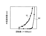
図9に、モータの回転数とロータコア2の外径寸法との関係を示す。ロータコア2の外形寸法は、200mm〜300mmである。横軸はモータ(ロータ)の回転数であり、単位は1000rpmである。縦軸はロータコア2の外径変形量であり、単位はmmである。
N1は、隙間嵌めのロータコアの結果であるが、両端部とあり溝内壁との隙間は大小ばらつきを有している。N2は、本発明のロータコア2の結果である。ロータコア2では、全ての両端部61、62の曲面611、621と、あり溝20、21の曲面201、211は、常に接触した状態にある。
回転数が常用回転数の半分の回転数になると、N1では、外径変形量が0.01mmのオーダーで変形が発生するが、N2では、ほとんど0である。これにより、本発明のロータコア2によれば、回転数が高くなっても外径変形がほとんど発生しないことがわかる。
On the other hand, in order to avoid the shavings generated by press-fitting the
FIG. 9 shows the relationship between the rotational speed of the motor and the outer diameter of the
N1 is the result of the rotor core with a gap fit, but the gap between the both ends and the inner wall of the groove varies in size. N2 is the result of the
When the rotational speed is half the normal rotational speed, deformation occurs in the order of an outer diameter deformation amount of 0.01 mm in N1, but is almost 0 in N2. Thereby, according to the
図2に磁束の流れGを矢印で示す。磁束の流れGは、非磁性体ブリッジ6の端部61a〜61hの近くまで存在すると考えられる。
非磁性体ブリッジ6の個数を1個とした場合には、強度上の必要性より端部61の膨らみ部の大きさがかなり大きくなり、磁束の流れGを遮ってしまい、磁束密度が低下する恐れがある。本実施例では、8本の非磁性体ブリッジ6a〜6hを設けることにより、各別の端部61a〜61hの大きさを小さくしているため、磁束の流れGを遮ることが少なくなっている。
FIG. 2 shows the flow G of magnetic flux with arrows. It is considered that the magnetic flux flow G exists up to the vicinity of the end portions 61 a to 61 h of the
When the number of
以上詳細に説明したように、本実施例のロータの製造方法によれば、(1)中心孔11と、外周部に形成された磁石孔12、13、14とを備えるロータコア2と、磁石孔12、13、14に内蔵された永久磁石3、4、5と、中心孔11に圧入されたロータ軸10とを有するロータ1の製造方法であって、永久磁石からの磁束の漏れを防止するために、ロータコア2に形成された漏れ防止孔15と、漏れ防止孔15の外周側の内壁に形成された外周側あり溝20と、漏れ防止孔15の内周側の内壁に、外周側あり溝20に対向して形成された内周側あり溝21と、両端部61、62が、外周側あり溝20と内周側あり溝21に係合する非磁性体ブリッジ6とを有し、外力(押圧力F)を付加して、外周側の内壁が内周側の内壁に近づくように弾性変形させること、弾性変形させた状態で、非磁性体ブリッジ6を外周側あり溝20と内周側あり溝21に挿入すること、挿入後に、外力を解放すること、を特徴とするので、非磁性体ブリッジ6を一対のあり溝20、21に挿入するときには、非磁性体ブリッジ6と、外周側あり溝20、内周側あり溝21の各々の内壁面との間には隙間があるため、削り屑が発生することを皆無とすることができる。また、漏れ磁束を低減できるため、磁石量を減少させてモータのコストを低減することができる。
また、挿入後に、外力を解放すると、非磁性体ブリッジ6と一対のあり溝20、21の内壁面が一定の力で接触するため、ロータ1に遠心力が作用したときに、ロータコア2の外周部が外側に変形することがなく、ロータ1とステータとの隙間を常に一定に保つことができ、ロータ1の回転に悪影響を与える恐れがない。
As described in detail above, according to the rotor manufacturing method of the present embodiment, (1) the
Further, when the external force is released after the insertion, the
(2)(1)に記載されたロータの製造方法において、磁石用が、ロータコア2の円周方向に形成された第1磁石孔12と、第1磁石孔12の両側にロータコア2の半径方向に形成された第2磁石孔13と第3磁石孔14とを有すること、第2磁石孔13と第3磁石孔14のコア外周に、コア外周繋ぎ部16、17が形成されていること、コア外周繋ぎ部16、17で、弾性変形が生じること、を特徴とするので、外力を付加したときに、一対のコア外周繋ぎ部16、17が弾性変形するため、比較的小さな力で十分な弾性変形を得ることができると共に、外周側内壁が内周側内壁に対して平行に変形するため、少しの弾性変形により、非磁性体ブリッジ6と一対のあり溝20、21の内壁面との隙間を均一に形成することができる。特に、非磁性体ブリッジ6を複数本用いるときには、各々の非磁性体ブリッジ6a〜6hにおいて、均一な隙間を形成することができるため、複数の非磁性体ブリッジ6a〜6hを非接触で挿入することが
(2) In the method for manufacturing a rotor described in (1), the magnet is a
(3)(1)または(2)に記載されたロータの製造方法において、非磁性体ブリッジ6を2本以上とすることにより、非磁性体ブリッジ6の両端部61、62の膨らみ部を小さくし、永久磁石3、4、5の磁束が通過する断面積を大きくしたこと、を特徴とするので、各別の非磁性体ブリッジ6の両端部61、62の大きさを小さくできるため、漏れ防止孔15を必要な面積形成したときに、さらに非磁性体ブリッジ6の両端部61、62が、永久磁石3、4、5の磁束が通過する面積を遮る面積を小さくでき、その結果、永久磁石3、4、5の磁束が通過する断面積を大きくできる。
(3) In the method for manufacturing a rotor described in (1) or (2), the bulge portions of the both
上述した本実施形態は、本発明の要旨を変更しない範囲で変更することができる。
例えば、本実施形態では、非磁性体ブリッジ6を8個用いているが、2個、4個、6個、10個であっても良い。
This embodiment mentioned above can be changed in the range which does not change the summary of this invention.
For example, in the present embodiment, eight
本発明は、ハイブリッド自動車で使用されるモータ用のロータの製造方法として利用可能である。 The present invention can be used as a method for manufacturing a rotor for a motor used in a hybrid vehicle.
1 ロータ
2 ロータコア
3、4、5 永久磁石
6 非磁性体ブリッジ
10 ロータ軸
12 第1磁石孔
13 第2磁石孔
14 第3磁石孔
15 漏れ防止孔
16、17 コア繋ぎ部
20 外周側あり溝
21 内周側あり溝
DESCRIPTION OF
Claims (3)
前記永久磁石からの磁束の漏れを防止するために、前記ロータコアに形成された磁束漏れ防止用孔部と、
前記磁束漏れ防止用孔部の外周側の内壁に形成された外周側あり溝と、前記磁束漏れ防止用孔部の内周側の内壁に、前記外周側あり溝に対向して形成された内周側あり溝と、
両端部が、前記外周側あり溝と前記内周側あり溝に係合する非磁性体ブリッジとを有し、
外力を付加して、前記外周側の内壁が前記内周側の内壁に近づくように弾性変形させること、
前記弾性変形させた状態で、前記非磁性体ブリッジを前記外周側あり溝と前記内周側あり溝に挿入すること、
前記挿入後に、前記外力を解放すること、
を特徴とするロータの製造方法。 In a rotor manufacturing method comprising a rotor core comprising a center hole, a magnet hole formed in the outer peripheral portion, a permanent magnet built in the magnet hole, and a rotor shaft press-fitted into the center hole,
In order to prevent leakage of magnetic flux from the permanent magnet, a magnetic flux leakage prevention hole formed in the rotor core;
An outer circumferential groove formed on the inner wall on the outer circumferential side of the magnetic flux leakage prevention hole, and an inner groove formed on the inner wall on the inner circumferential side of the magnetic flux leakage prevention hole so as to face the outer circumferential groove. A circumferential groove,
Both ends have a non-magnetic bridge that engages with the outer circumferential groove and the inner circumferential groove,
Applying an external force to elastically deform the inner wall on the outer peripheral side so as to approach the inner wall on the inner peripheral side;
Inserting the non-magnetic bridge into the outer peripheral groove and the inner peripheral groove in the elastically deformed state;
Releasing the external force after the insertion;
A method for manufacturing a rotor, characterized in that
前記磁石用孔が、前記ロータコアの円周方向に形成された円周方向磁石用孔と、前記円周方向磁石用孔の両側に前記ロータコアの半径方向に形成された一対の半径方向磁石用孔とを有すること、
前記一対の半径方向磁石用孔のコア外周に、コア外周繋ぎ部が形成されていること、
前記一対の半径方向磁石用孔の前記コア繋ぎ部で、前記弾性変形が生じること、
を特徴とするロータの製造方法。 In the manufacturing method of the rotor according to claim 1,
The magnet hole has a circumferential magnet hole formed in the circumferential direction of the rotor core, and a pair of radial magnet holes formed in the radial direction of the rotor core on both sides of the circumferential magnet hole. Having
A core outer periphery connecting portion is formed on the core outer periphery of the pair of radial magnet holes,
The elastic deformation occurs at the core connecting portion of the pair of radial magnet holes;
A method for manufacturing a rotor, characterized in that
前記非磁性体ブリッジを2本以上とすることにより、前記非磁性体ブリッジの前記両端部の膨らみ部を小さくし、前記永久磁石の磁束が通過する断面積を大きくしたこと、
を特徴とするロータの製造方法。 In the manufacturing method of the rotor according to claim 1 or 2,
By making the number of the non-magnetic bridges two or more, the bulges at the both ends of the non-magnetic bridge are reduced, and the cross-sectional area through which the magnetic flux of the permanent magnet passes is increased.
A method for manufacturing a rotor, characterized in that
Priority Applications (5)
| Application Number | Priority Date | Filing Date | Title |
|---|---|---|---|
| JP2014225339A JP6098614B2 (en) | 2014-11-05 | 2014-11-05 | Manufacturing method of rotor |
| US14/820,962 US9853527B2 (en) | 2014-11-05 | 2015-08-07 | Method for producing a rotor |
| EP15180685.8A EP3018802B1 (en) | 2014-11-05 | 2015-08-12 | Method for producing a rotor |
| KR1020150134500A KR101753479B1 (en) | 2014-11-05 | 2015-09-23 | Method for producing a rotor |
| CN201510617375.7A CN105576914B (en) | 2014-11-05 | 2015-09-24 | The manufacture method of rotor |
Applications Claiming Priority (1)
| Application Number | Priority Date | Filing Date | Title |
|---|---|---|---|
| JP2014225339A JP6098614B2 (en) | 2014-11-05 | 2014-11-05 | Manufacturing method of rotor |
Publications (2)
| Publication Number | Publication Date |
|---|---|
| JP2016092980A JP2016092980A (en) | 2016-05-23 |
| JP6098614B2 true JP6098614B2 (en) | 2017-03-22 |
Family
ID=53800900
Family Applications (1)
| Application Number | Title | Priority Date | Filing Date |
|---|---|---|---|
| JP2014225339A Active JP6098614B2 (en) | 2014-11-05 | 2014-11-05 | Manufacturing method of rotor |
Country Status (5)
| Country | Link |
|---|---|
| US (1) | US9853527B2 (en) |
| EP (1) | EP3018802B1 (en) |
| JP (1) | JP6098614B2 (en) |
| KR (1) | KR101753479B1 (en) |
| CN (1) | CN105576914B (en) |
Families Citing this family (8)
| Publication number | Priority date | Publication date | Assignee | Title |
|---|---|---|---|---|
| JP6137121B2 (en) | 2014-11-07 | 2017-05-31 | トヨタ自動車株式会社 | Rotor structure and rotor manufacturing method |
| JP6206438B2 (en) | 2015-04-01 | 2017-10-04 | トヨタ自動車株式会社 | Laminated rotor and manufacturing method thereof |
| JP6863468B2 (en) * | 2017-09-29 | 2021-04-21 | アイシン・エィ・ダブリュ株式会社 | Manufacturing method of core for rotary electric machine |
| CN107947412A (en) * | 2017-12-25 | 2018-04-20 | 上海联孚新能源科技集团有限公司 | A kind of high intensity permanent-magnetic synchronous motor rotor |
| KR102626959B1 (en) * | 2018-11-13 | 2024-01-19 | 엘지전자 주식회사 | Rotor assembly and motor including the same |
| CN111463936A (en) * | 2019-01-18 | 2020-07-28 | 福特全球技术公司 | Motor rotor |
| DE102020129142B4 (en) | 2020-11-05 | 2022-05-12 | Audi Aktiengesellschaft | Rotor for a rotating electrical machine |
| CN113726046A (en) * | 2021-08-18 | 2021-11-30 | 珠海格力电器股份有限公司 | Rotor punching, rotor, motor and new forms of energy trolley-bus |
Family Cites Families (10)
| Publication number | Priority date | Publication date | Assignee | Title |
|---|---|---|---|---|
| DE2703038C3 (en) * | 1977-01-26 | 1981-09-17 | Metzeler Kautschuk GmbH, 8000 München | Prestressable bearing element |
| JPH10285847A (en) * | 1997-04-09 | 1998-10-23 | Mitsubishi Electric Corp | Permanent-magnet type motor |
| US6122817A (en) | 1997-09-19 | 2000-09-26 | Alliedsignal Inc. | Rotor assembly having lamination stack that is separately piloted and clamped |
| JP2009201269A (en) * | 2008-02-22 | 2009-09-03 | Fuji Electric Systems Co Ltd | Embedded magnet motor and manufacturing method therefor |
| US8330319B2 (en) * | 2008-11-20 | 2012-12-11 | UT Batelle, LLC | Substantially parallel flux uncluttered rotor machines |
| JP5387033B2 (en) * | 2009-02-19 | 2014-01-15 | 新日鐵住金株式会社 | Split rotor and electric motor |
| JP2012161226A (en) * | 2011-02-03 | 2012-08-23 | Toyota Motor Corp | Rotor for rotary electric machine |
| JP5353917B2 (en) * | 2011-02-03 | 2013-11-27 | トヨタ自動車株式会社 | Rotating machine rotor |
| IT1404118B1 (en) * | 2011-02-10 | 2013-11-15 | Magneti Marelli Spa | METHOD OF CONSTRUCTION OF A MAGNETIC CORE CONSTITUTED BY SHEARS PACKED FOR AN ELECTRIC MACHINE |
| US8618708B2 (en) * | 2011-07-29 | 2013-12-31 | General Electric Company | Electrical machine |
-
2014
- 2014-11-05 JP JP2014225339A patent/JP6098614B2/en active Active
-
2015
- 2015-08-07 US US14/820,962 patent/US9853527B2/en active Active
- 2015-08-12 EP EP15180685.8A patent/EP3018802B1/en active Active
- 2015-09-23 KR KR1020150134500A patent/KR101753479B1/en active IP Right Grant
- 2015-09-24 CN CN201510617375.7A patent/CN105576914B/en not_active Expired - Fee Related
Also Published As
| Publication number | Publication date |
|---|---|
| KR20160053768A (en) | 2016-05-13 |
| CN105576914A (en) | 2016-05-11 |
| EP3018802A3 (en) | 2016-06-22 |
| US20160126814A1 (en) | 2016-05-05 |
| CN105576914B (en) | 2017-11-28 |
| EP3018802A2 (en) | 2016-05-11 |
| JP2016092980A (en) | 2016-05-23 |
| KR101753479B1 (en) | 2017-07-03 |
| US9853527B2 (en) | 2017-12-26 |
| EP3018802B1 (en) | 2021-07-28 |
Similar Documents
| Publication | Publication Date | Title |
|---|---|---|
| JP6137121B2 (en) | Rotor structure and rotor manufacturing method | |
| JP6098614B2 (en) | Manufacturing method of rotor | |
| JP6836842B2 (en) | Rotor and motor including it | |
| JP2007049805A (en) | Permanent magnet type rotor | |
| JP5256778B2 (en) | Motor rotor and motor | |
| CN111418131B (en) | Stator core | |
| JP6771745B2 (en) | Rotating machine and manufacturing method of rotating machine | |
| KR102120312B1 (en) | Stator core and motor including stator core | |
| JP6447206B2 (en) | Rotor for rotating electrical machine and method for manufacturing the same | |
| JP6357859B2 (en) | Permanent magnet embedded rotary electric machine | |
| JP6127991B2 (en) | Electric motor | |
| JP5917193B2 (en) | Rotor, motor and method of manufacturing rotor | |
| JP2011205753A (en) | Electric motor, and manufacturing method of rotor of electric motor | |
| JP2018207648A (en) | motor | |
| JP2013187943A (en) | Permanent magnet type motor and rotor thereof | |
| JP2016184991A (en) | Magnet embedded type rotor and manufacturing method of the same | |
| JP2011055688A (en) | Rotor | |
| JP6176379B2 (en) | Permanent magnet rotating electric machine | |
| WO2014118933A1 (en) | Permanent magnet synchronous motor | |
| JP2008022592A (en) | Electric motor | |
| JP2019054684A (en) | motor | |
| JP5359526B2 (en) | Permanent magnet synchronous motor rotor | |
| JP2008054436A (en) | Motor | |
| JP2017017913A (en) | Rotor and permanent magnet synchronous motor | |
| JP2016111787A (en) | Embedded magnet rotor, and manufacturing method of embedded magnet rotor |
Legal Events
| Date | Code | Title | Description |
|---|---|---|---|
| A621 | Written request for application examination |
Free format text: JAPANESE INTERMEDIATE CODE: A621 Effective date: 20160318 |
|
| TRDD | Decision of grant or rejection written | ||
| A01 | Written decision to grant a patent or to grant a registration (utility model) |
Free format text: JAPANESE INTERMEDIATE CODE: A01 Effective date: 20170124 |
|
| A977 | Report on retrieval |
Free format text: JAPANESE INTERMEDIATE CODE: A971007 Effective date: 20170125 |
|
| A61 | First payment of annual fees (during grant procedure) |
Free format text: JAPANESE INTERMEDIATE CODE: A61 Effective date: 20170206 |
|
| R151 | Written notification of patent or utility model registration |
Ref document number: 6098614 Country of ref document: JP Free format text: JAPANESE INTERMEDIATE CODE: R151 |