EP1174747A1 - Support pour éléments filiformes de faible diamètre et faisceau d'éléments filiformes reliés entre eux par ce support - Google Patents
Support pour éléments filiformes de faible diamètre et faisceau d'éléments filiformes reliés entre eux par ce support Download PDFInfo
- Publication number
- EP1174747A1 EP1174747A1 EP01401800A EP01401800A EP1174747A1 EP 1174747 A1 EP1174747 A1 EP 1174747A1 EP 01401800 A EP01401800 A EP 01401800A EP 01401800 A EP01401800 A EP 01401800A EP 1174747 A1 EP1174747 A1 EP 1174747A1
- Authority
- EP
- European Patent Office
- Prior art keywords
- support
- longitudinal
- channels
- filiform
- channel
- Prior art date
- Legal status (The legal status is an assumption and is not a legal conclusion. Google has not performed a legal analysis and makes no representation as to the accuracy of the status listed.)
- Granted
Links
- 239000013307 optical fiber Substances 0.000 claims abstract description 26
- 230000005489 elastic deformation Effects 0.000 claims abstract description 4
- 239000011324 bead Substances 0.000 claims description 3
- 238000003490 calendering Methods 0.000 claims description 3
- 239000012815 thermoplastic material Substances 0.000 claims description 2
- 230000000295 complement effect Effects 0.000 claims 2
- 229910052500 inorganic mineral Inorganic materials 0.000 description 8
- 239000011707 mineral Substances 0.000 description 8
- 229920002994 synthetic fiber Polymers 0.000 description 6
- 239000011347 resin Substances 0.000 description 5
- 229920005989 resin Polymers 0.000 description 5
- VYPSYNLAJGMNEJ-UHFFFAOYSA-N Silicium dioxide Chemical compound O=[Si]=O VYPSYNLAJGMNEJ-UHFFFAOYSA-N 0.000 description 4
- 239000000835 fiber Substances 0.000 description 2
- 230000002093 peripheral effect Effects 0.000 description 2
- 238000006116 polymerization reaction Methods 0.000 description 2
- 238000006243 chemical reaction Methods 0.000 description 1
- 238000001125 extrusion Methods 0.000 description 1
- 238000009434 installation Methods 0.000 description 1
- 239000007788 liquid Substances 0.000 description 1
- 230000014759 maintenance of location Effects 0.000 description 1
- 239000000463 material Substances 0.000 description 1
- 230000000717 retained effect Effects 0.000 description 1
- 239000000377 silicon dioxide Substances 0.000 description 1
- 239000012209 synthetic fiber Substances 0.000 description 1
- 230000008646 thermal stress Effects 0.000 description 1
- 229920001169 thermoplastic Polymers 0.000 description 1
- 239000004416 thermosoftening plastic Substances 0.000 description 1
- 230000000007 visual effect Effects 0.000 description 1
Images
Classifications
-
- G—PHYSICS
- G02—OPTICS
- G02B—OPTICAL ELEMENTS, SYSTEMS OR APPARATUS
- G02B6/00—Light guides; Structural details of arrangements comprising light guides and other optical elements, e.g. couplings
- G02B6/44—Mechanical structures for providing tensile strength and external protection for fibres, e.g. optical transmission cables
- G02B6/4439—Auxiliary devices
- G02B6/4459—Ducts; Conduits; Hollow tubes for air blown fibres
-
- Y—GENERAL TAGGING OF NEW TECHNOLOGICAL DEVELOPMENTS; GENERAL TAGGING OF CROSS-SECTIONAL TECHNOLOGIES SPANNING OVER SEVERAL SECTIONS OF THE IPC; TECHNICAL SUBJECTS COVERED BY FORMER USPC CROSS-REFERENCE ART COLLECTIONS [XRACs] AND DIGESTS
- Y10—TECHNICAL SUBJECTS COVERED BY FORMER USPC
- Y10S—TECHNICAL SUBJECTS COVERED BY FORMER USPC CROSS-REFERENCE ART COLLECTIONS [XRACs] AND DIGESTS
- Y10S439/00—Electrical connectors
- Y10S439/942—Comblike retainer for conductor
Definitions
- the present invention relates to a support for filiform elements of low diameter and a bundle of filiform elements linked together by this support.
- optical fibers usually used in a network of wired telecommunications we usually distinguish mineral optical fibers, generally made of silica, and optical fibers of synthetic material.
- a mineral optical fiber generally comprises a doped silica core coated with an intermediate mineral sheath and a peripheral organic sheath in synthetic material.
- This peripheral sheath generally consists of a first flexible sheath coated with a second hard sheath.
- An optical fiber of this type has commonly a diameter of 250 micrometers.
- Synthetic fiber is usually larger than a mineral optical fiber.
- the current diameter of an optical fiber in material synthetic is usually 500 micrometers and can reach, in some cases, 1 millimeter.
- the different optical fibers of a bundle are usually identified by a color code.
- the resin ribbon in which the fibers are embedded optics is generally transparent, so that an operator can identify each optical fiber from its color.
- the polymerization of the ribbon resin is a reaction exothermic likely to generate harmful thermal stresses in the fibers optics surrounded by resin.
- the object of the invention is to connect filiform elements of small diameter, such as as optical fibers or coaxial electrical cables, using means allowing to facilitate access to each filiform element and, where appropriate, the identification of the different bundles and filiform elements.
- the subject of the invention is a support for filiform elements of small diameter less than or equal to 1 millimeter, in particular optical fibers and / or coaxial electrical cables, characterized in that it comprises longitudinal channels intended to accommodate each a filiform element, each channel being delimited by two longitudinal walls connected to each other by a core and delimiting a longitudinal opening of the channel, the width of this longitudinal opening varying by elastic deformation of the longitudinal walls between a configuration of access to the channel allowing the passage of a filiform element through this opening and a configuration for retaining a filiform element in the channel.
- the invention also relates to an assembly of at least two supports each as defined above, characterized in that each support comprises a longitudinal wall delimiting a lateral edge of the support provided with hooking means intended to cooperate with means of additional hanging carried by another support.
- the attachment means of the two supports cooperate with one another by snap-fastening.
- the invention also relates to a bundle of filiform elements of small diameter less than or equal to 1 millimeter, characterized in that the filiform elements are interconnected by a support as defined above.
- the filiform elements are chosen from optical fibers and coaxial electrical cables.
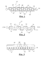
- FIG. 1 There is shown in Figures 1 and 2 a support 10 according to a first mode for carrying out the invention for filiform elements 12 of small smaller diameter or equal to one millimeter.
- the filiform elements 12 are optical fibers classics intended to be used for example in a telecommunications network.
- the optical fibers 12 are made of a mineral or synthetic material.
- a mineral type optical fiber for example comprises a coated doped silica core a first mineral sheath and a second organic sheath comprising usually two layers of synthetic material.
- the filiform elements 12 may consist of cables electric coaxials such as those usually used in telecommunications or medical devices.
- the support 10 is intended to preferably carry a dozen elements filiform 12. However, the number of filiform elements 12 carried by the support can be less than or more than a dozen.
- the support 10 generally planar and elongated, comprises channels longitudinal 14 each intended to house a threadlike element 12.
- Each channel 14 is delimited by two longitudinal walls 18 connected between them by a core 20.
- the longitudinal walls 18 of the same channel 14 define a longitudinal opening 22.
- the width of this longitudinal opening 22 varies by elastic deformation of the longitudinal walls 18 between a configuration of access to the channel 14, as shown in Figure 2, allowing the passage of an element filiform 12 through this opening 22, and a configuration for retaining an element filiform 12 in channel 14, as shown in FIG. 1.
- the openings longitudinal 22 of the successive channels 14 open out alternately in faces opposite of the support 10.
- the webs 20 of the channels alternate with the walls longitudinal 18 of these channels so as to define a cross section of the support 10 in boustrophedon.
- the channels 14 each have a substantially triangular cross section when their longitudinal opening 22 is in the retaining configuration.
- the thickness of the longitudinal walls 18 and of the cores 20 is preferably between 20 and 50 micrometers.
- the support 10 is made of synthetic material, preferably thermoplastic, using conventional means such as extrusion means profiles or calendering means.
- the support 10 comprises two longitudinal walls each delimiting a lateral edge of this support 10. Each side edge is provided with hooking means 24, 26 intended to cooperate with additional attachment means carried by another support similar to the support 10 illustrated in FIGS. 1 and 2.
- Two similar supports 10 can thus be juxtaposed laterally so as to form a set of supports carrying filiform elements 12.
- FIG 1 there is shown a side edge of the support 10 (on the right in considering the figure) provided with a female hooking member 24 intended to cooperate by latching with a male attachment member 26 of another support 10, such as the male member 26 carried by the left lateral edge of the support 10 shown in the figure 1.
- the invention therefore makes it possible to form bundles of filiform elements 12 of small diameter less than or equal to one millimeter by connecting these elements with at least one support 10.
- the longitudinal openings 22 of the channels allow access visually to the filiform elements 12 contained in these channels so as to see their color and identify them.
- the support 10 need not be transparent.
- This support 10 can therefore be of varied color which makes it possible to distinguish each support 10 in a set of supports by means of a color code and, where appropriate, combine the color code of the filiform elements 12 with the color code of the supports 10.
- the placement of the filiform elements in the channels of the support can be performed for example by forcing the filiform elements 12 through the longitudinal openings 22 so as to separate the side walls 18.
- This introduction force can be achieved using rollers driving the filiform elements 12 into the longitudinal openings 22.
- FIG 2 there is shown a support 10 for filiform elements 12 according to a second embodiment of the invention.
- the openings longitudinal 22 of the successive channels 14 open into the same face of the support 10.
- the longitudinal walls 18 each have a free edge provided with a bead 28 for retaining the filiform elements 12.
- the face of the support into which the openings open longitudinal 22 of the channels 14 is provided with a cover 30 for closing the channels 14.
- the channels 14 of the support have dimensions adapted to retain in particular mineral type optical fibers, usually having a diameter of 250 micrometers, and of synthetic type, usually having a diameter of 500 micrometers.
- the support according to the invention can also connect cables together coaxial having dimensions similar to those of the optical fibers mentioned above.
- the support according to the invention is well suited for connecting together filiform elements having a diameter less than or equal to 1 millimeter.
Landscapes
- Physics & Mathematics (AREA)
- General Physics & Mathematics (AREA)
- Optics & Photonics (AREA)
- Light Guides In General And Applications Therefor (AREA)
- Optical Fibers, Optical Fiber Cores, And Optical Fiber Bundles (AREA)
- Installation Of Indoor Wiring (AREA)
- Particle Accelerators (AREA)
- Connection Of Plates (AREA)
- Clamps And Clips (AREA)
- Mutual Connection Of Rods And Tubes (AREA)
- Insertion, Bundling And Securing Of Wires For Electric Apparatuses (AREA)
- Details Of Indoor Wiring (AREA)
- Preliminary Treatment Of Fibers (AREA)
- Spinning Or Twisting Of Yarns (AREA)
Abstract
Description
- les ouvertures longitudinales des canaux successifs débouchent alternativement dans des faces opposées du support, les âmes des canaux alternant avec les parois longitudinales de ces canaux de façon à délimiter une section transversale du support en boustrophédon ;
- les canaux longitudinaux ont chacun une section transversale sensiblement triangulaire lorsque leur ouverture longitudinale est en configuration de retenue ;
- les ouvertures longitudinales des canaux successifs débouchent dans une même face du support ;
- les parois latérales comportent chacune un bord libre muni d'un bourrelet de retenue des éléments filiformes dans les canaux ;
- la face du support dans laquelle débouchent les ouvertures longitudinales des canaux est munie d'un couvercle d'obturation des canaux amovible ;
- le support est fabriqué dans une matière thermoplastique extrudée ou calandrée.
- les figures 1 et 2 sont des vues schématiques en coupe transversale d'un support pour éléments filiformes, selon un premier mode de réalisation de l'invention, dans lesquelles chaque ouverture longitudinale d'un canal est respectivement dans une configuration d'accès à ce canal et dans une configuration de retenue d'un élément filiforme dans ce canal ;
- la figure 3 est une vue schématique en coupe transversale d'un support pour élément filiforme selon un second mode de réalisation de l'invention.
Claims (11)
- Support pour éléments filiformes (12) de faible diamètre inférieur ou égal à 1 millimètre, notamment des fibres optiques et/ou des câbles électriques coaxiaux, caractérisé en ce qu'il comprend des canaux longitudinaux (14) destinés à loger chacun un élément filiforme (12), chaque canal (14) étant délimité par deux parois longitudinales (18) reliées entre elles par une âme (20) et délimitant une ouverture longitudinale (22) du canal, la largeur de cette ouverture longitudinale (22) variant par déformation élastique des parois longitudinales (18) entre une configuration d'accès au canal (14) autorisant le passage d'un élément filiforme (12) à travers cette ouverture (22), et une configuration de retenue d'un élément filiforme (12) dans le canal (14).
- Support selon la revendication 1, caractérisé en ce que les ouvertures longitudinales (22) des canaux successifs (14) débouchent alternativement dans des faces opposées du support (10), les âmes (20) des canaux (14) alternant avec les parois longitudinales (18) de ces canaux (14) de façon à délimiter une section transversale du support (10) en boustrophédon.
- Support selon la revendication 2, caractérisé en ce que les canaux longitudinaux (14) ont chacun une section transversale sensiblement triangulaire lorsque leur ouverture longitudinale (22) est en configuration de retenue.
- Support selon la revendication 1, caractérisé en ce que les ouvertures longitudinales (22) des canaux successifs (14) débouchent dans une même face du support (10).
- Support selon la revendication 4, caractérisé en ce que les parois latérales (18) comportent chacune un bord libre muni d'un bourrelet (28) de retenue des éléments filiformes (12) dans les canaux (14).
- Support selon la revendication 4 ou 5, caractérisé en ce que la face du support (10) dans laquelle débouchent les ouvertures longitudinales (22) des canaux est munie d'un couvercle (30) d'obturation des canaux (14) amovible.
- Support selon l'une quelconque des revendications 1 à 6, caractérisé en ce qu'il est fabriqué dans une matière thermoplastique extrudée ou calandrée.
- Ensemble d'au moins deux supports chacun selon l'une quelconque des revendications précédentes, caractérisé en ce que chaque support (10) comprend une paroi longitudinale (18) délimitant un bord latéral du support munie de moyens d'accrochage (24, 26) destinés à coopérer avec des moyens d'accrochage complémentaires (26, 24) portés par un autre support (10).
- Ensemble selon la revendication 8, caractérisé en ce que les moyens d'accrochage complémentaires (24, 26) des deux supports coopèrent entre eux par encliquetage.
- Faisceau d'éléments filiformes de faible diamètre inférieur ou égal à 1 millimètre, caractérisé en ce que les éléments filiformes (12) sont reliés entre eux par un support (10) selon l'une quelconque des revendications 1 à 7.
- Faisceau selon la revendication 10, caractérisé en ce que les éléments filiformes (12) sont choisis parmi les fibres optiques et les câbles électriques coaxiaux.
Applications Claiming Priority (2)
| Application Number | Priority Date | Filing Date | Title |
|---|---|---|---|
| FR0009201 | 2000-07-13 | ||
| FR0009201A FR2811816B1 (fr) | 2000-07-13 | 2000-07-13 | Support pour elements filiformes de faible diametre et faisceau d'elements filiformes relies entre eux par ce support |
Publications (2)
| Publication Number | Publication Date |
|---|---|
| EP1174747A1 true EP1174747A1 (fr) | 2002-01-23 |
| EP1174747B1 EP1174747B1 (fr) | 2008-09-10 |
Family
ID=8852472
Family Applications (1)
| Application Number | Title | Priority Date | Filing Date |
|---|---|---|---|
| EP01401800A Expired - Lifetime EP1174747B1 (fr) | 2000-07-13 | 2001-07-05 | Support pour éléments filiformes de faible diamètre et faisceau d'éléments filiformes reliés entre eux par ce support |
Country Status (6)
| Country | Link |
|---|---|
| US (1) | US6580867B2 (fr) |
| EP (1) | EP1174747B1 (fr) |
| JP (1) | JP2002134949A (fr) |
| AT (1) | ATE408165T1 (fr) |
| DE (1) | DE60135707D1 (fr) |
| FR (1) | FR2811816B1 (fr) |
Cited By (2)
| Publication number | Priority date | Publication date | Assignee | Title |
|---|---|---|---|---|
| EP2009337A2 (fr) | 2007-06-26 | 2008-12-31 | AZ Industrietechnik GmbH & Co. KG | Agencement et procédé de fixation de conduites |
| EP2860478A4 (fr) * | 2012-06-07 | 2016-01-20 | Samsung Electronics Co Ltd | Réfrigérateur |
Families Citing this family (35)
| Publication number | Priority date | Publication date | Assignee | Title |
|---|---|---|---|---|
| US6576591B1 (en) * | 2000-10-26 | 2003-06-10 | Nortel Networks Limited | Optical fiber coating and coding scheme |
| US6795633B2 (en) * | 2002-03-28 | 2004-09-21 | Corning Incorporated | Method and apparatus for handling optical components |
| US20060169482A1 (en) * | 2004-07-28 | 2006-08-03 | Hess Mark N | Adhesive backed mount strip |
| US20070114339A1 (en) * | 2005-11-22 | 2007-05-24 | Winchester Mary A | Flexible conduit storage organizer |
| US7635812B2 (en) * | 2006-05-19 | 2009-12-22 | Cvc Limited 1 Llc | Conductor raceway separator |
| US20070280619A1 (en) * | 2006-05-23 | 2007-12-06 | Conner Mark E | Multi-directional optical splice organizer |
| USD568723S1 (en) | 2006-07-11 | 2008-05-13 | Morgan Wayne B | Wire organizer |
| DE102006034236B3 (de) * | 2006-07-25 | 2008-05-15 | Airbus Deutschland Gmbh | Halterung für Lichtwellenleiter |
| US8798427B2 (en) | 2007-09-05 | 2014-08-05 | Corning Cable Systems Llc | Fiber optic terminal assembly |
| EP2344915A4 (fr) | 2008-10-09 | 2015-01-21 | Corning Cable Sys Llc | Terminal à fibre optique ayant un panneau adaptateur portant à la fois les fibres d'entrée et de sortie provenant d'un diviseur optique |
| US8879882B2 (en) | 2008-10-27 | 2014-11-04 | Corning Cable Systems Llc | Variably configurable and modular local convergence point |
| EP2237091A1 (fr) | 2009-03-31 | 2010-10-06 | Corning Cable Systems LLC | Terminal à fibres optiques pouvant être assemblé de manière amovible |
| US8467651B2 (en) | 2009-09-30 | 2013-06-18 | Ccs Technology Inc. | Fiber optic terminals configured to dispose a fiber optic connection panel(s) within an optical fiber perimeter and related methods |
| US9547144B2 (en) | 2010-03-16 | 2017-01-17 | Corning Optical Communications LLC | Fiber optic distribution network for multiple dwelling units |
| US8792767B2 (en) | 2010-04-16 | 2014-07-29 | Ccs Technology, Inc. | Distribution device |
| AU2011317244A1 (en) | 2010-10-19 | 2013-05-23 | Corning Cable Systems Llc | Transition box for multiple dwelling unit fiber optic distribution network |
| US20120281958A1 (en) * | 2011-05-05 | 2012-11-08 | 3M Innovative Properties Company | Re-enterable cabling system for in-building applications |
| US20130108220A1 (en) * | 2011-10-31 | 2013-05-02 | Marco Antonio Gonzalez Garcia | Systems and methods for providing a ferrule boot |
| US9219546B2 (en) | 2011-12-12 | 2015-12-22 | Corning Optical Communications LLC | Extremely high frequency (EHF) distributed antenna systems, and related components and methods |
| JP5916368B2 (ja) * | 2011-12-16 | 2016-05-11 | Sus株式会社 | ケーブルホルダ |
| US10110307B2 (en) | 2012-03-02 | 2018-10-23 | Corning Optical Communications LLC | Optical network units (ONUs) for high bandwidth connectivity, and related components and methods |
| US9004778B2 (en) | 2012-06-29 | 2015-04-14 | Corning Cable Systems Llc | Indexable optical fiber connectors and optical fiber connector arrays |
| US9049500B2 (en) | 2012-08-31 | 2015-06-02 | Corning Cable Systems Llc | Fiber optic terminals, systems, and methods for network service management |
| US8909019B2 (en) | 2012-10-11 | 2014-12-09 | Ccs Technology, Inc. | System comprising a plurality of distribution devices and distribution device |
| US9732884B1 (en) * | 2013-09-16 | 2017-08-15 | Gerard Keller | Polymer locking spacer system |
| DE102014007104B3 (de) * | 2014-05-15 | 2015-08-27 | MENTOR GmbH & Co Präzisions-Bauteile KG | Mehrfach-Halterung mit einer Mehrzahl von Aufnahmen für Lichtleiter |
| JP6455361B2 (ja) * | 2015-08-20 | 2019-01-23 | 株式会社オートネットワーク技術研究所 | 通信用コネクタ及び電線付き通信用コネクタ |
| EP3539191A4 (fr) | 2016-11-11 | 2020-07-01 | Commscope Technologies LLC | Adaptateur pour le montage de câbles et de porte-câbles |
| US10823312B2 (en) | 2016-11-30 | 2020-11-03 | Commscope Technologies Llc | Hanger for mounting multiple cables |
| WO2018111513A1 (fr) | 2016-12-14 | 2018-06-21 | Commscope Technologies Llc | Insert pour le montage de multiples câbles dans un dispositif de suspension de câble |
| WO2018118528A1 (fr) * | 2016-12-21 | 2018-06-28 | Commscope Technologies Llc | Dispositif de suspension servant au montage de multiples câbles |
| CN114421391A (zh) | 2017-01-19 | 2022-04-29 | 康普技术有限责任公司 | 用于安装多根线缆的吊架组件 |
| MX2020001074A (es) * | 2019-02-01 | 2021-03-25 | Ortronics Inc | Ensamblajes de envoltorio para aplicaciones de fibra optica. |
| JP7396016B2 (ja) * | 2019-12-17 | 2023-12-12 | 株式会社椿本チエイン | ケーブル類保護案内装置 |
| GB202016972D0 (en) * | 2020-10-26 | 2020-12-09 | Linian Lab Ltd | Optical fibre clip |
Citations (4)
| Publication number | Priority date | Publication date | Assignee | Title |
|---|---|---|---|---|
| JPS5356043A (en) * | 1976-10-30 | 1978-05-22 | Showa Electric Wire & Cable Co | Optical fiber cable |
| EP0019026A1 (fr) * | 1979-05-11 | 1980-11-26 | Societe Industrielle De Liaisons Electriques - Silec | Elément de câblage pour la réalisation d'éléments de câbles unitaires à fibres optiques, et procédé de fabrication |
| DE4405066C1 (de) * | 1994-02-17 | 1995-05-24 | Siemens Ag | Zugabfangung für Lichtwellenleiter-Hohladern |
| WO1996038752A1 (fr) * | 1995-05-30 | 1996-12-05 | The Whitaker Corporation | Boitier d'epissure de fibre optique et reducteur de contrainte |
Family Cites Families (11)
| Publication number | Priority date | Publication date | Assignee | Title |
|---|---|---|---|---|
| FR19026E (fr) | 1912-03-12 | 1914-09-01 | Charles Constant Genet | Chaudière de chauffage à eau chaude à vitesse accélérée |
| GB2237121B (en) * | 1989-10-10 | 1993-07-21 | Bowthorpe Hellermann Ltd | Optical fibre splice storage enclosure |
| US5146532A (en) * | 1990-11-20 | 1992-09-08 | Scientific-Atlanta, Inc. | Optical fiber retention device |
| US5566269A (en) * | 1995-05-30 | 1996-10-15 | The Whitaker Corporation | Strain relieving holder for optical fiber cable |
| US5566268A (en) * | 1995-05-30 | 1996-10-15 | The Whitaker Corporation | Strain relieving holder for optical fiber cable |
| US5625737A (en) * | 1995-12-11 | 1997-04-29 | Lucent Technologies Inc. | Optical fiber holder and method using same |
| US6240236B1 (en) * | 1999-07-30 | 2001-05-29 | Lucent Technologies, Inc. | High density splice holder |
| US6195496B1 (en) * | 1999-07-30 | 2001-02-27 | Lucent Technologies, Inc. | Splice holder with tilted mounting feature |
| US6353697B1 (en) * | 1999-07-30 | 2002-03-05 | Lucent Technologies, Inc. | Modular layered splice holder |
| US6249636B1 (en) * | 1999-09-07 | 2001-06-19 | Lucent Technologies, Inc. | High density fusion splice holder |
| US6259851B1 (en) * | 1999-09-17 | 2001-07-10 | Lucent Technologies Inc. | High density fiber splice holder |
-
2000
- 2000-07-13 FR FR0009201A patent/FR2811816B1/fr not_active Expired - Fee Related
-
2001
- 2001-07-05 AT AT01401800T patent/ATE408165T1/de not_active IP Right Cessation
- 2001-07-05 EP EP01401800A patent/EP1174747B1/fr not_active Expired - Lifetime
- 2001-07-05 DE DE60135707T patent/DE60135707D1/de not_active Expired - Fee Related
- 2001-07-10 JP JP2001208847A patent/JP2002134949A/ja not_active Withdrawn
- 2001-07-12 US US09/902,782 patent/US6580867B2/en not_active Expired - Fee Related
Patent Citations (4)
| Publication number | Priority date | Publication date | Assignee | Title |
|---|---|---|---|---|
| JPS5356043A (en) * | 1976-10-30 | 1978-05-22 | Showa Electric Wire & Cable Co | Optical fiber cable |
| EP0019026A1 (fr) * | 1979-05-11 | 1980-11-26 | Societe Industrielle De Liaisons Electriques - Silec | Elément de câblage pour la réalisation d'éléments de câbles unitaires à fibres optiques, et procédé de fabrication |
| DE4405066C1 (de) * | 1994-02-17 | 1995-05-24 | Siemens Ag | Zugabfangung für Lichtwellenleiter-Hohladern |
| WO1996038752A1 (fr) * | 1995-05-30 | 1996-12-05 | The Whitaker Corporation | Boitier d'epissure de fibre optique et reducteur de contrainte |
Cited By (4)
| Publication number | Priority date | Publication date | Assignee | Title |
|---|---|---|---|---|
| EP2009337A2 (fr) | 2007-06-26 | 2008-12-31 | AZ Industrietechnik GmbH & Co. KG | Agencement et procédé de fixation de conduites |
| EP2009337A3 (fr) * | 2007-06-26 | 2012-05-30 | AZ Vermögensverwaltung GmbH & Co. KG. | Agencement et procédé de fixation de conduites |
| EP2860478A4 (fr) * | 2012-06-07 | 2016-01-20 | Samsung Electronics Co Ltd | Réfrigérateur |
| US9528747B2 (en) | 2012-06-07 | 2016-12-27 | Samsung Electronics Co., Ltd. | Refrigerator |
Also Published As
| Publication number | Publication date |
|---|---|
| JP2002134949A (ja) | 2002-05-10 |
| US6580867B2 (en) | 2003-06-17 |
| FR2811816A1 (fr) | 2002-01-18 |
| FR2811816B1 (fr) | 2002-10-11 |
| DE60135707D1 (de) | 2008-10-23 |
| EP1174747B1 (fr) | 2008-09-10 |
| ATE408165T1 (de) | 2008-09-15 |
| US20020006262A1 (en) | 2002-01-17 |
Similar Documents
| Publication | Publication Date | Title |
|---|---|---|
| EP1174747B1 (fr) | Support pour éléments filiformes de faible diamètre et faisceau d'éléments filiformes reliés entre eux par ce support | |
| EP0185923B1 (fr) | Support de raccordement de fibres optiques | |
| US10598886B2 (en) | Cable pulling assembly | |
| EP0479226B1 (fr) | Cassette de raccordement optique | |
| EP0716324B1 (fr) | Dispostif de maintien d'au moins un câble à fibres optiques et boitier d'épissurage en faisant application | |
| EP1315009B1 (fr) | Module de distribution et de connexion de fibres optiques destiné à un répartiteur optique | |
| EP0063506A1 (fr) | Dispositif de protection de fibres optiques dégagées à l'extrémité d'un élément de câble, élément de câble muni de ce dispositif, et utilisation d'un tel élément de câble | |
| EP0253728A1 (fr) | Dispositif de réserve pour fibres optiques | |
| FR2748576A1 (fr) | Dispositif pour lover des rubans ou des micro-gaines de fibres optiques, et leurs epissures ou coupleurs de raccordement | |
| FR2523318A1 (fr) | Connecteur pour guides d'ondes lumineuses | |
| FR2520517A1 (fr) | Appareil pour organiser des epissures de cables en fibres optiques | |
| FR2698180A1 (fr) | Porte-épissure de fibres optiques pour cordons de fibres optiques en forme de rubans. | |
| EP0330571B1 (fr) | Dispositif de rétention mécanique pour câble à fibres optiques à structure libre | |
| FR2913776A1 (fr) | Cable optique de raccordement a un reseau de distribution general et procede de raccordement dudit cable | |
| FR2590417A1 (fr) | Agregat de tubes compose d'une pluralite de tubes en matiere plastique | |
| EP3035098B1 (fr) | Dispositif de dérivation d'un câble optique | |
| EP1054279A1 (fr) | Boítier d'accès à une ou plusieurs fibres optiques dans un câble tendu | |
| EP3729156B1 (fr) | Cable optique a elements de dechirements | |
| FR2726914A1 (fr) | Cassette pour le logement et la protection d'une fibre optique et dispositif pour le stockage d'une pluralite de telles cassettes | |
| EP3221730B1 (fr) | Dispositif permettant de connecter un câble à fibre optique et un tube protecteur | |
| EP0637115B1 (fr) | Conduit de protection à friction réduite | |
| FR2633402A1 (fr) | Conducteur optique resistant a la traction | |
| FR2749406A1 (fr) | Dispositif de transition de pas, notamment pour fibres optiques | |
| EP0855721A1 (fr) | Cable a fibres optiques | |
| FR2745393A1 (fr) | Dispositif de support d'epissures, notamment pour fibres ou modules optiques |
Legal Events
| Date | Code | Title | Description |
|---|---|---|---|
| PUAI | Public reference made under article 153(3) epc to a published international application that has entered the european phase |
Free format text: ORIGINAL CODE: 0009012 |
|
| AK | Designated contracting states |
Kind code of ref document: A1 Designated state(s): AT BE CH CY DE DK ES FI FR GB GR IE IT LI LU MC NL PT SE TR |
|
| AX | Request for extension of the european patent |
Free format text: AL;LT;LV;MK;RO;SI |
|
| 17P | Request for examination filed |
Effective date: 20020723 |
|
| AKX | Designation fees paid |
Free format text: AT BE CH CY DE DK ES FI FR GB GR IE IT LI LU MC NL PT SE TR |
|
| RAP1 | Party data changed (applicant data changed or rights of an application transferred) |
Owner name: DRAKA COMTEQ B.V. |
|
| RAP1 | Party data changed (applicant data changed or rights of an application transferred) |
Owner name: DRAKA COMTEQ B.V. |
|
| RAP1 | Party data changed (applicant data changed or rights of an application transferred) |
Owner name: DRAKA COMTEQ B.V. |
|
| GRAP | Despatch of communication of intention to grant a patent |
Free format text: ORIGINAL CODE: EPIDOSNIGR1 |
|
| GRAS | Grant fee paid |
Free format text: ORIGINAL CODE: EPIDOSNIGR3 |
|
| GRAA | (expected) grant |
Free format text: ORIGINAL CODE: 0009210 |
|
| AK | Designated contracting states |
Kind code of ref document: B1 Designated state(s): AT BE CH CY DE DK ES FI FR GB GR IE IT LI LU MC NL PT SE TR |
|
| REG | Reference to a national code |
Ref country code: GB Ref legal event code: FG4D Free format text: NOT ENGLISH |
|
| REG | Reference to a national code |
Ref country code: CH Ref legal event code: EP |
|
| REG | Reference to a national code |
Ref country code: IE Ref legal event code: FG4D Free format text: LANGUAGE OF EP DOCUMENT: FRENCH |
|
| REF | Corresponds to: |
Ref document number: 60135707 Country of ref document: DE Date of ref document: 20081023 Kind code of ref document: P |
|
| PG25 | Lapsed in a contracting state [announced via postgrant information from national office to epo] |
Ref country code: FI Free format text: LAPSE BECAUSE OF FAILURE TO SUBMIT A TRANSLATION OF THE DESCRIPTION OR TO PAY THE FEE WITHIN THE PRESCRIBED TIME-LIMIT Effective date: 20080910 Ref country code: AT Free format text: LAPSE BECAUSE OF FAILURE TO SUBMIT A TRANSLATION OF THE DESCRIPTION OR TO PAY THE FEE WITHIN THE PRESCRIBED TIME-LIMIT Effective date: 20080910 |
|
| NLV1 | Nl: lapsed or annulled due to failure to fulfill the requirements of art. 29p and 29m of the patents act | ||
| REG | Reference to a national code |
Ref country code: IE Ref legal event code: FD4D |
|
| PG25 | Lapsed in a contracting state [announced via postgrant information from national office to epo] |
Ref country code: IE Free format text: LAPSE BECAUSE OF FAILURE TO SUBMIT A TRANSLATION OF THE DESCRIPTION OR TO PAY THE FEE WITHIN THE PRESCRIBED TIME-LIMIT Effective date: 20080910 Ref country code: ES Free format text: LAPSE BECAUSE OF FAILURE TO SUBMIT A TRANSLATION OF THE DESCRIPTION OR TO PAY THE FEE WITHIN THE PRESCRIBED TIME-LIMIT Effective date: 20081221 |
|
| PG25 | Lapsed in a contracting state [announced via postgrant information from national office to epo] |
Ref country code: NL Free format text: LAPSE BECAUSE OF FAILURE TO SUBMIT A TRANSLATION OF THE DESCRIPTION OR TO PAY THE FEE WITHIN THE PRESCRIBED TIME-LIMIT Effective date: 20080910 Ref country code: PT Free format text: LAPSE BECAUSE OF FAILURE TO SUBMIT A TRANSLATION OF THE DESCRIPTION OR TO PAY THE FEE WITHIN THE PRESCRIBED TIME-LIMIT Effective date: 20090210 |
|
| PLBE | No opposition filed within time limit |
Free format text: ORIGINAL CODE: 0009261 |
|
| STAA | Information on the status of an ep patent application or granted ep patent |
Free format text: STATUS: NO OPPOSITION FILED WITHIN TIME LIMIT |
|
| PG25 | Lapsed in a contracting state [announced via postgrant information from national office to epo] |
Ref country code: DK Free format text: LAPSE BECAUSE OF FAILURE TO SUBMIT A TRANSLATION OF THE DESCRIPTION OR TO PAY THE FEE WITHIN THE PRESCRIBED TIME-LIMIT Effective date: 20080910 |
|
| 26N | No opposition filed |
Effective date: 20090611 |
|
| PG25 | Lapsed in a contracting state [announced via postgrant information from national office to epo] |
Ref country code: IT Free format text: LAPSE BECAUSE OF FAILURE TO SUBMIT A TRANSLATION OF THE DESCRIPTION OR TO PAY THE FEE WITHIN THE PRESCRIBED TIME-LIMIT Effective date: 20080910 |
|
| PGFP | Annual fee paid to national office [announced via postgrant information from national office to epo] |
Ref country code: FR Payment date: 20090716 Year of fee payment: 9 |
|
| PGFP | Annual fee paid to national office [announced via postgrant information from national office to epo] |
Ref country code: DE Payment date: 20090722 Year of fee payment: 9 Ref country code: GB Payment date: 20090720 Year of fee payment: 9 |
|
| PG25 | Lapsed in a contracting state [announced via postgrant information from national office to epo] |
Ref country code: SE Free format text: LAPSE BECAUSE OF FAILURE TO SUBMIT A TRANSLATION OF THE DESCRIPTION OR TO PAY THE FEE WITHIN THE PRESCRIBED TIME-LIMIT Effective date: 20081210 |
|
| BERE | Be: lapsed |
Owner name: DRAKA COMTEQ B.V. Effective date: 20090731 |
|
| PG25 | Lapsed in a contracting state [announced via postgrant information from national office to epo] |
Ref country code: MC Free format text: LAPSE BECAUSE OF NON-PAYMENT OF DUE FEES Effective date: 20090731 |
|
| REG | Reference to a national code |
Ref country code: CH Ref legal event code: PL |
|
| PG25 | Lapsed in a contracting state [announced via postgrant information from national office to epo] |
Ref country code: LI Free format text: LAPSE BECAUSE OF NON-PAYMENT OF DUE FEES Effective date: 20090731 Ref country code: CH Free format text: LAPSE BECAUSE OF NON-PAYMENT OF DUE FEES Effective date: 20090731 |
|
| PG25 | Lapsed in a contracting state [announced via postgrant information from national office to epo] |
Ref country code: BE Free format text: LAPSE BECAUSE OF NON-PAYMENT OF DUE FEES Effective date: 20090731 |
|
| PG25 | Lapsed in a contracting state [announced via postgrant information from national office to epo] |
Ref country code: GR Free format text: LAPSE BECAUSE OF FAILURE TO SUBMIT A TRANSLATION OF THE DESCRIPTION OR TO PAY THE FEE WITHIN THE PRESCRIBED TIME-LIMIT Effective date: 20081211 |
|
| GBPC | Gb: european patent ceased through non-payment of renewal fee |
Effective date: 20100705 |
|
| REG | Reference to a national code |
Ref country code: FR Ref legal event code: ST Effective date: 20110331 |
|
| PG25 | Lapsed in a contracting state [announced via postgrant information from national office to epo] |
Ref country code: DE Free format text: LAPSE BECAUSE OF NON-PAYMENT OF DUE FEES Effective date: 20110201 Ref country code: LU Free format text: LAPSE BECAUSE OF NON-PAYMENT OF DUE FEES Effective date: 20090705 |
|
| REG | Reference to a national code |
Ref country code: DE Ref legal event code: R119 Ref document number: 60135707 Country of ref document: DE Effective date: 20110201 |
|
| PG25 | Lapsed in a contracting state [announced via postgrant information from national office to epo] |
Ref country code: FR Free format text: LAPSE BECAUSE OF NON-PAYMENT OF DUE FEES Effective date: 20100802 |
|
| PG25 | Lapsed in a contracting state [announced via postgrant information from national office to epo] |
Ref country code: GB Free format text: LAPSE BECAUSE OF NON-PAYMENT OF DUE FEES Effective date: 20100705 |
|
| PG25 | Lapsed in a contracting state [announced via postgrant information from national office to epo] |
Ref country code: TR Free format text: LAPSE BECAUSE OF FAILURE TO SUBMIT A TRANSLATION OF THE DESCRIPTION OR TO PAY THE FEE WITHIN THE PRESCRIBED TIME-LIMIT Effective date: 20080910 |
|
| PG25 | Lapsed in a contracting state [announced via postgrant information from national office to epo] |
Ref country code: CY Free format text: LAPSE BECAUSE OF FAILURE TO SUBMIT A TRANSLATION OF THE DESCRIPTION OR TO PAY THE FEE WITHIN THE PRESCRIBED TIME-LIMIT Effective date: 20080910 |