EP1174635A1 - Dispositif de réglage pour frein à tambour avec un dispositif de commutation dépendante de la température - Google Patents
Dispositif de réglage pour frein à tambour avec un dispositif de commutation dépendante de la température Download PDFInfo
- Publication number
- EP1174635A1 EP1174635A1 EP01114961A EP01114961A EP1174635A1 EP 1174635 A1 EP1174635 A1 EP 1174635A1 EP 01114961 A EP01114961 A EP 01114961A EP 01114961 A EP01114961 A EP 01114961A EP 1174635 A1 EP1174635 A1 EP 1174635A1
- Authority
- EP
- European Patent Office
- Prior art keywords
- brake
- temperature
- wedge
- adjustment
- pressure strut
- Prior art date
- Legal status (The legal status is an assumption and is not a legal conclusion. Google has not performed a legal analysis and makes no representation as to the accuracy of the status listed.)
- Granted
Links
- 230000001419 dependent effect Effects 0.000 title claims abstract description 15
- 239000000463 material Substances 0.000 claims description 14
- 238000006073 displacement reaction Methods 0.000 claims description 10
- 230000000903 blocking effect Effects 0.000 claims description 9
- 229910001285 shape-memory alloy Inorganic materials 0.000 claims description 6
- 229910052751 metal Inorganic materials 0.000 claims description 5
- 239000002184 metal Substances 0.000 claims description 5
- 230000000284 resting effect Effects 0.000 claims 1
- 230000006870 function Effects 0.000 description 8
- 230000000694 effects Effects 0.000 description 5
- 230000008859 change Effects 0.000 description 4
- 230000009471 action Effects 0.000 description 3
- 238000000034 method Methods 0.000 description 2
- 230000007480 spreading Effects 0.000 description 2
- 229910052782 aluminium Inorganic materials 0.000 description 1
- XAGFODPZIPBFFR-UHFFFAOYSA-N aluminium Chemical compound [Al] XAGFODPZIPBFFR-UHFFFAOYSA-N 0.000 description 1
- 230000000712 assembly Effects 0.000 description 1
- 238000000429 assembly Methods 0.000 description 1
- 238000001816 cooling Methods 0.000 description 1
- 238000010438 heat treatment Methods 0.000 description 1
- 230000007257 malfunction Effects 0.000 description 1
- 230000007246 mechanism Effects 0.000 description 1
- 150000002739 metals Chemical class 0.000 description 1
- 230000002265 prevention Effects 0.000 description 1
- 230000008569 process Effects 0.000 description 1
- 238000000926 separation method Methods 0.000 description 1
- 238000010792 warming Methods 0.000 description 1
Images

Classifications
-
- F—MECHANICAL ENGINEERING; LIGHTING; HEATING; WEAPONS; BLASTING
- F16—ENGINEERING ELEMENTS AND UNITS; GENERAL MEASURES FOR PRODUCING AND MAINTAINING EFFECTIVE FUNCTIONING OF MACHINES OR INSTALLATIONS; THERMAL INSULATION IN GENERAL
- F16D—COUPLINGS FOR TRANSMITTING ROTATION; CLUTCHES; BRAKES
- F16D51/00—Brakes with outwardly-movable braking members co-operating with the inner surface of a drum or the like
- F16D51/46—Self-tightening brakes with pivoted brake shoes, i.e. the braked member increases the braking action
- F16D51/48—Self-tightening brakes with pivoted brake shoes, i.e. the braked member increases the braking action with two linked or directly-interacting brake shoes
-
- F—MECHANICAL ENGINEERING; LIGHTING; HEATING; WEAPONS; BLASTING
- F16—ENGINEERING ELEMENTS AND UNITS; GENERAL MEASURES FOR PRODUCING AND MAINTAINING EFFECTIVE FUNCTIONING OF MACHINES OR INSTALLATIONS; THERMAL INSULATION IN GENERAL
- F16D—COUPLINGS FOR TRANSMITTING ROTATION; CLUTCHES; BRAKES
- F16D51/00—Brakes with outwardly-movable braking members co-operating with the inner surface of a drum or the like
- F16D51/16—Brakes with outwardly-movable braking members co-operating with the inner surface of a drum or the like shaped as brake-shoes pivoted on a fixed or nearly-fixed axis
- F16D51/18—Brakes with outwardly-movable braking members co-operating with the inner surface of a drum or the like shaped as brake-shoes pivoted on a fixed or nearly-fixed axis with two brake-shoes
- F16D51/20—Brakes with outwardly-movable braking members co-operating with the inner surface of a drum or the like shaped as brake-shoes pivoted on a fixed or nearly-fixed axis with two brake-shoes extending in opposite directions from their pivots
-
- F—MECHANICAL ENGINEERING; LIGHTING; HEATING; WEAPONS; BLASTING
- F16—ENGINEERING ELEMENTS AND UNITS; GENERAL MEASURES FOR PRODUCING AND MAINTAINING EFFECTIVE FUNCTIONING OF MACHINES OR INSTALLATIONS; THERMAL INSULATION IN GENERAL
- F16D—COUPLINGS FOR TRANSMITTING ROTATION; CLUTCHES; BRAKES
- F16D65/00—Parts or details
- F16D65/38—Slack adjusters
- F16D65/40—Slack adjusters mechanical
- F16D65/52—Slack adjusters mechanical self-acting in one direction for adjusting excessive play
- F16D65/54—Slack adjusters mechanical self-acting in one direction for adjusting excessive play by means of direct linear adjustment
- F16D65/546—Slack adjusters mechanical self-acting in one direction for adjusting excessive play by means of direct linear adjustment for mounting within the confines of a drum brake
Definitions
- the invention relates to an adjusting device for a Drum brake of a motor vehicle, with at least two Brake shoes, also with one on one brake shoe Pressure strut, and with an adjusting wedge, which between the other brake shoe and the pressure strut interposed is, for the purpose of automatic adjustment the brake due to wear of the friction lining lifted off the adjusting wedge and the adjusting wedge under enlargement its effective wedge surface against the strut is moved.
- the invention is based on the technical problem wedge adjuster for a Brake so that temperature-related effects no or negligible influence on a re-enactment have the brake.
- the adjusting device for a drum brake of a motor vehicle at least two Brake shoes, one against a first brake shoe Pressure strut, and an adjusting wedge, which between a second brake shoe and the pressure strut interposed is, for the purpose of automatic adjustment of the Drum brake the adjusting wedge while enlarging its for the adjustment of the effective wedge surface in relation to the pressure strut is moved.
- the adjusting wedge Locking element provided that with a on the strut arranged temperature-dependent switching device cooperates.
- the locking element is preferably displaceable on the pressure strut stored, the locking element by means of the temperature-dependent Switching device lockable on the pressure strut is.
- the adjusting device achieved in that below a trigger temperature of the temperature-dependent Switching device, the locking element in a first switching position the switching device is locked on the pressure strut is to allow adjustment wedge displacement for readjustment, and that above the trigger temperature of the switching device the locking element in a second switching position the switching device on the pressure strut can be moved freely in order to adjust the wedge for adjustment prevent.
- a change in the switching position of the switching device is therefore independent of the state of the adjusting device or actuation state of the drum brake possible.
- the adjustment function z. B.
- the temperature-dependent switching device at least one temperature sensitive thermocouple, e.g. B. made of bimetal, a shape-memory alloy, etc.
- a thermocouple usually consists of one temperature sensitive material and is consequently in capable of depending on its geometric arrangement change a predetermined trigger temperature. This attribute becomes a switch within the switching device the switch position used.
- the thermocouple is special as a bimetal disc spring or as a sheet metal clip made of a temperature-sensitive material, e.g. B. one Shape memory alloy, executed. A component from one such shape-memory alloy takes place with a change in temperature another geometric shape, but returns after the temperature fluctuation has been overcome to the original Initial form back.
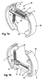
- an adjusting device 14 arranged between two brake shoes 1, 2 for a drum brake of a motor vehicle is shown.
- the adjusting device 14 is usually accommodated together with the brake shoes 1, 2 in the interior of a brake drum, which, however, is not shown in the figures to illustrate the features according to the invention.
- the basic arrangement of the adjusting device 14 with the two brake shoes 1, 2 within the brake drum or drum brake does not need to be discussed at this point, however, since it is known, for example, from DE 26 44 575 A1 and also for those shown in the figures Execution was taken over.
- the aforementioned brake shoes 1, 2 have in the usual way a T-shaped cross section with a flange facing the brake drum (not shown) on which the respective friction lining 15 is fastened.
- the first two ends 16 of the two brake shoes 1, 2 are usually supported on an abutment or support bearing, ie for drum brakes of the simplex type.
- an actuating device is provided between second ends 17 of the brake shoes 1, 2. This is often designed as a hydraulic wheel cylinder and serves to initiate the application force supplied by the service brake system in the event of service braking.
- the brake shoes 1, 2 pressed against the brake drum by means of the actuating device are released from the brake drum with the aid of at least one tension spring 10, 11 and moved towards one another until they come to rest on a pressure strut 4.
- This pressure strut 4 is arranged adjacent to the actuating device and extends between the two brake shoes 1, 2.
- the pressure strut 4 lies due to the action of the first tension spring 10 on the second brake shoe 2 via a brake lever 3 on.
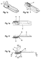
- 1 may appear on this first brake shoe Wedge bearing 8 can be attached, which as an abutment for the Control wedge 7 is used, as is basically the case in DE-OS 26 44 575 is described.
- the wedge bearing 8 is preferred executed as a sheet metal component.
- Locking element 5 is provided, which as the strut 4th sliding carriage is executed and over a Switch pin 6 is mounted on the pressure strut 4. Is to the switching pin 6 is fastened in an opening of the locking element 5 and at the same time in an elongated hole 19 of the strut 4 added.
- the locking element 5 is in turn a on the first brake shoe 1 hooked locking spring 9 opposite the control wedge 7 biased.
- a the blocking element 5 interacting temperature-dependent Switching device 18 is provided. By means of the switching device 18 can the locking element 5 with respect to the pressure strut 4th can be locked by moving the switching pin 6.
- the aforementioned adjusting wedge 7 thus extends with its associated wedge surfaces in an opening between the slidable on the strut 4 mounted locking element 5 and the wedge bearing 8 or the first brake shoe 1. It points between its wedge surfaces at a wedge angle and is below Taking into account the friction values between the adjusting wedge 7 and Dimension locking element 5 or first brake shoe 1 so that Self-locking occurs, as is the case in the aforementioned publication 26 44 575 is described in detail.
- the adjusting wedge 7 is opposed by means of a wedge spring 13 the first brake shoe 1 biased so that it strives to move in the direction of the wedge spring 13.
- the wedge 7 Without friction lining wear, d. H. without re-adjustment the wedge 7 is in balance and keeps its position at, so that it in the opening between the locking element 5 and first brake shoe 1 or wedge bearing 8 do not penetrate further can.
- an additionally provided Brake lever 3 is operated, which at one Parking brake actuation not shown pivoted acts.
- the brake lever 3 is pivotable on the second Brake shoe 2 mounted and also supports in particular with a pivoting movement on the pressure strut 4 and can thus the actuating force via the pressure strut 4 or transfer the setting wedge 7 to the first brake shoe.
- the Brake shoes are spread radially as described above and brought into contact with the brake drum, not shown.
- the locking element 5 is as a sled-shaped component slidable on the pressure strut 4 stored.
- the blocking element 5 is through a through opening attached to a switching pin 6, which in a Elongated hole 19 of the strut 4 is slidably received.
- the locking element 5 is molded on Tab 20 in an opening 21 of the strut 4 during Shift led.
- the temperature-dependent switching device 18 further includes at least one temperature sensitive Thermocouple 12, 12 ', 22, 22' with the switching pin 6 interacts.
- thermocouples 12, 12 ', 22, 22' are provided, which are arranged on opposite sides of the pressure strut 4 are and the switching pin 6 each with one in the direction can act on the bolt axis 23 acting force.
- thermocouple or a package of several thermocouples against the bias of an opposite spring takes effect.
- the thermocouple 12, 12 ', 22, 22' is there from a bimetal material or from a material with similar temperature-dependent material properties, z. B. from a shape memory alloy. All of these materials possess the property with temperature changes their change geometric appearance. Is the temperature fluctuation ended and reached the initial temperature again, the component also takes one of the above Materials back to their original form. This Material property is now used to implement the thermal Switching function used.
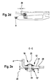
- the switching device 18 has depending on the current Temperature state two switch positions in the Figures 2a-c and 2d-f are shown.
- the switching pin 6 is in one Elongated hole section 19 'with a larger diameter.
- these Elongated hole section 19 ' protrudes the switching pin 6 with a corresponding Shift pin section 24 with a suitable diameter into it.
- the switching pin 6 is in its position fixed within the slot 19. The same applies to the locking element 5 attached to the switching pin 6, the opposite the strut 4 is locked.
- the Switch pin 6 by means of two thermocouples acting in opposite directions 12, 12 'held in its locked switch position.
- the Thermocouples 12, 12 ' are preferably disc springs or disc spring assemblies made of bimetal or a material with similar material properties.
- a disc spring assembly 12 At normal temperature or below a specified trigger temperature is a disc spring assembly 12 in the spread position during the other plate spring assembly 12 'lies on a block.
- the blocking element 5 acts like an integral part of the strut 4, so that a Adjustment or wedge displacement is permitted, if by strut movement due to friction lining wear the setting wedge 7 is released and as described above increasing its effective for re-enactment Wedge surface can be adjusted.
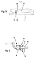
- thermocouples 12, 12 ' In the event of strong warming or exceeding a specified one Tripping temperature of the switching device 18 becomes the second Switched position according to FIG. 2d-f.
- the first thermocouple is 12 on block and the other thermocouple 12 'accordingly in spread position.
- the switching pin 6 comes with his thickened shift pin portion 24 out of engagement with the associated slot section 19 'and is thus in the slot 19 freely movable.
- This also turns the blocking element 5 released so that it moves to the blocking stroke 26 can.
- the setting wedge 7 is now located in equilibrium between the force of the wedge spring 13 and the force of the locking element 5 by the locking tension spring 9.
- the locking element 5 remains independent of Operating state of the drum brake in contact with the setting wedge 7, so that an adjusting wedge displacement and thus a pure thermally induced readjustment is omitted.
- FIG 3 shows a further embodiment of the switching device 18 in its first switching position with an alternative variant of the thermocouple or thermocouples 22, 22 '.
- the oppositely effective thermocouples 22, 22 ' are as sheet metal clips 22, 22 'made of a bimetal material or a analog acting material, e.g. B. a shape memory alloy, educated.
- the thermocouples 12, 12 ', 22, 22' can be designed to be very diverse the respective requirements, in particular with regard to the adapt necessary switching forces.
- the temperature-dependent switching device 18 an unwanted adjustment at very high temperatures prevented within the drum brake.
- the arrangement enables a separation of functions between readjustment and locking function, so that the locking mechanism for the adjusting device 14 also during the Actuation of the drum brake is effective.
Landscapes
- Engineering & Computer Science (AREA)
- General Engineering & Computer Science (AREA)
- Mechanical Engineering (AREA)
- Braking Arrangements (AREA)
Applications Claiming Priority (2)
| Application Number | Priority Date | Filing Date | Title |
|---|---|---|---|
| DE10035456 | 2000-07-19 | ||
| DE10035456A DE10035456A1 (de) | 2000-07-19 | 2000-07-19 | Nachstellvorrichtung für eine Trommelbremse mit temperaturabhängiger Schaltvorrichtung |
Publications (2)
| Publication Number | Publication Date |
|---|---|
| EP1174635A1 true EP1174635A1 (fr) | 2002-01-23 |
| EP1174635B1 EP1174635B1 (fr) | 2003-08-06 |
Family
ID=7649673
Family Applications (1)
| Application Number | Title | Priority Date | Filing Date |
|---|---|---|---|
| EP01114961A Expired - Lifetime EP1174635B1 (fr) | 2000-07-19 | 2001-06-20 | Dispositif de réglage pour frein à tambour avec un dispositif de commutation dépendante de la température |
Country Status (3)
| Country | Link |
|---|---|
| EP (1) | EP1174635B1 (fr) |
| CN (1) | CN1214194C (fr) |
| DE (2) | DE10035456A1 (fr) |
Families Citing this family (3)
| Publication number | Priority date | Publication date | Assignee | Title |
|---|---|---|---|---|
| CN111169454B (zh) * | 2018-11-13 | 2021-07-20 | 宝沃汽车(中国)有限公司 | 车辆制动辅助方法、装置、控制器及车辆 |
| DE102019213756A1 (de) | 2019-01-11 | 2020-07-16 | Continental Teves Ag & Co. Ohg | Topfförmiger Verbundbremsrotor für Kraftfahrzeuge |
| CN110486397A (zh) * | 2019-09-12 | 2019-11-22 | 江西制造职业技术学院 | 一种基于温控形状记忆合金弹簧的鼓式刹车冷却装置 |
Citations (3)
| Publication number | Priority date | Publication date | Assignee | Title |
|---|---|---|---|---|
| US2740499A (en) * | 1953-05-26 | 1956-04-03 | George C Dear | Self-adjusting means for internal expanding brakes |
| DE2644575A1 (de) * | 1976-10-02 | 1978-04-06 | Volkswagenwerk Ag | Innenbacken-trommelbremse mit einer selbsttaetigen mechanischen nachstellvorrichtung |
| US4809826A (en) * | 1987-01-29 | 1989-03-07 | Bendix France | Drum brake with automatic adjustment |
Family Cites Families (3)
| Publication number | Priority date | Publication date | Assignee | Title |
|---|---|---|---|---|
| DE3248015A1 (de) * | 1982-12-24 | 1984-06-28 | Alfred Teves Gmbh, 6000 Frankfurt | Vorrichtung zur nachstellung von bremsbelaegen |
| FR2727732A1 (fr) * | 1994-12-02 | 1996-06-07 | Alliedsignal Europ Services | Frein a tambour utilisant un rattrapage automatique a came a action selective |
| DE19910491A1 (de) * | 1999-03-10 | 2000-09-14 | Continental Teves Ag & Co Ohg | Keilnachstellung mit Thermo-Clip |
-
2000
- 2000-07-19 DE DE10035456A patent/DE10035456A1/de not_active Withdrawn
-
2001
- 2001-06-20 EP EP01114961A patent/EP1174635B1/fr not_active Expired - Lifetime
- 2001-06-20 DE DE50100457T patent/DE50100457D1/de not_active Expired - Lifetime
- 2001-07-18 CN CNB011232366A patent/CN1214194C/zh not_active Expired - Fee Related
Patent Citations (3)
| Publication number | Priority date | Publication date | Assignee | Title |
|---|---|---|---|---|
| US2740499A (en) * | 1953-05-26 | 1956-04-03 | George C Dear | Self-adjusting means for internal expanding brakes |
| DE2644575A1 (de) * | 1976-10-02 | 1978-04-06 | Volkswagenwerk Ag | Innenbacken-trommelbremse mit einer selbsttaetigen mechanischen nachstellvorrichtung |
| US4809826A (en) * | 1987-01-29 | 1989-03-07 | Bendix France | Drum brake with automatic adjustment |
Also Published As
| Publication number | Publication date |
|---|---|
| CN1334211A (zh) | 2002-02-06 |
| DE50100457D1 (de) | 2003-09-11 |
| EP1174635B1 (fr) | 2003-08-06 |
| DE10035456A1 (de) | 2002-01-31 |
| CN1214194C (zh) | 2005-08-10 |
Similar Documents
| Publication | Publication Date | Title |
|---|---|---|
| DE3019223C2 (fr) | ||
| DE3019214C2 (fr) | ||
| EP2644926B1 (fr) | Frein à disque avec dispositif de rappel et garniture de frein correspondante | |
| EP0195081B1 (fr) | Dispositif auto-regulateur pour freins | |
| DE69030588T2 (de) | Automatische Nachstellvorrichtung für Trommelbremse | |
| EP1565668B1 (fr) | Frein a disque equipe d'un dispositif d'ajustage, en particulier pour un vehicule utilitaire | |
| EP1174635B1 (fr) | Dispositif de réglage pour frein à tambour avec un dispositif de commutation dépendante de la température | |
| DE3218788C2 (fr) | ||
| DE3148072C2 (fr) | ||
| EP0575825B1 (fr) | Dispositif de rajustage pour un frein, en particulier pour un frein à tambour | |
| DE60031361T2 (de) | Automatischer spielnachsteller für kraftfahrzeugtrommelbremse | |
| DE3248015C2 (fr) | ||
| DE2943596C2 (de) | Temperaturabhängiges Spreizglied für eine Innenbackentrommelbremse | |
| DE3139173C2 (fr) | ||
| EP0869292B1 (fr) | Dispositif automatique de rattrapage de jeu pour un frein à tambour | |
| DE202007007022U1 (de) | Innenbackenbremse mit automatischer Nachstelleinrichtung für das Bremsbackenlüftspiel | |
| DE102009036222B4 (de) | Innenbackenbremse mit thermisch geregelter Nachstelleinrichtung für das Bremsbackenlüftspiel | |
| DE69307490T2 (de) | Automatische nachstelleinrichtung für bremsen | |
| EP1225364B1 (fr) | Dispositif de rattrapage d'usure pour frein à tambour | |
| EP0123730B1 (fr) | Dispositif pour le rajustage des garnitures de frein | |
| DE3920764C2 (de) | Selbsttätige Nachstellvorrichtung für eine Duo-Servo-Trommelbremse | |
| DE19858745A1 (de) | Trommelbremse mit thermischer Nachstellungsbegrenzung | |
| DE10325957B4 (de) | Bremsbaugruppe mit der Thermoregulierung des Spieles | |
| EP0584810B1 (fr) | Dispositif de rajustage et de centrage sur l'élément poussé d'un servo-frein à tambour | |
| DE19910491A1 (de) | Keilnachstellung mit Thermo-Clip |
Legal Events
| Date | Code | Title | Description |
|---|---|---|---|
| PUAI | Public reference made under article 153(3) epc to a published international application that has entered the european phase |
Free format text: ORIGINAL CODE: 0009012 |
|
| AK | Designated contracting states |
Kind code of ref document: A1 Designated state(s): AT BE CH CY DE DK ES FI FR GB GR IE IT LI LU MC NL PT SE TR Kind code of ref document: A1 Designated state(s): DE FR IT |
|
| AX | Request for extension of the european patent |
Free format text: AL;LT;LV;MK;RO;SI |
|
| 17P | Request for examination filed |
Effective date: 20020723 |
|
| AKX | Designation fees paid |
Free format text: DE FR IT |
|
| GRAH | Despatch of communication of intention to grant a patent |
Free format text: ORIGINAL CODE: EPIDOS IGRA |
|
| GRAH | Despatch of communication of intention to grant a patent |
Free format text: ORIGINAL CODE: EPIDOS IGRA |
|
| GRAA | (expected) grant |
Free format text: ORIGINAL CODE: 0009210 |
|
| AK | Designated contracting states |
Designated state(s): DE FR IT |
|
| REG | Reference to a national code |
Ref country code: IE Ref legal event code: FG4D Free format text: GERMAN |
|
| REF | Corresponds to: |
Ref document number: 50100457 Country of ref document: DE Date of ref document: 20030911 Kind code of ref document: P |
|
| REG | Reference to a national code |
Ref country code: IE Ref legal event code: FD4D |
|
| ET | Fr: translation filed | ||
| PLBE | No opposition filed within time limit |
Free format text: ORIGINAL CODE: 0009261 |
|
| STAA | Information on the status of an ep patent application or granted ep patent |
Free format text: STATUS: NO OPPOSITION FILED WITHIN TIME LIMIT |
|
| 26N | No opposition filed |
Effective date: 20040507 |
|
| PGFP | Annual fee paid to national office [announced via postgrant information from national office to epo] |
Ref country code: FR Payment date: 20050616 Year of fee payment: 5 |
|
| PGFP | Annual fee paid to national office [announced via postgrant information from national office to epo] |
Ref country code: IT Payment date: 20060630 Year of fee payment: 6 |
|
| REG | Reference to a national code |
Ref country code: FR Ref legal event code: ST Effective date: 20070228 |
|
| PG25 | Lapsed in a contracting state [announced via postgrant information from national office to epo] |
Ref country code: FR Free format text: LAPSE BECAUSE OF NON-PAYMENT OF DUE FEES Effective date: 20060630 |
|
| PG25 | Lapsed in a contracting state [announced via postgrant information from national office to epo] |
Ref country code: IT Free format text: LAPSE BECAUSE OF NON-PAYMENT OF DUE FEES Effective date: 20070620 |
|
| PGFP | Annual fee paid to national office [announced via postgrant information from national office to epo] |
Ref country code: DE Payment date: 20130630 Year of fee payment: 13 |
|
| REG | Reference to a national code |
Ref country code: DE Ref legal event code: R119 Ref document number: 50100457 Country of ref document: DE |
|
| REG | Reference to a national code |
Ref country code: DE Ref legal event code: R119 Ref document number: 50100457 Country of ref document: DE Effective date: 20150101 |
|
| PG25 | Lapsed in a contracting state [announced via postgrant information from national office to epo] |
Ref country code: DE Free format text: LAPSE BECAUSE OF NON-PAYMENT OF DUE FEES Effective date: 20150101 |