EP1174599A1 - Filter system for an exhaust gas cleaning device - Google Patents
Filter system for an exhaust gas cleaning device Download PDFInfo
- Publication number
- EP1174599A1 EP1174599A1 EP01117067A EP01117067A EP1174599A1 EP 1174599 A1 EP1174599 A1 EP 1174599A1 EP 01117067 A EP01117067 A EP 01117067A EP 01117067 A EP01117067 A EP 01117067A EP 1174599 A1 EP1174599 A1 EP 1174599A1
- Authority
- EP
- European Patent Office
- Prior art keywords
- filter
- foils
- arrangement according
- filter arrangement
- filter plate
- Prior art date
- Legal status (The legal status is an assumption and is not a legal conclusion. Google has not performed a legal analysis and makes no representation as to the accuracy of the status listed.)
- Granted
Links
Images


Classifications
-
- B—PERFORMING OPERATIONS; TRANSPORTING
- B01—PHYSICAL OR CHEMICAL PROCESSES OR APPARATUS IN GENERAL
- B01D—SEPARATION
- B01D53/00—Separation of gases or vapours; Recovering vapours of volatile solvents from gases; Chemical or biological purification of waste gases, e.g. engine exhaust gases, smoke, fumes, flue gases, aerosols
- B01D53/34—Chemical or biological purification of waste gases
- B01D53/92—Chemical or biological purification of waste gases of engine exhaust gases
- B01D53/94—Chemical or biological purification of waste gases of engine exhaust gases by catalytic processes
- B01D53/9445—Simultaneously removing carbon monoxide, hydrocarbons or nitrogen oxides making use of three-way catalysts [TWC] or four-way-catalysts [FWC]
- B01D53/9454—Simultaneously removing carbon monoxide, hydrocarbons or nitrogen oxides making use of three-way catalysts [TWC] or four-way-catalysts [FWC] characterised by a specific device
-
- B—PERFORMING OPERATIONS; TRANSPORTING
- B01—PHYSICAL OR CHEMICAL PROCESSES OR APPARATUS IN GENERAL
- B01D—SEPARATION
- B01D53/00—Separation of gases or vapours; Recovering vapours of volatile solvents from gases; Chemical or biological purification of waste gases, e.g. engine exhaust gases, smoke, fumes, flue gases, aerosols
- B01D53/34—Chemical or biological purification of waste gases
- B01D53/92—Chemical or biological purification of waste gases of engine exhaust gases
- B01D53/94—Chemical or biological purification of waste gases of engine exhaust gases by catalytic processes
- B01D53/9404—Removing only nitrogen compounds
- B01D53/9409—Nitrogen oxides
- B01D53/9431—Processes characterised by a specific device
-
- F—MECHANICAL ENGINEERING; LIGHTING; HEATING; WEAPONS; BLASTING
- F01—MACHINES OR ENGINES IN GENERAL; ENGINE PLANTS IN GENERAL; STEAM ENGINES
- F01N—GAS-FLOW SILENCERS OR EXHAUST APPARATUS FOR MACHINES OR ENGINES IN GENERAL; GAS-FLOW SILENCERS OR EXHAUST APPARATUS FOR INTERNAL COMBUSTION ENGINES
- F01N3/00—Exhaust or silencing apparatus having means for purifying, rendering innocuous, or otherwise treating exhaust
- F01N3/02—Exhaust or silencing apparatus having means for purifying, rendering innocuous, or otherwise treating exhaust for cooling, or for removing solid constituents of, exhaust
- F01N3/021—Exhaust or silencing apparatus having means for purifying, rendering innocuous, or otherwise treating exhaust for cooling, or for removing solid constituents of, exhaust by means of filters
- F01N3/0217—Exhaust or silencing apparatus having means for purifying, rendering innocuous, or otherwise treating exhaust for cooling, or for removing solid constituents of, exhaust by means of filters the filtering elements having the form of hollow cylindrical bodies
-
- F—MECHANICAL ENGINEERING; LIGHTING; HEATING; WEAPONS; BLASTING
- F01—MACHINES OR ENGINES IN GENERAL; ENGINE PLANTS IN GENERAL; STEAM ENGINES
- F01N—GAS-FLOW SILENCERS OR EXHAUST APPARATUS FOR MACHINES OR ENGINES IN GENERAL; GAS-FLOW SILENCERS OR EXHAUST APPARATUS FOR INTERNAL COMBUSTION ENGINES
- F01N3/00—Exhaust or silencing apparatus having means for purifying, rendering innocuous, or otherwise treating exhaust
- F01N3/02—Exhaust or silencing apparatus having means for purifying, rendering innocuous, or otherwise treating exhaust for cooling, or for removing solid constituents of, exhaust
- F01N3/021—Exhaust or silencing apparatus having means for purifying, rendering innocuous, or otherwise treating exhaust for cooling, or for removing solid constituents of, exhaust by means of filters
- F01N3/023—Exhaust or silencing apparatus having means for purifying, rendering innocuous, or otherwise treating exhaust for cooling, or for removing solid constituents of, exhaust by means of filters using means for regenerating the filters, e.g. by burning trapped particles
- F01N3/029—Exhaust or silencing apparatus having means for purifying, rendering innocuous, or otherwise treating exhaust for cooling, or for removing solid constituents of, exhaust by means of filters using means for regenerating the filters, e.g. by burning trapped particles by adding non-fuel substances to exhaust
-
- F—MECHANICAL ENGINEERING; LIGHTING; HEATING; WEAPONS; BLASTING
- F01—MACHINES OR ENGINES IN GENERAL; ENGINE PLANTS IN GENERAL; STEAM ENGINES
- F01N—GAS-FLOW SILENCERS OR EXHAUST APPARATUS FOR MACHINES OR ENGINES IN GENERAL; GAS-FLOW SILENCERS OR EXHAUST APPARATUS FOR INTERNAL COMBUSTION ENGINES
- F01N3/00—Exhaust or silencing apparatus having means for purifying, rendering innocuous, or otherwise treating exhaust
- F01N3/02—Exhaust or silencing apparatus having means for purifying, rendering innocuous, or otherwise treating exhaust for cooling, or for removing solid constituents of, exhaust
- F01N3/021—Exhaust or silencing apparatus having means for purifying, rendering innocuous, or otherwise treating exhaust for cooling, or for removing solid constituents of, exhaust by means of filters
- F01N3/033—Exhaust or silencing apparatus having means for purifying, rendering innocuous, or otherwise treating exhaust for cooling, or for removing solid constituents of, exhaust by means of filters in combination with other devices
- F01N3/035—Exhaust or silencing apparatus having means for purifying, rendering innocuous, or otherwise treating exhaust for cooling, or for removing solid constituents of, exhaust by means of filters in combination with other devices with catalytic reactors, e.g. catalysed diesel particulate filters
-
- F—MECHANICAL ENGINEERING; LIGHTING; HEATING; WEAPONS; BLASTING
- F01—MACHINES OR ENGINES IN GENERAL; ENGINE PLANTS IN GENERAL; STEAM ENGINES
- F01N—GAS-FLOW SILENCERS OR EXHAUST APPARATUS FOR MACHINES OR ENGINES IN GENERAL; GAS-FLOW SILENCERS OR EXHAUST APPARATUS FOR INTERNAL COMBUSTION ENGINES
- F01N3/00—Exhaust or silencing apparatus having means for purifying, rendering innocuous, or otherwise treating exhaust
- F01N3/08—Exhaust or silencing apparatus having means for purifying, rendering innocuous, or otherwise treating exhaust for rendering innocuous
- F01N3/10—Exhaust or silencing apparatus having means for purifying, rendering innocuous, or otherwise treating exhaust for rendering innocuous by thermal or catalytic conversion of noxious components of exhaust
- F01N3/18—Exhaust or silencing apparatus having means for purifying, rendering innocuous, or otherwise treating exhaust for rendering innocuous by thermal or catalytic conversion of noxious components of exhaust characterised by methods of operation; Control
- F01N3/20—Exhaust or silencing apparatus having means for purifying, rendering innocuous, or otherwise treating exhaust for rendering innocuous by thermal or catalytic conversion of noxious components of exhaust characterised by methods of operation; Control specially adapted for catalytic conversion ; Methods of operation or control of catalytic converters
- F01N3/206—Adding periodically or continuously substances to exhaust gases for promoting purification, e.g. catalytic material in liquid form, NOx reducing agents
-
- F—MECHANICAL ENGINEERING; LIGHTING; HEATING; WEAPONS; BLASTING
- F01—MACHINES OR ENGINES IN GENERAL; ENGINE PLANTS IN GENERAL; STEAM ENGINES
- F01N—GAS-FLOW SILENCERS OR EXHAUST APPARATUS FOR MACHINES OR ENGINES IN GENERAL; GAS-FLOW SILENCERS OR EXHAUST APPARATUS FOR INTERNAL COMBUSTION ENGINES
- F01N2240/00—Combination or association of two or more different exhaust treating devices, or of at least one such device with an auxiliary device, not covered by indexing codes F01N2230/00 or F01N2250/00, one of the devices being
- F01N2240/20—Combination or association of two or more different exhaust treating devices, or of at least one such device with an auxiliary device, not covered by indexing codes F01N2230/00 or F01N2250/00, one of the devices being a flow director or deflector
-
- F—MECHANICAL ENGINEERING; LIGHTING; HEATING; WEAPONS; BLASTING
- F01—MACHINES OR ENGINES IN GENERAL; ENGINE PLANTS IN GENERAL; STEAM ENGINES
- F01N—GAS-FLOW SILENCERS OR EXHAUST APPARATUS FOR MACHINES OR ENGINES IN GENERAL; GAS-FLOW SILENCERS OR EXHAUST APPARATUS FOR INTERNAL COMBUSTION ENGINES
- F01N2250/00—Combinations of different methods of purification
- F01N2250/02—Combinations of different methods of purification filtering and catalytic conversion
-
- F—MECHANICAL ENGINEERING; LIGHTING; HEATING; WEAPONS; BLASTING
- F01—MACHINES OR ENGINES IN GENERAL; ENGINE PLANTS IN GENERAL; STEAM ENGINES
- F01N—GAS-FLOW SILENCERS OR EXHAUST APPARATUS FOR MACHINES OR ENGINES IN GENERAL; GAS-FLOW SILENCERS OR EXHAUST APPARATUS FOR INTERNAL COMBUSTION ENGINES
- F01N2430/00—Influencing exhaust purification, e.g. starting of catalytic reaction, filter regeneration, or the like, by controlling engine operating characteristics
- F01N2430/04—Influencing exhaust purification, e.g. starting of catalytic reaction, filter regeneration, or the like, by controlling engine operating characteristics by adding non-fuel substances to combustion air or fuel, e.g. additives
-
- F—MECHANICAL ENGINEERING; LIGHTING; HEATING; WEAPONS; BLASTING
- F01—MACHINES OR ENGINES IN GENERAL; ENGINE PLANTS IN GENERAL; STEAM ENGINES
- F01N—GAS-FLOW SILENCERS OR EXHAUST APPARATUS FOR MACHINES OR ENGINES IN GENERAL; GAS-FLOW SILENCERS OR EXHAUST APPARATUS FOR INTERNAL COMBUSTION ENGINES
- F01N2610/00—Adding substances to exhaust gases
- F01N2610/02—Adding substances to exhaust gases the substance being ammonia or urea
-
- Y—GENERAL TAGGING OF NEW TECHNOLOGICAL DEVELOPMENTS; GENERAL TAGGING OF CROSS-SECTIONAL TECHNOLOGIES SPANNING OVER SEVERAL SECTIONS OF THE IPC; TECHNICAL SUBJECTS COVERED BY FORMER USPC CROSS-REFERENCE ART COLLECTIONS [XRACs] AND DIGESTS
- Y02—TECHNOLOGIES OR APPLICATIONS FOR MITIGATION OR ADAPTATION AGAINST CLIMATE CHANGE
- Y02A—TECHNOLOGIES FOR ADAPTATION TO CLIMATE CHANGE
- Y02A50/00—TECHNOLOGIES FOR ADAPTATION TO CLIMATE CHANGE in human health protection, e.g. against extreme weather
- Y02A50/20—Air quality improvement or preservation, e.g. vehicle emission control or emission reduction by using catalytic converters
-
- Y—GENERAL TAGGING OF NEW TECHNOLOGICAL DEVELOPMENTS; GENERAL TAGGING OF CROSS-SECTIONAL TECHNOLOGIES SPANNING OVER SEVERAL SECTIONS OF THE IPC; TECHNICAL SUBJECTS COVERED BY FORMER USPC CROSS-REFERENCE ART COLLECTIONS [XRACs] AND DIGESTS
- Y02—TECHNOLOGIES OR APPLICATIONS FOR MITIGATION OR ADAPTATION AGAINST CLIMATE CHANGE
- Y02T—CLIMATE CHANGE MITIGATION TECHNOLOGIES RELATED TO TRANSPORTATION
- Y02T10/00—Road transport of goods or passengers
- Y02T10/10—Internal combustion engine [ICE] based vehicles
- Y02T10/12—Improving ICE efficiencies
-
- Y—GENERAL TAGGING OF NEW TECHNOLOGICAL DEVELOPMENTS; GENERAL TAGGING OF CROSS-SECTIONAL TECHNOLOGIES SPANNING OVER SEVERAL SECTIONS OF THE IPC; TECHNICAL SUBJECTS COVERED BY FORMER USPC CROSS-REFERENCE ART COLLECTIONS [XRACs] AND DIGESTS
- Y10—TECHNICAL SUBJECTS COVERED BY FORMER USPC
- Y10S—TECHNICAL SUBJECTS COVERED BY FORMER USPC CROSS-REFERENCE ART COLLECTIONS [XRACs] AND DIGESTS
- Y10S55/00—Gas separation
- Y10S55/30—Exhaust treatment
Definitions
- the invention relates to a filter arrangement for an exhaust gas cleaning system an internal combustion engine, in particular an internal combustion engine a motor vehicle, in the filter plate elements with pairwise formation of filter bags on their outer circumference and on their inner circumference are interconnected.
- Such a filter arrangement is known from DE 198 10 738 C1.
- the Known filter arrangement is for the exhaust gas purification system of a motor vehicle internal combustion engine provided as a particle filter and serves in particular for cleaning soot from the exhaust gas of a diesel engine.
- the filter arrangement is by porous filter plates in the form of sintered metal plate rings built up with the formation of alternating external and the inner filter bags welded together to form a filter package become.
- the filter arrangement is catalytically inactive.
- Such Filter arrangement can with an oxidation catalyst and / or a Nitrogen oxide reduction catalyst can be combined, the required Increase the installation space for the exhaust gas cleaning system.
- the object of the invention is a filter arrangement of the aforementioned Type to create that, in addition to filtering soot particles, also soot oxidation and / or the reduction of nitrogen oxides.
- the filter bags outside and / or catalyst means are assigned on the inside.
- Solution are in the filter arrangement in addition to the filter effect, in particular in the form of a particle filter, still catalyst functions integrated so that the filter arrangement is multifunctional is.
- the additional catalyst functions are in contrast to State of the art achieved in the solution according to the invention without that Increase the volume or space for the exhaust gas cleaning system to have to. This makes it an extremely space-saving yet functional solution created.
- the filter plate elements are preferred designed like a plate and provided with a central passage, so that they have a ring shape.
- catalytic agents are catalytic active slides provided.
- the foils are preferably analogous to the filter plate elements designed rotationally symmetrical to the filter center longitudinal axis. Neither foils nor filter plate elements are basically on the rotationally symmetrical design is limited. In the same way you can they can also be angular or shaped in another suitable manner.
- the films are on the outside or internal vertices of the filter bags with the filter plate elements connected and protrude freely into the outside or inside Filter bags, in particular radially to a filter center axis.
- the foils have a stiffening structure Mistake. This prevents the films from operating the filter arrangement through the exhaust gas flow and in particular begin to flutter through appropriate pressure pulses of the exhaust gas flow.
- the respective film can in particular be used as a stiffening structure be stamped accordingly.
- the films are by means of proppants the filter bags fixed in their radial alignment.
- the filter plate elements provide appropriate support for the foils achieved by providing the filter plate elements with suitable support means are.
- the filter plate rings can in particular be used as a support be provided with a nub structure that is disc-shaped or disc-shaped Foils over their entire area or over part of the Support the surface point by point.
- At least part of the films actively catalyzed by oxidation is advantageous set at the inside vertices of the filter bags to achieve the corresponding catalyst function on the inlet side. hereby it is possible to oxidize soot occurring in the exhaust gas, which in particular is advantageous for diesel engines.
- the foils also at the outer vertices with the filter plate elements be connected so that they protrude inwards and thus from Exhaust gas flowing inward from the outside is attached on the outlet side. This does not promote soot oxidation; however, it will Oxidation of HC or CO in the exhaust gas is improved because it is on the outlet side no deposits of soot or other solid particles on the We therefore have an improved activity of the catalyst effect is achievable.
- the films active with a catalyst material that supports nitrogen oxide reduction coated can both on the inlet and outlet side of the exhaust gas flow and thus both in the outwardly open as well as in the inwardly open filter pockets be positioned.
- the foils are dosing agents for the supply of a reducing agent, in particular ammonia, assigned.
- Flow channels in the filter arrangement are particularly suitable as dosing means integrated, which the injection of ammonia at a suitable point guarantee.
- channel sections of the dosing means by embossing the filter plate elements accordingly integrated into this.
- the metering channels are at least partially included in the filter plate elements. This is a special one easy to manufacture arrangement that does not require any additional components.
- the filter arrangements according to FIGS. 1 to 6 are for exhaust gas cleaning systems of motor vehicle internal combustion engines, in particular of diesel engines, intended. All filter arrangements according to FIGS. 1 to 6 each have a filter housing in which a packet of annular Filter plates 2 is arranged. Both the filter housing 1 and that Package of filter plate rings 2 is rotationally symmetrical to a central longitudinal axis M designed the filter arrangement.
- the filter housing 1 has one inlet E for the exhaust gas flow to be cleaned and one on the opposite End of the filter housing 1 provided outlet A for the cleaned exhaust gas flow.
- the exhaust gas flow is in all embodiments 1 to 5 by corresponding arrows in their course is shown optically, the corresponding arrows only represent symbolically certain partial flows. However, the expert is clear that all filter plate rings 2 within the filter housing 1 in are flowed through accordingly.
- the filter plate rings 2 are porous to the flow of the To ensure exhaust gas flow.
- the filter plate rings 2 designed as sintered metal plates and plate-like executed.
- the filter plate rings 2 are each in pairs put together that between two adjacent filter plate rings result in external and internal filter bags.
- the filter plate rings 2 are both in the area of the outer vertices 3 of the filter bags, d. H. their outer edges, as well as in the area their inner vertices 4, d. H. in the area of their inner edges, all around firmly connected, preferably welded together.
- the filter plate rings positioned at the end in the area of the outlet A. 2 are with their inner vertices, i. H. their inner Edges, firmly connected to the inside of the filter housing 1, in particular welded.
- Filter plate ring 2 is in the area of its inner passage closed by a baffle plate 5, so that the exhaust gas flow, which in the filter housing 1 enters, according to the arrow representation radially to the central longitudinal axis M is diverted to all sides.
- the exhaust gas flow then penetrates from the outside all filter plate rings 2 towards the inside, as shown by the arrow. From the inside of the package from filter plate rings, the exhaust gas flow then becomes outlet A directed.
- the porous design of the filter plate rings 2 is radial Exhaust gas flow flowing through the filter plate rings 2 from outside to inside exerted a filtering effect through the corresponding Solid particles within the exhaust gas flow, such as soot in particular the outer walls of the filter plate rings 2 and thus in the area of Store external filter bags.
- the foils 6, 6a, 6b are thus only in the area of the respective apex 3, 4 firmly with the filter plate rings 2 connected and otherwise project freely into the respective Filter bag.
- the foils 6, 6a, 6b can be shown in FIG Way with a stiffening structure in the form of ribs, Webs or embossing can be provided, whereby the rigidity of the respective Slides 6, 6a, 6b is increased.
- the Filter plate rings 2 in a manner also not shown in the knob structures protruding into the respective filter pockets, the films 6, 6a, 6b at least partially point-like from both sides support. The knobs are aligned at right angles to the foils 6 and attack from both sides on each film 6, 6a, 6b.
- the filter arrangements 1 according to FIGS. 1 and 2 have oxidation catalytic actively coated films 6a, 6b, which in the exemplary embodiment 1 on the inside and thus on the outlet side of the filter plate rings 2 and in the embodiment according to FIG. 2 on the outside and thus on the inlet side the filter plate rings 2 are arranged.
- the exit side 1 is in particular an oxidation of HC and CO achieved in the exhaust gas stream, the surface of the films 6a in their Activity is not affected by deposits. Because these deposits are outside, d. H. on the exhaust gas inlet side, on the filter plate rings 2 intercepted.
- the catalyst surface is doubled, by in the area of all filter bags, d. H. both one and one corresponding catalytic oxidation on the outlet side of the filter plate rings 2 active foils 6a, 6b are arranged. Doing so with the outside Foils 6b functions and advantages of the embodiment according to FIG. 2 and the inner foils 6a advantages and functions of the embodiment 1 reached.
- the filter arrangement in the Filter housing 1 catalytically active films 6c, which are used for reduction of nitrogen oxides.
- the catalytic in terms of nitrogen oxide reduction 4 and 5 are active with the reference numerals 6c provided the difference to the oxidation-catalytically active Present slides 6, 6a, 6b.
- These foils 6c protrude into the interior Filter bags in and are thus arranged on the outlet side.
- the corresponding reducing agent Feed in the present case ammonia
- dosing agents for the foils 6c 7, 8 assigned which allow injection of the ammonia. For this are three evenly distributed over the circumference, parallel to the central longitudinal axis M extending channel sections 7 are provided (Fig.
- each film 6c with radially protruding branches in the form are provided by nozzle channels 8.
- the correspondingly catalytically active Films can also be arranged on the inlet side of the filter plate rings 2. 5 can of course double the number of foils be provided to double the catalytically active area.
- the films which are catalytically active with respect to nitrogen oxide reduction with oxidation catalytic to combine active foils and exterior and / or to provide internal arrangements of these foils in the area of the filter bags.
Abstract
Description
Die Erfindung betrifft eine Filteranordnung für eine Abgasreinigungsanlage einer Verbrennungsmaschine, insbesondere eines Verbrennungsmotors eines Kraftfahrzeuges, bei der Filterplattenelemente unter paarweiser Bildung von Filtertaschen an ihrem Außenumfang sowie an ihrem Innenumfang miteinander verbunden sind.The invention relates to a filter arrangement for an exhaust gas cleaning system an internal combustion engine, in particular an internal combustion engine a motor vehicle, in the filter plate elements with pairwise formation of filter bags on their outer circumference and on their inner circumference are interconnected.
Eine solche Filteranordnung ist aus der DE 198 10 738 C1 bekannt. Die bekannte Filteranordnung ist für die Abgasreinigungsanlage eines Kraftfahrzeug-Verbrennungsmotors als Partikelfilter vorgesehen und dient insbesondere zur Rußreinigung des Abgases eines Dieselmotors. Die Filteranordnung wird durch poröse Filterplatten in Form von Sintermetallplattenringen aufgebaut, die unter paarweiser Bildung von alternierend außen- und innenliegenden Filtertaschen zu einem Filterpaket miteinander verschweißt werden. Die Filteranordnung ist katalytisch inaktiv. Eine solche Filteranordnung kann mit einem Oxidationskatalysator und/oder einem Stickoxid-Reduktionskatalysator kombiniert werden, die den benötigten Bauraum für die Abgasreinigungsanlage vergrößern.Such a filter arrangement is known from DE 198 10 738 C1. The Known filter arrangement is for the exhaust gas purification system of a motor vehicle internal combustion engine provided as a particle filter and serves in particular for cleaning soot from the exhaust gas of a diesel engine. The filter arrangement is by porous filter plates in the form of sintered metal plate rings built up with the formation of alternating external and the inner filter bags welded together to form a filter package become. The filter arrangement is catalytically inactive. Such Filter arrangement can with an oxidation catalyst and / or a Nitrogen oxide reduction catalyst can be combined, the required Increase the installation space for the exhaust gas cleaning system.
Aufgabe der Erfindung ist es, eine Filteranordnung der eingangs genannten Art zu schaffen, die neben der Filterung von Rußpartikeln auch Rußoxidation und/oder die Reduktion von Stickoxiden ermöglicht.The object of the invention is a filter arrangement of the aforementioned Type to create that, in addition to filtering soot particles, also soot oxidation and / or the reduction of nitrogen oxides.
Diese Aufgabe wird dadurch gelöst, daß den Filtertaschen außen- und/oder innenseitig Katalysatormittel zugeordnet sind. Durch die erfindungsgemäße Lösung sind in der Filteranordnung zusätzlich zu der Filterwirkung, insbesondere in Form eines Partikelfilters, noch Katalysatorfunktionen integriert, so daß die Filteranordnung multifunktional gestaltet ist. Die zusätzlichen Katalysatorfunktionen werden im Gegensatz zum Stand der Technik bei der erfindungsgemäßen Lösung erreicht, ohne das Bauvolumen oder den Bauraum für die Abgasreinigungsanlage vergrößern zu müssen. Somit wird eine äußerst platzsparende und dennoch funktionale Lösung geschaffen. Die Filterplattenelemente sind vorzugsweise tellerartig gestaltet und mit einem zentralen Durchtritt versehen, so daß sie Ringform besitzen.This object is achieved in that the filter bags outside and / or catalyst means are assigned on the inside. By the invention Solution are in the filter arrangement in addition to the filter effect, in particular in the form of a particle filter, still catalyst functions integrated so that the filter arrangement is multifunctional is. The additional catalyst functions are in contrast to State of the art achieved in the solution according to the invention without that Increase the volume or space for the exhaust gas cleaning system to have to. This makes it an extremely space-saving yet functional solution created. The filter plate elements are preferred designed like a plate and provided with a central passage, so that they have a ring shape.
In der Ausgestaltung der Erfindung sind als Katalysatormittel katalytisch aktive Folien vorgesehen. Dies ist eine besonders einfache und funktionssichere Ausgestaltung. Die Folien sind vorzugsweise analog zu den Filterplattenelementen rotationssymmetrisch zur Filtermittellängsachse gestaltet. Weder Folien noch Filterplattenelemente sind jedoch grundsätzlich auf die rotationssymmetrische Gestaltung beschränkt. In gleicher Weise können sie auch eckig oder in anderer geeigneter Weise geformt sein.In the embodiment of the invention, catalytic agents are catalytic active slides provided. This is a particularly simple and reliable Design. The foils are preferably analogous to the filter plate elements designed rotationally symmetrical to the filter center longitudinal axis. Neither foils nor filter plate elements are basically on the rotationally symmetrical design is limited. In the same way you can they can also be angular or shaped in another suitable manner.
In weiterer Ausgestaltung der Erfindung sind die Folien an den außen- oder innenliegenden Scheitelpunkten der Filtertaschen mit den Filterplattenelementen verbunden und ragen frei in die außen- oder innenliegenden Filtertaschen, insbesondere radial zu einer Filtermittelachse, ab. Dadurch, daß die Folien lediglich im Bereich der Scheitelpunkte direkt mit den Filterplattenelementen in Kontakt stehen, wird durch die Folien nahezu keine Erhöhung des Abgasgegendrucks im Betrieb der Filteranordnung erzielt. Denn die Folien stellen kein zusätzliches Hindernis dar, da sie den Abgasstrom durch die Anordnung im Freiraum der Filtertaschen nahezu nicht beeinflussen.In a further embodiment of the invention, the films are on the outside or internal vertices of the filter bags with the filter plate elements connected and protrude freely into the outside or inside Filter bags, in particular radially to a filter center axis. Thereby, that the foils only directly in the area of the vertices the filter plate elements are in contact, is almost through the films no increase in exhaust gas back pressure during operation of the filter arrangement achieved. Because the films do not represent an additional obstacle, since they are the Exhaust gas flow almost due to the arrangement in the free space of the filter bags do not affect.
In weiterer Ausgestaltung der Erfindung sind die Folien mit einer Versteifungsstruktur versehen. Hierdurch wird verhindert, daß die Folien im Betrieb der Filteranordnung durch die Abgasströmung und insbesondere durch entsprechende Druckpulse der Abgasströmung zu flattern beginnen. Als Versteifungsstruktur kann die jeweilige Folie insbesondere mit einer entsprechenden Prägung versehen sein.In a further embodiment of the invention, the foils have a stiffening structure Mistake. This prevents the films from operating the filter arrangement through the exhaust gas flow and in particular begin to flutter through appropriate pressure pulses of the exhaust gas flow. The respective film can in particular be used as a stiffening structure be stamped accordingly.
In weiterer Ausgestaltung der Erfindung sind die Folien durch Stützmittel der Filtertaschen in ihrer radialen Ausrichtung fixiert. Hierdurch wird seitens der Filterplattenelemente eine entsprechende Stützung der Folien erzielt, indem die Filterplattenelemente mit geeigneten Stützmitteln versehen sind. Als Stützmittel können die Filterplattenringe insbesondere mit einer Noppenstruktur versehen sein, die die scheiben- oder scheibenringförmigen Folien über ihre gesamte Fläche oder über einen Teil der Fläche punktartig stützen. In a further embodiment of the invention, the films are by means of proppants the filter bags fixed in their radial alignment. This will on the part the filter plate elements provide appropriate support for the foils achieved by providing the filter plate elements with suitable support means are. The filter plate rings can in particular be used as a support be provided with a nub structure that is disc-shaped or disc-shaped Foils over their entire area or over part of the Support the surface point by point.
In weiterer Ausgestaltung der Erfindung ist wenigstens ein Teil der Folien oxidationskatalytisch aktiv beschichtet. Dieser Teil der Folien ist vorteilhaft an den innenliegenden Scheitelpunkten der Filtertaschen festgelegt, um eintrittsseitig die entsprechende Katalysatorfunktion zu erzielen. Hierdurch ist es möglich, im Abgas auftretenden Ruß zu oxidieren, was insbesondere bei Dieselmotoren vorteilhaft ist. In gleicher Weise können die Folien auch an den außenliegenden Scheitelpunkten mit den Filterplattenelementen verbunden sein, so daß sie nach innen abragen und somit bei von außen nach innen strömendem Abgas austrittsseitig angebracht sind. Hierdurch wird zwar die Rußoxidation nicht gefördert; es wird jedoch die Oxidation von in Abgas befindlichen HC oder CO verbessert, da austrittsseitig keine Ablagerungen von Ruß- oder anderen Festpartikeln auf der Folie vorhanden sind uns somit eine verbesserte Aktivität der Katalysatorwirkung erzielbar ist.In a further embodiment of the invention, at least part of the films actively catalyzed by oxidation. This part of the foils is advantageous set at the inside vertices of the filter bags to achieve the corresponding catalyst function on the inlet side. hereby it is possible to oxidize soot occurring in the exhaust gas, which in particular is advantageous for diesel engines. In the same way, the foils also at the outer vertices with the filter plate elements be connected so that they protrude inwards and thus from Exhaust gas flowing inward from the outside is attached on the outlet side. This does not promote soot oxidation; however, it will Oxidation of HC or CO in the exhaust gas is improved because it is on the outlet side no deposits of soot or other solid particles on the We therefore have an improved activity of the catalyst effect is achievable.
In weiterer Ausgestaltung der Erfindung ist wenigstens ein Teil der Folien mit einem die Stickoxidreduktion unterstützenden Katalysatormaterial aktiv beschichtet. Auch hier können die entsprechend beschichteten Folien sowohl ein- als auch austrittsseitig der Abgasströmung und damit sowohl in den nach außen offenen als auch in den nach innen offenen Filtertaschen positioniert sein.In a further embodiment of the invention, at least part of the films active with a catalyst material that supports nitrogen oxide reduction coated. Here, too, the correspondingly coated foils can both on the inlet and outlet side of the exhaust gas flow and thus both in the outwardly open as well as in the inwardly open filter pockets be positioned.
In weiterer Ausgestaltung der Erfindung sind den Folien Dosiermittel für die Zufuhr eines Reduktionsmittels, insbesondere Ammoniak, zugeordnet. Als Dosiermittel sind insbesondere Strömungskanäle in der Filteranordnung integriert, die die Eindüsung des Ammoniaks an geeigneter Stelle gewährleisten.In a further embodiment of the invention, the foils are dosing agents for the supply of a reducing agent, in particular ammonia, assigned. Flow channels in the filter arrangement are particularly suitable as dosing means integrated, which the injection of ammonia at a suitable point guarantee.
In weiterer Ausgestaltung der Erfindung sind Kanalabschnitte der Dosiermittel durch entsprechende Prägungen der Filterplattenelemente einstükkig in diese integriert. Dadurch sind die Dosierkanäle zumindest teilweise in den Filterplattenelementen aufgenommen. Dies ist eine besonders einfach herzustellende Anordnung, die keine zusätzlichen Bauteile benötigt.In a further embodiment of the invention, channel sections of the dosing means by embossing the filter plate elements accordingly integrated into this. As a result, the metering channels are at least partially included in the filter plate elements. This is a special one easy to manufacture arrangement that does not require any additional components.
Weitere Vorteile und Merkmale der Erfindung ergeben sich aus den Ansprüchen sowie aus der nachfolgenden Beschreibung von bevorzugten Ausführungsbeispielen der Erfindung, die anhand der Zeichnungen dargestellt sind.
- Fig. 1
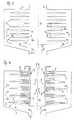
- zeigt schematisch in einer Längsschnittdarstellung eine Ausführungsform einer erfindungsgemäßen Filteranordnung mit austrittsseitig angeordneten, katalytisch aktiven Folien,
- Fig. 2
- eine zu Fig. 1 ähnliche Ausführungsform mit eintrittsseitig angeordneten, katalytisch aktiven Folien,
- Fig. 3
- eine weitere Ausführungsform gemäß der Erfindung, bei der sowohl ein- als auch austrittsseitig katalytisch aktive Folien vorgesehen sind,
- Fig. 4
- eine weitere Ausführungsfom einer erfindungsgemäßen Filteranordnung, bei der austrittsseitig angeordneten, katalytisch aktiven Folien Dosiermittel für die Zufuhr eines Reduktionsmittels zugeordnet sind,
- Fig. 5
- eine Ausführungsform einer erfindungsgemäßen Filteranordnung ähnlich Fig. 4, wobei zusätzlich noch eintrittsseitig katalytische aktive Folien vorgesehen sind, und
- Fig. 6
- in einer stirnseitigen Ansicht die sternförmige Anordnung der Dosiermittel im Bereich eines Filterplattenringes der Filteranordnung nach Fig. 4 oder Fig. 5.
- Fig. 1
- shows schematically in a longitudinal sectional view an embodiment of a filter arrangement according to the invention with catalytically active foils arranged on the outlet side,
- Fig. 2
- 1 shows an embodiment similar to FIG. 1 with catalytically active foils arranged on the inlet side,
- Fig. 3
- a further embodiment according to the invention, in which both catalytically active films are provided on the entry and exit sides,
- Fig. 4
- a further embodiment of a filter arrangement according to the invention, in which dosing means for the supply of a reducing agent are assigned on the outlet side, catalytically active foils,
- Fig. 5
- 4 shows an embodiment of a filter arrangement according to the invention similar to FIG. 4, catalytic active films being additionally provided on the inlet side, and
- Fig. 6
- in an end view the star-shaped arrangement of the dosing means in the area of a filter plate ring of the filter arrangement according to FIG. 4 or FIG. 5.
Die Filteranordnungen gemäß den Fig. 1 bis 6 sind für Abgasreinigungsanlagen
von Kraftfahrzeug-Verbrennungsmotoren, insbesondere von Dieselmotoren,
vorgesehen. Alle Filteranordnungen gemäß den Fig. 1 bis 6
weisen jeweils ein Filtergehäuse lauf, in dem ein Paket aus ringförmigen
Filterplatten 2 angeordnet ist. Sowohl das Filtergehäuse 1 als auch das
Paket aus Filterplattenringen 2 ist rotationssymmetrisch zu einer Mittellängsachse
M der Filteranordnung gestaltet. Das Filtergehäuse 1 weist
einen Eintritt E für die zu reinigende Abgasströmung und einen am gegenüberliegenden
Ende des Filtergehäuses 1 vorgesehenen Austritt A für
die gereinigte Abgasströmung auf. Die Abgasströmung ist bei allen Ausführungsbeispielen
gemäß den Fig. 1 bis 5 durch entsprechende Pfeile in
ihrem Verlauf optisch dargestellt, wobei die entsprechenden Pfeile lediglich
symbolisch bestimmte Teilströme darstellen. Dem Fachmann ist jedoch
klar, daß alle Filterplattenringe 2 innerhalb des Filtergehäuses 1 in
entsprechender Weise durchströmt werden.The filter arrangements according to FIGS. 1 to 6 are for exhaust gas cleaning systems
of motor vehicle internal combustion engines, in particular of diesel engines,
intended. All filter arrangements according to FIGS. 1 to 6
each have a filter housing in which a packet of
Die Filterplattenringe 2 sind porös gestaltet, um die Durchströmung des
Abgasstromes zu gewährleisten. Beim dargestellten Ausführungsbeispiel
sind die Filterplattenringe 2 als Sintermetallplatten gestaltet und tellerartig
ausgeführt. Dabei sind die Filterplattenringe 2 jeweils paarweise derart
zusammengefügt, daß sich zwischen jeweils zwei benachbarten Filterplattenringen
jeweils außen- und innenliegende Filtertaschen ergeben.
Die Filterplattenringe 2 sind sowohl im Bereich der äußeren Scheitelpunkte
3 der Filtertaschen, d. h. ihrer äußeren Ränder, als auch im Bereich
ihrer inneren Scheitelpunkte 4, d. h. im Bereich ihrer inneren Ränder,
umlaufend fest miteinander verbunden, vorzugsweise miteinander verschweißt.
Die im Bereich des Austritts A positionierten, endseitig Filterplattenringe
2 sind mit ihren inneren Scheitelpunkten, d. h. ihren inneren
Rändern, fest mit der Innenseite des Filtergehäuses 1 verbunden, insbesondere
verschweißt. Die Durchlässigkeit der Filterplattenringe 2 aufgrund
ihrer porösen Gestaltung als Sintermetallplatten it durch die gestrichelte
Darstellung der Filterplattenringe 2 verdeutlicht. Der zum Eintritt E benachbarte
Filterplattenring 2 ist im Bereich seines inneren Durchtrittes
durch eine Prallplatte 5 verschlossen, so daß die Abgasströmung, die in
das Filtergehäuse 1 eintritt, gemäß der Pfeildarstellung radial zur Mittellängsachse
M nach allen Seiten hin umgelenkt wird. Die Abgasströmung
durchdringt dann von außen her alle Filterplattenringe 2 nach innen hin,
wie anhand der Pfeildarstellung verdeutlicht ist. Vom Inneren des Paketes
aus Filterplattenringen aus wird die Abgasströmung dann zum Austritt A
geleitet.The filter plate rings 2 are porous to the flow of the
To ensure exhaust gas flow. In the illustrated embodiment
are the filter plate rings 2 designed as sintered metal plates and plate-like
executed. The filter plate rings 2 are each in pairs
put together that between two adjacent filter plate rings
result in external and internal filter bags.
The filter plate rings 2 are both in the area of the
Durch die poröse Gestaltung der Filterplattenringe 2 wird auf die radial von außen nach innen die Filterplattenringe 2 durchströmende Abgasströmung eine Filterwirkung ausgeübt, durch die sich entsprechende Feststoffpartikel innerhalb der Abgasströmung, wie insbesondere Ruß, an den Außenwandungen der Filterplattenringe 2 und damit im Bereich der außenliegenden Filtertaschen ablagern. The porous design of the filter plate rings 2 is radial Exhaust gas flow flowing through the filter plate rings 2 from outside to inside exerted a filtering effect through the corresponding Solid particles within the exhaust gas flow, such as soot in particular the outer walls of the filter plate rings 2 and thus in the area of Store external filter bags.
Die grundsätzliche Filterfunktion der Filteranordnungen gemäß den Fig. 1 bis 6, soweit sie bislang beschrieben worden sind, entspricht weitgehend der DE 198 10 738 C1, so daß bezüglich der Filterfunktion wie auch der paarweisen Zuordnung der Filterplatten ergänzend auf diese Druckschrift verwiesen wird.The basic filter function of the filter arrangements according to FIG. 1 to 6, as far as they have been described so far, largely corresponds DE 198 10 738 C1, so that with regard to the filter function as well Assignment of the filter plates in pairs in addition to this publication is referred.
Um für die Filteranordnungen 1 gemäß den Fig. 1 bis 6 zusätzlich noch
Katalysatorfunktionen erfüllen zu können, sind den durch die Filterplattenringe
2 geschaffenen Filtertaschen katalytisch aktive Folien, 6, 6a, 6b zugeordnet,
die anhand der einzelnen Ausführungsbeispiele in Aufbau und
Funktion nachfolgend näher beschrieben werden. Alle Folien 6, 6a, 6b
sind scheibenringförmig gestaltet und im Bereich der inneren oder der äußeren
Scheitelpunkte 3, 4 des Paketes der Filterplattenringe 2 zwischen
jeweils zwei benachbarte Filterplattenringe 2 eingebunden. Die Folien 6
bestehen vorzugsweise aus Metallfolien, die entsprechend katalytisch aktiv
beschichtet sind. Die Folien 6 können zwischen die Filterplattenringe 6
eingeschweißt sein. Die Folien 6 sind radial zur Mittellängsachse M ausgerichtet
und ragen in die Mitte der im Querschnitt dreieckigen, außen-
oder innenliegenden Filtertaschen hinein. Die Folien 6, 6a, 6b sind somit
lediglich im Bereich des jeweiligen Scheitelpunktes 3, 4 fest mit den Filterplattenringen
2 verbunden und ragen im übrigen frei in die jeweilige
Filtertasche hinein ab. Die Folien 6, 6a, 6b können in nicht näher dargestellter
Weise mit einer Versteifungsstruktur in Form von Verrippungen,
Stegen oder Prägungen versehen sein, wodurch die Steifigkeit der jeweiligen
Folien 6, 6a, 6b erhöht wird. Ergänzend oder alternativ können die
Filterplattenringe 2 in ebenfalls nicht näher dargestellter Weise mit in die
jeweiligen Filtertaschen hineinragenden Noppenstrukturen versehen sein,
die die Folien 6, 6a, 6b zumindest teilweise von beiden Seiten her punktartig
stützen. Die Noppen sind rechtwinklig zu den Folien 6 ausgerichtet
und greifen von beiden Seiten an jeder Folie 6, 6a, 6b an.To additionally for the
Die Filteranordnungen 1 nach den Fig. 1 und 2 weisen oxidationskatalytisch
aktiv beschichtete Folien 6a, 6b, auf, die beim Ausführungsbeispiel
nach Fig. 1 innenseitig und damit austrittsseitig der Filterplattenringe 2
und beim Ausführungsbeispiel nach Fig. 2 außenseitig und damit eintrittsseitig
der Filterplattenringe 2 angeordnet sind. Bei der austrittsseitigen
Anordnung gemäß Fig. 1 wird insbesondere eine Oxidation von HC und
CO im Abgasstrom erzielt, wobei die Oberfläche der Folien 6a in ihrer
Aktivität durch Ablagerungen nicht beeinträchtigt ist. Denn diese Ablagerungen
werden außenseitig, d. h. abgaseintrittsseitig, an den Filterplattenringen
2 abgefangen.The
Bei der außenseitigen, d. h. abgaseintrittsseitigen Anordnung der Folien 6b dienen diese insbesondere zur Oxidation von Rußpartikeln innerhalb der Abgasströmung, so daß die Ablagerungen derartiger Partikel auf den Folien 6b stattfinden, wodurch die Filterplattenringe 2 durch Rußablagerungen nicht oder weniger belastet werden.With the outside, d. H. arrangement of the foils on the exhaust gas inlet side 6b, these serve in particular for the oxidation of soot particles within the exhaust gas flow, so that the deposits of such particles on the Foils 6b take place, causing the filter plate rings 2 due to soot deposits not be burdened or less.
Beim Ausführungsbeispiel nach Fig. 3. wird die Katalysatoroberfläche verdoppelt,
indem im Bereich aller Filtertaschen, d. h. sowohl ein- als auch
austrittsseitig der Filterplattenringe 2 entsprechende oxidationskatalytisch
aktive Folien 6a, 6b angeordnet sind. Dabei werden mit den außenliegende
Folien 6b Funktionen und Vorteile des Ausführungsbeispiels nach Fig.
2 und den innenliegenden Folien 6a Vorteile und Funktionen des Ausführungsbeispiels
nach Fig. 1 erreicht.3, the catalyst surface is doubled,
by in the area of all filter bags, d. H. both one and one
corresponding catalytic oxidation on the outlet side of the filter plate rings 2
active foils 6a, 6b are arranged. Doing so with the outside
Foils 6b functions and advantages of the embodiment according to FIG.
2 and the inner foils 6a advantages and functions of the
Beim Ausführungsbeispiel nach Fig. 4 weist die Filteranordnung in dem
Filtergehäuse 1 katalytisch aktiv beschichtete Folien 6c auf, die zur Reduktion
von Stickoxiden dienen. Die bezüglich der Stickoxidreduktion katalytisch
aktiven Folien gemäß den Fig. 4 und 5 sind mit dem Bezugszeichen
6c versehen, um den Unterschied zu den oxidationskatalytisch aktiven
Folien 6, 6a, 6b darzulegen. Diese Folien 6c ragen in die innenliegenden
Filtertaschen hinein und sind somit austrittsseitig angeordnet. Um den
Folien 6c für die katalytische Reduktion das entsprechende Reduktionsmittel
zuzuführen, vorliegend Ammoniak, sind den Folien 6c Dosiermittel
7, 8 zugeordnet, die eine Eindüsung des Ammoniaks ermöglichen. Hierzu
sind drei gleichmäßig über den Umfang verteilte, parallel zur Mittellängsachse
M verlaufende Kanalabschnitte 7 vorgesehen (Fig. 6), die beidseitig
jeder Folie 6c mit radial nach außen abragenden Abzweigungen in Form
von Düsenkanälen 8 versehen sind. Die entsprechend katalytisch aktiven
Folien können auch eintrittsseitig der Filterplattenringe 2 angeordnet sein.
Selbstverständlich kann gemäß Fig. 5 auch die doppelte Anzahl von Folien
vorgesehen sein, um die katalytisch wirksame Fläche zu verdoppeln. 4, the filter arrangement in the
Gemäß einen nicht dargestellten Ausführungsbeispiel ist es auch möglich, die bezüglich der Stickoxidreduktion katalytisch wirksamen Folien mit oxidationskatalytisch aktiven Folien zu kombinieren und außen- und/oder innenseitige Anordnungen dieser Folien im Bereich der Filtertaschen vorzusehen.According to an embodiment not shown, it is also possible the films which are catalytically active with respect to nitrogen oxide reduction with oxidation catalytic to combine active foils and exterior and / or to provide internal arrangements of these foils in the area of the filter bags.
Claims (10)
Applications Claiming Priority (2)
| Application Number | Priority Date | Filing Date | Title |
|---|---|---|---|
| DE10035544A DE10035544B4 (en) | 2000-07-21 | 2000-07-21 | Filter arrangement for an emission control system |
| DE10035544 | 2000-07-21 |
Publications (2)
| Publication Number | Publication Date |
|---|---|
| EP1174599A1 true EP1174599A1 (en) | 2002-01-23 |
| EP1174599B1 EP1174599B1 (en) | 2005-04-06 |
Family
ID=7649739
Family Applications (1)
| Application Number | Title | Priority Date | Filing Date |
|---|---|---|---|
| EP01117067A Expired - Lifetime EP1174599B1 (en) | 2000-07-21 | 2001-07-13 | Filter system for an exhaust gas cleaning device |
Country Status (3)
| Country | Link |
|---|---|
| US (1) | US6923941B2 (en) |
| EP (1) | EP1174599B1 (en) |
| DE (2) | DE10035544B4 (en) |
Cited By (2)
| Publication number | Priority date | Publication date | Assignee | Title |
|---|---|---|---|---|
| WO2003054364A2 (en) * | 2001-12-20 | 2003-07-03 | Johnson Matthey Public Limited Company | Method and apparatus for filtering partriculate matter and selective catalytic reduction of nox |
| US7200989B2 (en) | 2002-10-15 | 2007-04-10 | Robert Bosch Gmbh | Apparatus and method for cleaning exhaust gas from an internal combustion engine |
Families Citing this family (11)
| Publication number | Priority date | Publication date | Assignee | Title |
|---|---|---|---|---|
| EP1348838A1 (en) * | 2002-03-26 | 2003-10-01 | Siemens Aktiengesellschaft | Exhaust gas purification apparatus and method for regeneration of a particulate filter |
| DE10250050A1 (en) * | 2002-10-25 | 2004-05-06 | Purem Abgassysteme Gmbh & Co. Kg | Exhaust aftertreatment system, especially for a diesel engine |
| DE102004026798A1 (en) * | 2004-06-02 | 2005-12-22 | Daimlerchrysler Ag | exhaust particulate filter |
| US7611561B2 (en) * | 2006-07-20 | 2009-11-03 | Benteler Automotive Corporation | Diesel exhaust filter construction |
| WO2009020835A2 (en) | 2007-08-03 | 2009-02-12 | Errcive, Inc. | Porous bodies and methods |
| US8277743B1 (en) | 2009-04-08 | 2012-10-02 | Errcive, Inc. | Substrate fabrication |
| US8359829B1 (en) | 2009-06-25 | 2013-01-29 | Ramberg Charles E | Powertrain controls |
| US8302389B2 (en) * | 2009-11-23 | 2012-11-06 | International Engine Intellectual Property Company, Llc | Urea SCR diesel aftertreatment system |
| US9833932B1 (en) | 2010-06-30 | 2017-12-05 | Charles E. Ramberg | Layered structures |
| CN105927319B (en) * | 2016-06-28 | 2018-08-24 | 广州市新力金属有限公司 | A kind of washing regeneration tail gas filtration system for internal combustion engine |
| CN114377491B (en) * | 2021-12-04 | 2023-06-06 | 徐州市万达石英有限公司 | Quartz polishing dust adsorption device |
Citations (9)
| Publication number | Priority date | Publication date | Assignee | Title |
|---|---|---|---|---|
| DE3322439A1 (en) * | 1983-06-22 | 1985-01-03 | Bedia Maschinenfabrik Verwaltungs GmbH, 5300 Bonn | Device for reducing the pollutant contents in the exhaust gases from an internal combustion engine |
| EP0325111A2 (en) * | 1988-01-21 | 1989-07-26 | Leistritz Aktiengesellschaft | Filter and afterburning device for exhaust gases, especially for internal combustion engines |
| EP0470365A1 (en) * | 1990-07-13 | 1992-02-12 | Schwäbische Hüttenwerke GmbH | Filter |
| DE4203128A1 (en) * | 1991-02-06 | 1992-08-13 | Nissan Motor | IC engine exhaust soot filter partic. for diesel engines - has filter element composed of porous foamed ceramic plates stacked in gas flow direction and having channels |
| US5193340A (en) * | 1990-05-10 | 1993-03-16 | Nissan Motor Co., Ltd. | Exhaust gas purifying system for internal combustion engine |
| US5213781A (en) * | 1990-10-08 | 1993-05-25 | Kabushiki Kaisha Riken | Method of cleaning nitrogen oxide containing exhaust gas |
| EP0779096A1 (en) * | 1995-12-13 | 1997-06-18 | Daimler-Benz Aktiengesellschaft | Process and device for catalytic gas purification |
| US5758496A (en) * | 1992-09-28 | 1998-06-02 | Ford Global Technologies, Inc. | Particulate and exhaust gas emission control system |
| DE19810738C1 (en) * | 1998-03-12 | 1999-04-22 | Hjs Fahrzeugtechnik Gmbh & Co | Cleaning of filter elements in the exhaust of diesel engines |
Family Cites Families (6)
| Publication number | Priority date | Publication date | Assignee | Title |
|---|---|---|---|---|
| DE3923985C1 (en) * | 1989-07-20 | 1990-06-28 | Daimler-Benz Aktiengesellschaft, 7000 Stuttgart, De | |
| US6284201B1 (en) * | 1993-02-10 | 2001-09-04 | Alfred Buck | Apparatus for the catalytic purification of flowing gases, in particular exhaust gases of internal combustion engines |
| US5682740A (en) * | 1995-05-12 | 1997-11-04 | Isuzu Ceramics Research Institute Co., Ltd. | Diesel particulate filter apparatus |
| JP3378432B2 (en) * | 1995-05-30 | 2003-02-17 | 住友電気工業株式会社 | Particulate trap for diesel engine |
| US5766455A (en) * | 1996-04-30 | 1998-06-16 | Zentox Corporation | Fibrous matte support for the photopromoted catalyzed degradation of compounds in a fluid stream |
| DE19901760A1 (en) * | 1999-01-18 | 2000-07-27 | Emitec Emissionstechnologie | Method and arrangement for cleaning an exhaust gas stream of a gasoline engine flowing in an exhaust line |
-
2000
- 2000-07-21 DE DE10035544A patent/DE10035544B4/en not_active Expired - Fee Related
-
2001
- 2001-07-13 DE DE50105809T patent/DE50105809D1/en not_active Expired - Lifetime
- 2001-07-13 EP EP01117067A patent/EP1174599B1/en not_active Expired - Lifetime
- 2001-07-19 US US09/909,281 patent/US6923941B2/en not_active Expired - Fee Related
Patent Citations (9)
| Publication number | Priority date | Publication date | Assignee | Title |
|---|---|---|---|---|
| DE3322439A1 (en) * | 1983-06-22 | 1985-01-03 | Bedia Maschinenfabrik Verwaltungs GmbH, 5300 Bonn | Device for reducing the pollutant contents in the exhaust gases from an internal combustion engine |
| EP0325111A2 (en) * | 1988-01-21 | 1989-07-26 | Leistritz Aktiengesellschaft | Filter and afterburning device for exhaust gases, especially for internal combustion engines |
| US5193340A (en) * | 1990-05-10 | 1993-03-16 | Nissan Motor Co., Ltd. | Exhaust gas purifying system for internal combustion engine |
| EP0470365A1 (en) * | 1990-07-13 | 1992-02-12 | Schwäbische Hüttenwerke GmbH | Filter |
| US5213781A (en) * | 1990-10-08 | 1993-05-25 | Kabushiki Kaisha Riken | Method of cleaning nitrogen oxide containing exhaust gas |
| DE4203128A1 (en) * | 1991-02-06 | 1992-08-13 | Nissan Motor | IC engine exhaust soot filter partic. for diesel engines - has filter element composed of porous foamed ceramic plates stacked in gas flow direction and having channels |
| US5758496A (en) * | 1992-09-28 | 1998-06-02 | Ford Global Technologies, Inc. | Particulate and exhaust gas emission control system |
| EP0779096A1 (en) * | 1995-12-13 | 1997-06-18 | Daimler-Benz Aktiengesellschaft | Process and device for catalytic gas purification |
| DE19810738C1 (en) * | 1998-03-12 | 1999-04-22 | Hjs Fahrzeugtechnik Gmbh & Co | Cleaning of filter elements in the exhaust of diesel engines |
Cited By (4)
| Publication number | Priority date | Publication date | Assignee | Title |
|---|---|---|---|---|
| WO2003054364A2 (en) * | 2001-12-20 | 2003-07-03 | Johnson Matthey Public Limited Company | Method and apparatus for filtering partriculate matter and selective catalytic reduction of nox |
| WO2003054364A3 (en) * | 2001-12-20 | 2003-08-28 | Johnson Matthey Plc | Method and apparatus for filtering partriculate matter and selective catalytic reduction of nox |
| US7264785B2 (en) | 2001-12-20 | 2007-09-04 | Johnson Matthey Public Limited Company | Selective catalytic reduction |
| US7200989B2 (en) | 2002-10-15 | 2007-04-10 | Robert Bosch Gmbh | Apparatus and method for cleaning exhaust gas from an internal combustion engine |
Also Published As
| Publication number | Publication date |
|---|---|
| DE50105809D1 (en) | 2005-05-12 |
| US6923941B2 (en) | 2005-08-02 |
| DE10035544A1 (en) | 2002-01-31 |
| DE10035544B4 (en) | 2012-01-05 |
| EP1174599B1 (en) | 2005-04-06 |
| US20020021988A1 (en) | 2002-02-21 |
Similar Documents
| Publication | Publication Date | Title |
|---|---|---|
| DE112005002903B4 (en) | Exhaust gas purification device for internal combustion engine | |
| EP1728984B2 (en) | Exhaust system | |
| EP1556587B1 (en) | Exhaust gas aftertreatment system, especially for a diesel engine | |
| EP1399241B1 (en) | Particle filter for the exhaust gas of internal combustion engines | |
| EP1830042B1 (en) | Static mixer and exhaust after treatment system | |
| EP1174599A1 (en) | Filter system for an exhaust gas cleaning device | |
| EP2129638B1 (en) | Diesel particle filter with a ceramic filter body | |
| WO2013135442A1 (en) | Exhaust gas cleaning device | |
| EP1917423B1 (en) | Process and device for treating exhaust fumes from an internal combustion engine | |
| EP0638711B1 (en) | Exhaust gas catalyst, in particular for cars | |
| DE102015004641A1 (en) | Filter element, in particular for gas filtration | |
| EP1304152B1 (en) | Exhaust system with particle filter for an internal combustion engine | |
| EP0470365B1 (en) | Filter | |
| EP2461887B1 (en) | Filter device and use of a wound filter element | |
| EP1688597A2 (en) | Exhaust gas cleaning device | |
| DE19932778A1 (en) | Apparatus for catalytic purification of exhaust gases from internal combustion engines has housing with exhaust gas inlet and outlet pipes, within which catalyst is arranged in opposing direction to the exhaust gas and the middle sections | |
| DE102004000044B4 (en) | Air filtration system | |
| DE4303586A1 (en) | Exhaust emission controller for IC engine - has tubular filter elements with regenerative heaters embedded in thickened walls and mounted in tubular housing | |
| EP1431528B1 (en) | Exhaust purification device | |
| WO2005068050A1 (en) | Filtering device, particularly for the exhaust system of an internal combustion engine | |
| DE102008031874B4 (en) | Exhaust gas purification device for an internal combustion engine of a vehicle, in particular a utility vehicle and arrangement of an exhaust gas purification device | |
| DE102010005890A1 (en) | Exhaust-gas treatment device for use as e.g. nitrogen oxide filter in exhaust line of waste gas system to clean nitrogen oxide from internal combustion engine, has filter bodies extending between housing sections over width of cabinet | |
| DE10357950A1 (en) | Combustion engine exhaust gas system, e.g. for a turbo diesel motor vehicle, has pulsation damping element in the exhaust gas line and or the exhaust gas recirculation line | |
| DE202007002430U1 (en) | Diesel particulate filter with a ceramic filter body | |
| WO2017140667A1 (en) | Filter system for the filtration of a hot unfiltered gas, and filter element for such a filter system |
Legal Events
| Date | Code | Title | Description |
|---|---|---|---|
| PUAI | Public reference made under article 153(3) epc to a published international application that has entered the european phase |
Free format text: ORIGINAL CODE: 0009012 |
|
| AK | Designated contracting states |
Kind code of ref document: A1 Designated state(s): AT BE CH CY DE DK ES FI FR GB GR IE IT LI LU MC NL PT SE TR Kind code of ref document: A1 Designated state(s): DE FR GB |
|
| AX | Request for extension of the european patent |
Free format text: AL;LT;LV;MK;RO;SI |
|
| 17P | Request for examination filed |
Effective date: 20020708 |
|
| AKX | Designation fees paid |
Free format text: DE FR GB |
|
| 17Q | First examination report despatched |
Effective date: 20030109 |
|
| GRAP | Despatch of communication of intention to grant a patent |
Free format text: ORIGINAL CODE: EPIDOSNIGR1 |
|
| GRAS | Grant fee paid |
Free format text: ORIGINAL CODE: EPIDOSNIGR3 |
|
| GRAA | (expected) grant |
Free format text: ORIGINAL CODE: 0009210 |
|
| AK | Designated contracting states |
Kind code of ref document: B1 Designated state(s): DE FR GB |
|
| REG | Reference to a national code |
Ref country code: GB Ref legal event code: FG4D Free format text: NOT ENGLISH |
|
| REG | Reference to a national code |
Ref country code: IE Ref legal event code: FG4D Free format text: LANGUAGE OF EP DOCUMENT: GERMAN |
|
| REF | Corresponds to: |
Ref document number: 50105809 Country of ref document: DE Date of ref document: 20050512 Kind code of ref document: P |
|
| GBT | Gb: translation of ep patent filed (gb section 77(6)(a)/1977) |
Effective date: 20050525 |
|
| PLBE | No opposition filed within time limit |
Free format text: ORIGINAL CODE: 0009261 |
|
| STAA | Information on the status of an ep patent application or granted ep patent |
Free format text: STATUS: NO OPPOSITION FILED WITHIN TIME LIMIT |
|
| ET | Fr: translation filed | ||
| 26N | No opposition filed |
Effective date: 20060110 |
|
| REG | Reference to a national code |
Ref country code: GB Ref legal event code: 732E |
|
| REG | Reference to a national code |
Ref country code: FR Ref legal event code: TP |
|
| PGFP | Annual fee paid to national office [announced via postgrant information from national office to epo] |
Ref country code: GB Payment date: 20130731 Year of fee payment: 13 Ref country code: FR Payment date: 20130730 Year of fee payment: 13 |
|
| PGFP | Annual fee paid to national office [announced via postgrant information from national office to epo] |
Ref country code: DE Payment date: 20130930 Year of fee payment: 13 |
|
| REG | Reference to a national code |
Ref country code: DE Ref legal event code: R119 Ref document number: 50105809 Country of ref document: DE |
|
| GBPC | Gb: european patent ceased through non-payment of renewal fee |
Effective date: 20140713 |
|
| REG | Reference to a national code |
Ref country code: FR Ref legal event code: ST Effective date: 20150331 |
|
| PG25 | Lapsed in a contracting state [announced via postgrant information from national office to epo] |
Ref country code: DE Free format text: LAPSE BECAUSE OF NON-PAYMENT OF DUE FEES Effective date: 20150203 |
|
| REG | Reference to a national code |
Ref country code: DE Ref legal event code: R119 Ref document number: 50105809 Country of ref document: DE Effective date: 20150203 |
|
| PG25 | Lapsed in a contracting state [announced via postgrant information from national office to epo] |
Ref country code: FR Free format text: LAPSE BECAUSE OF NON-PAYMENT OF DUE FEES Effective date: 20140731 Ref country code: GB Free format text: LAPSE BECAUSE OF NON-PAYMENT OF DUE FEES Effective date: 20140713 |