EP1174343B1 - Device for banding a packed good unity - Google Patents
Device for banding a packed good unity Download PDFInfo
- Publication number
- EP1174343B1 EP1174343B1 EP01116301A EP01116301A EP1174343B1 EP 1174343 B1 EP1174343 B1 EP 1174343B1 EP 01116301 A EP01116301 A EP 01116301A EP 01116301 A EP01116301 A EP 01116301A EP 1174343 B1 EP1174343 B1 EP 1174343B1
- Authority
- EP
- European Patent Office
- Prior art keywords
- film
- opening
- package unit
- curtain
- double
- Prior art date
- Legal status (The legal status is an assumption and is not a legal conclusion. Google has not performed a legal analysis and makes no representation as to the accuracy of the status listed.)
- Expired - Lifetime
Links
Images


Classifications
-
- B—PERFORMING OPERATIONS; TRANSPORTING
- B65—CONVEYING; PACKING; STORING; HANDLING THIN OR FILAMENTARY MATERIAL
- B65B—MACHINES, APPARATUS OR DEVICES FOR, OR METHODS OF, PACKAGING ARTICLES OR MATERIALS; UNPACKING
- B65B9/00—Enclosing successive articles, or quantities of material, e.g. liquids or semiliquids, in flat, folded, or tubular webs of flexible sheet material; Subdividing filled flexible tubes to form packages
- B65B9/02—Enclosing successive articles, or quantities of material between opposed webs
- B65B9/026—Enclosing successive articles, or quantities of material between opposed webs the webs forming a curtain
-
- B—PERFORMING OPERATIONS; TRANSPORTING
- B65—CONVEYING; PACKING; STORING; HANDLING THIN OR FILAMENTARY MATERIAL
- B65B—MACHINES, APPARATUS OR DEVICES FOR, OR METHODS OF, PACKAGING ARTICLES OR MATERIALS; UNPACKING
- B65B11/00—Wrapping, e.g. partially or wholly enclosing, articles or quantities of material, in strips, sheets or blanks, of flexible material
Definitions
- the invention relates to a device for banding a Packgutech with a foil band, with a a gate forming frame, with one through the gate extending, consisting of at least one conveyor Conveying line for the packaged goods unit, with drivable film rolls, their film webs at their ends with each other are connected and form a foil curtain in the gate as well arranged on both sides of the gate, against each other movable Double welding beam, whereby the packaged goods unit by the door conveyed through in a first conveying direction and takes the foil curtain with it, so that this seen in the first conveying direction frontally and laterally around the Packgutaji around, and then move the double welding beams together and the film curtain behind the Packgutü through Seal the film webs together.
- the disadvantage here is that when moving the Welding the film curtain is contracted and thus an additional tension on the film banding is applied. This can lead to relocation the goods come Packgutä and / or overstretching the film done.
- the object of the invention is to avoid these disadvantages and to provide a device of the aforementioned type, with the tension of the film when closing and welding the film banding reduced and / or targeted can be.
- a device for banding a packaged goods unit with a foil band with a gate forming a frame, with a through extending the gate, from at least one conveyor existing conveyor line for the packaged unit, with drivable Film rolls whose film webs at their ends are interconnected and in the gate a foil curtain form and arranged with both sides of the gate, against each other movable double welding beam, the Packaged goods through the gate in a first conveying direction is conveyed through and the film curtain here entrains, so that seen in the first conveying direction frontally and laterally around the Packgutaji around, and then the double welding bars move together and the film curtain behind the Packgutü by welding the film webs together close, at least temporarily targeted attitude of the Film tension during the collapse of the double welding bars a facility for relocating the beyond the door located Packgutaji against the first, normal conveying direction provided back to the gate is.
- the Foil in one half of the packaged unit width approximately corresponding distance from the end of Packguttician of the Double welding beams are captured and the Packguttician at least temporarily when moving together the double welding bars are moved closer to them, so that the tension of the foil is about constant remains and a shift of the goods of the packaged unit is avoided.
- the tension of banding will be affected, z. B. only during the second half of the movement of Double welding bars.
- the means for relocating the Packgutgut at least partially beyond the gate located also contrary to the normal conveying direction be operable conveyor of the conveyor line, so without additional technical equipment an opposite Movement of Packgutü can be done.
- the conveyor line can be horizontal and the door with the film curtain be arranged vertically, so with a simple technical structure a corresponding packaging the packaged goods unit is possible.
- the conveyor (s) can (for example).
- the conveyor line can be vertical and the gate with the Foil curtain can be arranged horizontally, so too a vertical stress generating packaging, e.g. B. by means Vertical stretch, can be done.
- the conveyor (s) can (as) with support arms or the like engaging in free spaces of the packaged goods unit (r)
- Carrying conveyor be formed so that the Packgutüau topic for packing the packaged goods unit are freely accessible.
- the invention also relates a device for banding a packaged goods unit with a foil band, with a packaged goods unit and a gate forming one Frame, with drivable film rolls whose film webs are connected at their ends and in the gate one Foil curtain form as well as with both sides of the gate arranged, mutually movable double welding bars, the gate with the foil curtain by means of a Traversing device in a first traversing direction via the packaged goods unit is moved over and the film curtain it gets stuck on the packaged unit and itself Seen in the first conveying direction frontally and laterally around this sets, and then the double welding bars move together and behind the foil curtain the Packgutaji by welding the film webs close together and at least temporarily targeted adjustment of the film tension during the collision the double welding beam means for relocation the gate located beyond the packaged goods unit with the double welding beam against the first, normal Travel direction back to the packaged goods unit is provided.
- the film in one half of the packaged unit width in about the appropriate distance from the end of Packgutaji are captured by the double welding beams and the double welding beams at least temporarily closer together be approached to the packaged unit so that the tension of the film is approximately constant remains and a shift of the goods of the packaged unit is avoided.
- the shuttle can be horizontal and the gate be arranged vertically with the film curtain, or it the moving device can be vertical and the gate with the Foil curtain be arranged horizontally.
- a stopper as limit stop of Be provided Bristolverfahrweges, so that an accurate Positioning can be done.
- a control device and at least one sensor for detection the Zu Wegverfahrweges be provided, wherein at least a sensor is designed as a light barrier and / or at least a sensor may be designed as a contact switch can.
- the sensors can either be near the Double welding bar be arranged and thus the double welding bar detect the facing end of the packaged goods unit or at a distance from the double welding bars be provided and thus facing away from the double welding beam Detect the end of the packaged goods unit.
- a control device for controlling the travel paths the conveyor and / or the traversing provided so that a positioning of the packaged goods unit or the door with the double welding beam for the appropriate packing stages easily and accurately can.
- a Device for detecting the movement of double welding bars in particular a rotary encoder, an angle encoder or the like may be provided so that depending the movement of the foil attached to pendulum arms and pulleys the drive speed of the Film rolls can be controlled.
- the axes of the film rolls can be horizontal extend and diverters for those of the Foil rolls provided for curtain running film webs be so that when changing the film rolls then a Film roll using a forklift or hand pallet truck as delivered on a pallet, can be inserted into the device, causing the Handling effort and the risk of accident when changing rolls of film is reduced.
- a Film roll using a forklift or hand pallet truck as delivered on a pallet can be inserted into the device, causing the Handling effort and the risk of accident when changing rolls of film is reduced.
- At least one page of the frame there is also the possibility of at least one page of the frame to arrange several rolls of film one above the other. Then one of the film rolls can serve as a supply roll, which is put into operation when the other roll of film is consumed. Then dead times are reduced when Film change. But you can also use film rolls use different film formats, each be used if necessary. In smaller spaces The film rolls can be arranged on one side. Here, the film web for one side of the film curtain passed over the device.
- each one is Film roll a Reibradantrieb attacking on its circumference assigned, and there are film storage for the film webs envisaged on their way to the film curtain.
- the Speed of the drives is no longer on the number of cycles the device or the transport speed of Packaged goods dependent, because the film storage can constantly filled and emptied when needed. That's enough Foil storage with at least one dancer roller.
- the conveyor 1 extends through a device 4 for Banderolieren the Packgutaji 3 with a foil band and further by a shrinking machine 5 more common Construction up to a discharge end 6.
- a cabinet 7th In the area of the task end 2 is a cabinet 7th
- a plurality of conveyors 1, 1a, 1b, on both sides of the (closed) double welding bar 16 are arranged, be provided so that the weld take place at a greater height of the film webs 12, 12a can.
- a frame 9, which is a gate. 8 forms, through which the partially not shown Conveyor 1 extends.
- Both sides of the gate 8 are on the outside of the frame 9 bearings 10, 10a for horizontally therein to be stored, in FIG. 4 for the sake of clarity not shown film rolls 11, 11 a arranged.
- the designs shown in the figures are on each Side of the frame 9 in each case two film rolls 11, 11 a arranged with horizontally extending axes. It but can also only one film roll 11, 11 a per Be arranged side.
- Control device integrated, which controls the Zuschverfahrweges, in particular depending from a sensor for detecting the position of the packaged goods unit performs.
- sensors may preferably contact switch and / or Photoelectric sensors 18 are used.
- the illustrated device operates as follows:
- film webs 12, 12a each have a foil curtain.
- this foil curtain drives a transported on the conveyor 1 Packguttician 3 and takes the film curtain with, so that the Packguttician 3 turn over on three sides with foil becomes.
- the two drive on both sides the conveyor 1 arranged double welding bar 16, 16 a together and lead the film webs 12, 12 a to the rear fourth side of Packguttician 3 around until they are about in the middle or outside the middle.
- the two film webs 12, 12 a with a Double weld provided and by a not shown Heating wire in the middle between the double weld separated, so that for the following Packgutguttician 3 another film curtain is created.
- the friction wheel drives 17, 17a of the film rolls 11, 11a can regardless of the transport speed of the conveyor 1 and the clock speed of the device practically without Interruption work, so that constantly foil webs 12, 12a introduced into the associated film storage 13, 13a become.
- the film webs located in the film store 13, 13a are subtracted therefrom if necessary, i. when a new Packguttician 3 enters the gate 8 and while the there located foil curtain entrains.
- the by the upward movement resulting path change between film curtain and film rolls 11, 11a are passed over the dancer roller 14, 14 a in the film storage 13, 13 a balanced.
- the second film curtain can also be overlapping to the first foil curtain are arranged when Packgutechen 3 to be banded, whose height is greater as the height of a foil curtain.
- the deflection device 15, 15a in its height position method, wherein the film memory 13, 13 a the Path change compensates. It can both only one Pair of film rolls 11a be movable, but it can also several pairs of film rolls 11, 11a changeable in their position be.
- the conveyor 1 is at least temporarily during the collision the double welding bar 16 against the normal Moving direction to the door 8 out, so that the Packgutü 3 closer to the double welding bar 16 zoom is moved.
- the position the packaged goods unit 3 is detected by a light barrier 18, and the control device in the control cabinet 7 stops the backward movement of the conveyor.
- a device for detecting the movement of the double welding bars 16 in particular a rotary encoder, a Angular encoder or the like for controlling the film roll drives can depend on the movement of the Pendulum mounted film and pulleys the drive speed the film rolls 11, 11 a controlled become.
Landscapes
- Engineering & Computer Science (AREA)
- Mechanical Engineering (AREA)
- Basic Packing Technique (AREA)
- Packaging Of Special Articles (AREA)
- Auxiliary Devices For And Details Of Packaging Control (AREA)
- Containers And Plastic Fillers For Packaging (AREA)
- Control And Other Processes For Unpacking Of Materials (AREA)
- Vending Machines For Individual Products (AREA)
- Labeling Devices (AREA)
Abstract
Description
Die Erfindung betrifft eine Vorrichtung zum Banderolieren einer Packguteinheit mit einer Folienbanderole, mit einem ein Tor bildenden Gestell, mit einer sich durch das Tor erstreckenden, aus zumindest einem Förderer bestehenden Förderstrecke für die Packguteinheit, mit antreibbaren Folienrollen, deren Folienbahnen an ihren Enden miteinander verbunden sind und im Tor einen Folienvorhang bilden sowie mit beidseits des Tors angeordneten, gegeneinander beweglichen Doppelschweißbalken, wobei die Packguteinheit durch das Tor in einer ersten Förderrichtung hindurchgefördert wird und den Folienvorhang dabei mitnimmt, so dass sich dieser in der ersten Förderrichtung gesehen frontal und seitlich um die Packguteinheit herum legt, und anschließend die Doppelschweißbalken zusammenfahren und den Folienvorhang hinter der Packguteinheit durch Verschweißen der Folienbahnen miteinander verschließen.The invention relates to a device for banding a Packguteinheit with a foil band, with a a gate forming frame, with one through the gate extending, consisting of at least one conveyor Conveying line for the packaged goods unit, with drivable film rolls, their film webs at their ends with each other are connected and form a foil curtain in the gate as well arranged on both sides of the gate, against each other movable Double welding beam, whereby the packaged goods unit by the door conveyed through in a first conveying direction and takes the foil curtain with it, so that this seen in the first conveying direction frontally and laterally around the Packguteinheit around, and then move the double welding beams together and the film curtain behind the Packguteinheit through Seal the film webs together.
Aus der Praxis sind derartige Vorrichtungen aus der DE 299 02 910 Ul bekannt, die zur Banderolierung von Packguteinheiten verwendet werden, die mit Stretch- oder Schrumpffolien verpackt werden. From practice, such devices from DE 299 02 910 Ul known for the banding of Packguteinheiten can be used with stretch or Shrink films are packed.
Nachteilig hierbei ist, dass beim Zusammenfahren der Schweißbalken der Folienvorhang zusammengezogen wird und somit eine zusätzliche Spannung auf die Folienbanderolierung aufgebracht wird. Hierdurch kann es zur Verlagerung der Ware der Packguteinheit kommen und/oder eine Überdehnung der Folie erfolgen.The disadvantage here is that when moving the Welding the film curtain is contracted and thus an additional tension on the film banding is applied. This can lead to relocation the goods come Packguteinheit and / or overstretching the film done.
Aufgabe der Erfindung ist es, diese Nachteile zu vermeiden und eine Vorrichtung der vorgenannten Art anzugeben, mit der die Spannung der Folie beim Schließen und Schweißen der Folienbanderolierung reduziert und/oder gezielt eingestellt werden kann.The object of the invention is to avoid these disadvantages and to provide a device of the aforementioned type, with the tension of the film when closing and welding the film banding reduced and / or targeted can be.
Diese Aufgabe wird gelöst durch eine Vorrichtung zum Banderolieren einer Packguteinheit mit einer Folienbanderole, mit einem ein Tor bildenden Gestell, mit einer sich durch das Tor erstreckenden, aus zumindest einem Förderer bestehenden Förderstrecke für die Packguteinheit, mit antreibbaren Folienrollen, deren Folienbahnen an ihren Enden miteinander verbunden sind und im Tor einen Folienvorhang bilden sowie mit beidseits des Tors angeordneten, gegeneinander beweglichen Doppelschweißbalken, wobei die Packguteinheit durch das Tor in einer ersten Förderrichtung hindurchgefördert wird und den Folienvorhang dabei mitnimmt, so dass sich dieser in der ersten Förderrichtung gesehen frontal und seitlich um die Packguteinheit herum legt, und anschließend die Doppelschweißbalken zusammenfahren und den Folienvorhang hinter der Packguteinheit durch Verschweißen der Folienbahnen miteinander verschließen, wobei zur zumindest zeitweisen gezielten Einstellung der Folienspannung während des Zusammenfahrens der Doppelschweißbalken eine Einrichtung zur Verlagerung der jenseits des Tors befindlichen Packguteinheit entgegen der ersten, normalen Förderrichtung zurück zum Tor hin vorgesehen ist. Hierdurch kann von den Doppelschweißbalken die Folie in einem der Hälfte der Packguteinheitbreite in etwa entsprechenden Abstand vom Ende der Packguteinheit von den Doppelschweißbalken erfasst werden und die Packguteinheit zumindest zeitweise beim Zusammenfahren der Doppelschweißbalken näher an diese herangefahren werden, so dass die Spannung der Folie in etwa konstant bleibt und eine Verlagerung der Ware der Packguteinheit vermieden wird. Durch entsprechendes Verfahren der Packguteinheit mittels Steuerung des Förderers kann auch gezielt die Spannung der Banderolierung beeinflusst werden, z. B. erst während der zweiten Hälfte der Bewegung der Doppelschweißbalken.This object is achieved by a device for banding a packaged goods unit with a foil band, with a gate forming a frame, with a through extending the gate, from at least one conveyor existing conveyor line for the packaged unit, with drivable Film rolls whose film webs at their ends are interconnected and in the gate a foil curtain form and arranged with both sides of the gate, against each other movable double welding beam, the Packaged goods through the gate in a first conveying direction is conveyed through and the film curtain here entrains, so that seen in the first conveying direction frontally and laterally around the Packguteinheit around, and then the double welding bars move together and the film curtain behind the Packguteinheit by welding the film webs together close, at least temporarily targeted attitude of the Film tension during the collapse of the double welding bars a facility for relocating the beyond the door located Packguteinheit against the first, normal conveying direction provided back to the gate is. As a result of the double welding bar the Foil in one half of the packaged unit width approximately corresponding distance from the end of Packguteinheit of the Double welding beams are captured and the Packguteinheit at least temporarily when moving together the double welding bars are moved closer to them, so that the tension of the foil is about constant remains and a shift of the goods of the packaged unit is avoided. By appropriate method of Packguteinheit by controlling the conveyor can also be targeted the tension of banding will be affected, z. B. only during the second half of the movement of Double welding bars.
Hierbei kann z. B. die Packguteinheit erst in der zweiten Hälfte der Bewegung der Doppelschweißbalken zum Verschweißen der Folienbahnen näher an die Doppelschweißbalken herangefahren werden.This z. B. the Packguteinheit only in the second Half of the movement of the double welding beam for welding the film webs moved closer to the double welding beam become.
Je nach Erfordernis können auch mehrere Förderer, die beidseits der (geschlossenen) Doppelschweißbalken angeordnet sind, vorgesehen sein, so dass die Schweißung auf einer größeren Höhe der Folienbahnen erfolgen kann.Depending on the requirement, several sponsors may also be involved arranged on both sides of the (closed) double welding beam are, be provided so that the weld on a greater height of the film webs can be done.
Vorzugsweise kann die Einrichtung zur Verlagerung der Packguteinheit ein zumindest teilweise jenseits des Tors befindlicher, auch entgegen der normalen Förderrichtung betreibbarer Förderer der Förderstrecke sein, so dass ohne zusätzliche technische Einrichtungen eine entgegengesetzte Bewegung der Packguteinheit erfolgen kann.Preferably, the means for relocating the Packgutgut at least partially beyond the gate located, also contrary to the normal conveying direction be operable conveyor of the conveyor line, so without additional technical equipment an opposite Movement of Packguteinheit can be done.
Dabei kann die Förderstrecke horizontal und das Tor mit dem Folienvorhang vertikal angeordnet sein, so dass mit einem einfachen technischen Aufbau ein entsprechendes Verpacken der Packguteinheit möglich ist.The conveyor line can be horizontal and the door with the film curtain be arranged vertically, so with a simple technical structure a corresponding packaging the packaged goods unit is possible.
In diesem Fall kann(können) die(der) Förderer z. B. als Band- oder Kettenförderer ausgebildet sein. In this case, the conveyor (s) can (for example). B. as Belt or chain conveyor be formed.
Auch kann die Förderstrecke vertikal und das Tor mit dem Folienvorhang horizontal angeordnet sein, so dass auch eine Vertikalspannung erzeugende Verpackung, z. B. mittels Vertikalstretch, erfolgen kann.Also, the conveyor line can be vertical and the gate with the Foil curtain can be arranged horizontally, so too a vertical stress generating packaging, e.g. B. by means Vertical stretch, can be done.
Dabei kann(können) die(der) Förderer als mit Tragarmen oder dergleichen in Freiräume der Packguteinheit eingreifende(r) Tragförderer ausgebildet sein, so dass die Packguteinheitaußenflächen zum Verpacken der Packguteinheit frei zugänglich sind.In this case, the conveyor (s) can (as) with support arms or the like engaging in free spaces of the packaged goods unit (r) Carrying conveyor be formed so that the Packguteinheitaußenflächen for packing the packaged goods unit are freely accessible.
Die Erfindung betrifft auch eine Vorrichtung zum Banderolieren einer Packguteinheit mit einer Folienbanderole, mit einer Packguteinheit und einem ein Tor bildenden Gestell, mit antreibbaren Folienrollen, deren Folienbahnen an ihren Enden miteinander verbunden sind und im Tor einen Folienvorhang bilden sowie mit beidseits des Tors angeordneten, gegeneinander beweglichen Doppelschweißbalken, wobei das Tor mit dem Folienvorhang mittels einer Verfahreinrichtung in einer ersten Verfahrrichtung über die Packguteinheit hinüber gefahren wird und der Folienvorhang dabei an der Packguteinheit hängenbleibt und sich in der ersten Förderrichtung gesehen frontal und seitlich um diese herum legt, und anschließend die Doppelschweißbalken zusammenfahren und den Folienvorhang hinter der Packguteinheit durch Verschweißen der Folienbahnen miteinander verschließen und bei der zur zumindest zeitweisen gezielten Einstellung der Folienspannung während des Zusammenfahrens der Doppelschweißbalken eine Einrichtung zur Verlagerung des jenseits der Packguteinheit befindlichen Tors mit den Doppelschweißbalken entgegen der ersten, normalen Verfahrrichtung zurück zu der Packguteinheit hin vorgesehen ist. Hierdurch kann von den Doppelschweißbalken die Folie in einem der Hälfte der Packguteinheitbreite in etwa entsprechenden Abstand vom Ende der Packguteinheit von den Doppelschweißbalken erfasst werden und die Doppelschweißbalken zumindest zeitweise beim Zusammenfahren näher an die Packguteinheit herangefahren werden, sodass die Spannung der Folie in etwa konstant bleibt und eine Verlagerung der Ware der Packguteinheit vermieden wird.The invention also relates a device for banding a packaged goods unit with a foil band, with a packaged goods unit and a gate forming one Frame, with drivable film rolls whose film webs are connected at their ends and in the gate one Foil curtain form as well as with both sides of the gate arranged, mutually movable double welding bars, the gate with the foil curtain by means of a Traversing device in a first traversing direction via the packaged goods unit is moved over and the film curtain it gets stuck on the packaged unit and itself Seen in the first conveying direction frontally and laterally around this sets, and then the double welding bars move together and behind the foil curtain the Packguteinheit by welding the film webs close together and at least temporarily targeted adjustment of the film tension during the collision the double welding beam means for relocation the gate located beyond the packaged goods unit with the double welding beam against the first, normal Travel direction back to the packaged goods unit is provided. As a result of the double welding beam the film in one half of the packaged unit width in about the appropriate distance from the end of Packguteinheit are captured by the double welding beams and the double welding beams at least temporarily closer together be approached to the packaged unit so that the tension of the film is approximately constant remains and a shift of the goods of the packaged unit is avoided.
Hierbei können z. B. die Doppelschweißbalken erst in der zweiten Hälfte ihrer Bewegung zum Verschweißen der Folienbahnen näher an die Packguteinheit herangeführt werden.This z. B. the double welding bar only in the second half of their movement to weld the film webs be brought closer to the Packguteinheit.
Dabei kann die Verfahreinrichtung horizontal und das Tor mit dem Folienvorhang vertikal angeordnet sein, oder es kann die Verfahreinrichtung vertikal und das Tor mit dem Folienvorhang horizontal angeordnet sein.The shuttle can be horizontal and the gate be arranged vertically with the film curtain, or it the moving device can be vertical and the gate with the Foil curtain be arranged horizontally.
Vorzugsweise kann ein Stopper als Begrenzungsanschlag des Zurückverfahrweges vorgesehen sein, so dass eine genaue Positionierung erfolgen kann.Preferably, a stopper as limit stop of Be provided zurückverfahrweges, so that an accurate Positioning can be done.
Auch kann zur Steuerung des Zurückverfahrweges eine Steuereinrichtung sowie wenigstens ein Sensor zur Erfassung des Zurückverfahrweges vorgesehen sein, wobei zumindest ein Sensor als Lichtschranke ausgebildet und/oder wenigstens ein Sensor als Kontaktschalter ausgebildet sein kann. Hierbei können die Sensoren entweder in der Nähe der Doppelschweißbalken angeordnet sein und somit das den Doppelschweißbalken zugewandte Ende der Packguteinheit erfassen oder aber in einem Abstand von den Doppelschweißbalken vorgesehen sein und somit das den Doppelschweißbalken abgewandte Ende der Packguteinheit detektieren.Also, to control the Rückverfahrweges a control device and at least one sensor for detection the Zurückverfahrweges be provided, wherein at least a sensor is designed as a light barrier and / or at least a sensor may be designed as a contact switch can. Here, the sensors can either be near the Double welding bar be arranged and thus the double welding bar detect the facing end of the packaged goods unit or at a distance from the double welding bars be provided and thus facing away from the double welding beam Detect the end of the packaged goods unit.
Auch kann eine Steuervorrichtung zur Steuerung der Verfahrwege der Förderer und/oder der Verfahreinrichtung vorgesehen sein, so dass eine Positionierung der Packguteinheit bzw. des Tors mit den Doppelschweißbalken für die entsprechenden Verpackungsstadien leicht und genau erfolgen kann. Also, a control device for controlling the travel paths the conveyor and / or the traversing provided so that a positioning of the packaged goods unit or the door with the double welding beam for the appropriate packing stages easily and accurately can.
Ferner kann zur Steuerung der Folienrollenantriebe eine Einrichtung zur Erfassung der Bewegung der Doppelschweißbalken, insbesondere ein Drehimpulsgeber, ein Winkelcodierer oder dergleichen vorgesehen sein, so dass in Abhängigkeit der Bewegung der an Pendelarmen angebrachten Folien- und Umlenkrollen die Antriebsgeschwindigkeit der Folienrollen gesteuert werden kann.Furthermore, to control the film roll drives a Device for detecting the movement of double welding bars, in particular a rotary encoder, an angle encoder or the like may be provided so that depending the movement of the foil attached to pendulum arms and pulleys the drive speed of the Film rolls can be controlled.
Vorzugsweise können die Achsen der Folienrollen sich horizontal erstrecken und Umlenkeinrichtungen für die von den Folienrollen zum Vorhang laufenden Folienbahnen vorgesehen sein, so dass bei einem Wechsel der Folienrollen dann eine Folienrolle mit Hilfe eines Staplers oder eines Handhubwagens so, wie sie auf einer Palette angeliefert wird, in die Vorrichtung eingelegt werden kann, wodurch der Handlingsaufwand und die Unfallgefahr beim Wechsel von Folienrollen reduziert wird. Dazu ist es vorteilhaft, wenn außenseitig am Gestell Lager für die Achsen der Folienrollen angeordnet sind.Preferably, the axes of the film rolls can be horizontal extend and diverters for those of the Foil rolls provided for curtain running film webs be so that when changing the film rolls then a Film roll using a forklift or hand pallet truck as delivered on a pallet, can be inserted into the device, causing the Handling effort and the risk of accident when changing rolls of film is reduced. For this it is advantageous if on the outside of the frame bearings for the axes of the film rolls are arranged.
Es besteht auch die Möglichkeit, auf zumindest einer Seite des Gestells mehrere Folienrollen übereinander anzuordnen. Dann kann eine der Folienrollen als Vorratsrolle dienen, die in Betrieb genommen wird, wenn die andere Folienrolle verbraucht ist. Dann reduzieren sich Totzeiten beim Folienwechsel. Man kann aber auch Folienrollen mit unterschiedlichen Folienformaten einsetzen, die jeweils bei Bedarf benutzt werden. Bei geringeren Platzverhältnissen können die Folienrollen einseitig angeordnet werden. Hierbei wird die Folienbahn für die eine Seite des Folienvorhangs über die Vorrichtung geführt.There is also the possibility of at least one page of the frame to arrange several rolls of film one above the other. Then one of the film rolls can serve as a supply roll, which is put into operation when the other roll of film is consumed. Then dead times are reduced when Film change. But you can also use film rolls use different film formats, each be used if necessary. In smaller spaces The film rolls can be arranged on one side. Here, the film web for one side of the film curtain passed over the device.
Bei einer bevorzugten Ausführung der Erfindung ist jeder Folienrolle ein an ihrem Umfang angreifender Reibradantrieb zugeordnet, und es sind Folienspeicher für die Folienbahnen auf ihrem Weg zum Folienvorhang vorgesehen. Damit können elektronische Regelungen für die Drehzahl der Antriebe zur Anpassung an den durch den Folienverbrauch kleiner werdenden Umfang der Folienrollen entfallen. Die Drehzahl der Antriebe ist auch nicht mehr von der Taktzahl der Vorrichtung oder von der Transportgeschwindigkeit der Packguteinheiten abhängig, denn die Folienspeicher können laufend gefüllt und bei Bedarf geleert werden. Dazu genügen Folienspeicher mit wenigstens einer Tänzerwalze.In a preferred embodiment of the invention, each one is Film roll a Reibradantrieb attacking on its circumference assigned, and there are film storage for the film webs envisaged on their way to the film curtain. In order to can electronic regulations for the speed of the Drives to adapt to the through the film consumption Smaller scope of the film rolls omitted. The Speed of the drives is no longer on the number of cycles the device or the transport speed of Packaged goods dependent, because the film storage can constantly filled and emptied when needed. That's enough Foil storage with at least one dancer roller.
Im Folgenden wird ein in der Zeichnung dargestelltes Ausführungsbeispiel der Erfindung erläutert. Es zeigen:
- Fig. 1
- schematisch eine Seitenansicht einer Anlage zum Banderolieren einer Packguteinheit mit einer Folienbanderole, die anschließend geschrumpft wird,
- Fig. 2
- eine Draufsicht auf den Gegenstand nach Fig. 1,
- Fig. 3
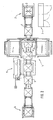
- eine Ansicht der Vorrichtung zum Banderolieren einer Packguteinheit mit einer Folienbanderole,
- Fig. 4
- eine Seitenansicht des Gegenstandes nach Fig. 3 und
- Fig. 5
- eine Draufsicht auf den Gegenstand nach Fig. 3.
- Fig. 1
- 1 is a schematic side view of a system for banding a packaged goods unit with a film band, which is then shrunk,
- Fig. 2
- a top view of the article of FIG. 1,
- Fig. 3
- a view of the device for banding a Packguteinheit with a foil band,
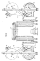
- Fig. 4
- a side view of the article of FIG. 3 and
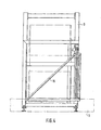
- Fig. 5
- a plan view of the article of FIG. 3rd
In den Fig. 1 und 2 erkennt man einen Förderer 1 mit einem
Aufgabeende 2 zur Aufnahme von Packguteinheiten 3, die
insbesondere aus palettierten Gutstapeln bestehen können.
Der Förderer 1 erstreckt sich durch eine Vorrichtung 4 zum
Banderolieren der Packguteinheit 3 mit einer Folienbanderole
und weiter durch eine Schrumpfmaschine 5 üblicher
Bauart bis zu einem Abgabeende 6. In dem Bereich des Aufgabeendes
2 befindet sich ein Schaltschrank 7.In Figs. 1 and 2 can be seen a conveyor 1 with a
Je nach Erfordernis können auch mehrere Förderer 1, 1a,
1b, die beidseits der (geschlossenen) Doppelschweißbalken
16 angeordnet sind, vorgesehen sein, so dass die Schweißung
auf einer größeren Höhe der Folienbahnen 12, 12a erfolgen
kann.Depending on the requirement, a plurality of conveyors 1, 1a,
1b, on both sides of the (closed) double welding bar
16 are arranged, be provided so that the weld
take place at a greater height of the
Zur Vorrichtung 4 zum Banderolieren gehört, wie aus den
Fig. 3 bis 5 ersichtlich, ein Gestell 9, welches ein Tor 8
bildet, durch welches sich der teilweise nicht dargestellte
Förderer 1 erstreckt. Beidseits des Tors 8 sind
außenseitig am Gestell 9 Lager 10, 10a für darin horizontal
zu lagernde, in der Fig. 4 der Übersichtlichkeit halber
nicht dargestellte Folienrollen 11, 11a angeordnet.
Bei den in den Figuren gezeigten Ausführungen sind auf jeder
Seite des Gestells 9 jeweils zwei Folienrollen 11, 11a
mit sich horizontal erstreckenden Achsen angeordnet. Es
kann aber auch jeweils nur eine Folienrolle 11, 11a pro
Seite angeordnet sein.Belongs to the device 4 for banding, as from the
3 to 5, a
Die von den Folienrollen 11, 11a abgezogenen Folienbahnen
12, 12a durchlaufen entsprechend Fig. 3 zunächst Folienspeicher
13, 13a, die zumindest eine Tänzerwalze 14, 14a
aufweisen, und werden dann jeweils über eine Umlenkeinrichtung
15, 15a geführt, die bei der dargestellten
Ausführung aus einer schräg gestellten, insbesondere mit
Teflon beschichteten oder komplett aus Teflon bestehenden
Rolle oder Schiene besteht, die die Folienbahnen 12, 12a
aus horizontaler Lage in eine vertikale Lage überführt. In
dieser vertikalen Lage werden die von beiden Seiten kommenden
Folienbahnen 12, 12a im Bereich des Tors 8 an ihren
jeweiligen Enden miteinander verbunden.The withdrawn from the film rolls 11, 11 a
Hierzu sind beidseits des Tors 8 Doppelschweißbalken 16,
16a angeordnet, die mit zugeordneten Antrieben gegeneinander
beweglich sind. Jeder Folienrolle 11, 11a ist ein an
ihrem Umfang angreifender Reibradantrieb 17, 17a zugeordnet.For this purpose, on both sides of the
Weiterhin ist in dem Schaltschrank 7 eine nicht näher dargestellte Steuereinrichtung integriert, welche die Steuerung des Zurückverfahrweges, insbesondere in Abhängigkeit von einem Sensor zur Erfassung der Position der Packguteinheit ausführt.Furthermore, in the cabinet 7 is not shown Control device integrated, which controls the Zurückverfahrweges, in particular depending from a sensor for detecting the position of the packaged goods unit performs.
Als Sensoren können vorzugsweise Kontaktschalter und/oder
Lichtschranken 18 verwendet werden.As sensors may preferably contact switch and / or
Die dargestellte Vorrichtung arbeitet wie folgt:The illustrated device operates as follows:
Im Tor 8 bilden die mit ihren Enden verbundenen Folienbahnen
12, 12a jeweils einen Folienvorhang. In diesen Folienvorhang
fährt eine auf dem Förderer 1 transportierte
Packguteinheit 3 ein und nimmt den Folienvorhang mit, so
dass die Packguteinheit 3 dreiseitig mit Folie umschlagen
wird. Nachdem die Packguteinheit 3 durch Vor- oder Zurückfahren
positioniert wurde, fahren die beiden beidseits
des Förderers 1 angeordneten Doppelschweißbalken 16, 16a
zusammen und führen die Folienbahnen 12, 12a um die hintere
vierte Seite der Packguteinheit 3 herum, bis sie etwa
in der Mitte oder auch außerhalb der Mitte zusammentreffen.
Dort werden die beiden Folienbahnen 12, 12a mit einer
Doppelschweißnaht versehen und durch einen nicht dargestellten
Heizdraht in der Mitte zwischen der Doppelschweißnaht
getrennt, so dass für die folgende Packguteinheit
3 ein weiterer Folienvorhang entsteht.In the
Die Reibradantriebe 17, 17a der Folienrollen 11, 11a können
unabhängig von der Transportgeschwindigkeit des Förderers
1 und von der Taktzahl der Vorrichtung praktisch ohne
Unterbrechung arbeiten, so dass ständig Folienbahnen 12,
12a in die zugeordneten Folienspeicher 13, 13a eingeführt
werden. Die im Folienspeicher 13, 13a befindlichen Folienbahnen
werden daraus bei Bedarf abgezogen, d.h. wenn eine
neue Packguteinheit 3 in das Tor 8 einfährt und dabei den
dort befindlichen Folienvorhang mitnimmt.The friction wheel drives 17, 17a of the film rolls 11, 11a can
regardless of the transport speed of the conveyor
1 and the clock speed of the device practically without
Interruption work, so that constantly foil
Wenn eine Folienrolle 11, 11a verbraucht ist, kann zunächst
ohne Wechsel der Folienrolle 11, 11a die andere Folienrolle
11, 11a in Betrieb genommen werden. Man kann
aber auch auf jeder Seite des Gestells 9 Folienrollen 11,
11a mit unterschiedlichen Folienbreiten einsetzen und hat
dann die Möglichkeit für einen schnellen Wechsel des
Folienformates.When a
Auch kann, was in den Figuren nicht dargestellt ist, ein
zweiter Folienvorhang vorgesehen sein, wobei der inaktive
Folienvorhang nach oben gefahren ist. Die durch die Aufwärtsbewegung
entstehende Wegänderung zwischen Folienvorhang
und Folienrollen 11, 11a wird über die Tänzerwalze
14, 14a im Folienspeicher 13, 13a ausgeglichen.Also, what is not shown in the figures, a
be provided second curtain, wherein the inactive
Slide curtain is moved up. The by the upward movement
resulting path change between film curtain
and film rolls 11, 11a are passed over the dancer roller
14, 14 a in the
Der zweite Folienvorhang kann aber auch überlappend zum
ersten Folienvorhang angeordnet werden, wenn Packguteinheiten
3 banderoliert werden sollen, deren Höhe größer ist
als die Höhe eines Folienvorhangs. The second film curtain can also be overlapping to the
first foil curtain are arranged when
Hierbei wird die Umlenkeinrichtung 15, 15a in ihrer Höhenposition
verfahren, wobei der Folienspeicher 13, 13a die
Wegänderung ausgleicht. Dabei können sowohl lediglich ein
Paar Folienrollen 11a verfahrbar sein, es können aber auch
mehrere Paare Folienrollen 11, 11a in ihrer Position veränderlich
sein.Here, the
Um die Spannung des Folienvorhangs konstant zu halten,
wird der Förderer 1 zumindest zeitweise während des Zusammenfahrens
der Doppelschweißbalken 16 entgegen der normalen
Förderrichtung zum Tor 8 hin verfahren, so dass die
Packguteinheit 3 näher an die Doppelschweißbalken 16 heran
bewegt wird. Um eine Kollision der Packguteinheit 3 mit
den Doppelschweißbalken 16 zu vermeiden, wird die Position
der Packguteinheit 3 von einer Lichtschranke 18 erfasst,
und die Steuereinrichtung in dem Schaltschrank 7 stoppt
die Rückwärtsbewegung des Förderers 1.To keep the tension of the foil curtain constant,
the conveyor 1 is at least temporarily during the collision
the double welding bar 16 against the normal
Moving direction to the
Über eine Einrichtung zur Erfassung der Bewegung der Doppelschweißbalken 16, insbesondere ein Drehimpulsgeber, ein Winkelcodierer oder dergleichen zur Steuerung der Folienrollenantriebe kann in Abhängigkeit der Bewegung der an Pendelarmen angebrachten Folien- und Umlenkrollen die Antriebsgeschwindigkeit der Folienrollen 11, 11a gesteuert werden.About a device for detecting the movement of the double welding bars 16, in particular a rotary encoder, a Angular encoder or the like for controlling the film roll drives can depend on the movement of the Pendulum mounted film and pulleys the drive speed the film rolls 11, 11 a controlled become.
Claims (15)
- Apparatus for wrapping a package unit (3) with a film wrapper, said apparatus having a frame (9) which forms an opening (8), a conveying path for the package unit (3), which path extends through the opening (8) and comprises at least one conveyor (1, 1a, 1b), drivable film rollers (11), the film webs (12) of which rollers are interconnected at their ends and form a film curtain in the opening (8), as well as double-welding bars (16) which are disposed on each side of the opening (8) and are displaceable relative to each other, the package unit (3) being conveyed through the opening (8) in a first conveying direction and entraining the film curtain thereby so that said curtain is placed around the package unit (3) frontally and laterally when viewed with respect to the first conveying direction, and the double-welding bars (16) subsequently moving towards each other and closing the film curtain behind the package unit (3) by welding the film webs together, characterised in that a means for displacing the package unit (3), situated beyond the opening (8), in the opposite direction to the first conveying direction back towards the opening (8) is provided for the at least temporary, appropriate setting of the film tension as the double-welding bars (16) move towards each other.
- Apparatus according to claim 1, characterised in that the means for displacing the package unit (3) is a conveyor (1, 1a, 1b) of the conveying path, said conveyor being situated at least partially beyond the opening (8) and also being drivable in the opposite direction to the normal conveying direction.
- Apparatus according to claim 1 or 2, characterised in that the conveying path is disposed horizontally, and the opening (8), provided with the film curtain, is disposed vertically.
- Apparatus according to claim 3, characterised in that the conveyors or conveyor (1, 1a, 1b) are or is in the form of belt or chain conveyors.
- Apparatus according to claim 1, characterised in that the conveying path is disposed vertically, and the opening (8), provided with the film curtain, is disposed horizontally.
- Apparatus according to claim 4, characterised in that the conveyors or conveyor (1, 1a, 1b) are or is in the form of supporting conveyors which engage in spaces of the package unit (3) by means of supporting arms.
- Apparatus for wrapping a package unit (3) with a film wrapper, said apparatus having a package unit (3) and a frame (9) which forms an opening (8), drivable film rollers (11), the film webs (12) of which rollers are interconnected at their ends and form a film curtain in the opening (8), as well as double-welding bars (16) which are disposed on each side of the opening (8) and are displaceable relative to each other, the opening (8), provided with the film curtain, being moved over the package unit (3) into a first displacement direction by means of a displacement means, and the film curtain thereby remaining suspended from the package unit (3) and being placed around said package unit frontally and laterally when viewed with respect to the first conveying direction, and the double-welding bars (16) subsequently moving towards each other and closing the film curtain behind the package unit (3) by welding the film webs together, characterised in that a means for displacing the opening (8), situated beyond the package unit (3), with the double-welding bars (16) in the opposite direction to the first conveying direction back towards the package unit (3) is provided for the at least temporary, appropriate setting of the film tension as the double-welding bars (16) move towards each other.
- Apparatus according to claim 7, characterised in that the displacement means is disposed horizontally, and the opening (8), provided with the film curtain, is disposed vertically.
- Apparatus according to claim 7, characterised in that the displacement means is disposed vertically, and the opening (8), provided with the film curtain, is disposed horizontally.
- Apparatus according to one of claims 1 to 9, characterised in that a stopper is provided as the limiting stop member for the rearward displacement path.
- Apparatus according to one of claims 1 to 10, characterised in that a control means is provided for controlling the rearward displacement path, and at least one sensor is provided for detecting the rearward displacement path.
- Apparatus according to claim 11, characterised in that at least one sensor is in the form of a light barrier.
- Apparatus according to claim 11 or 12, characterised in that at least one sensor is in the form of a contact switch.
- Apparatus according to one of claims 1 to 13, characterised in that a control apparatus is provided for controlling the displacement paths of the conveyors (1, 1a, 1b) and/or the displacement means.
- Apparatus according to one of claims 1 to 14, characterised in that a means for detecting the movement of the double-welding bars (16), more especially a rotary pulse transmitter or an angle encoder, is provided for controlling the film roller drives.
Applications Claiming Priority (2)
| Application Number | Priority Date | Filing Date | Title |
|---|---|---|---|
| DE20011854U | 2000-07-10 | ||
| DE20011854U DE20011854U1 (en) | 2000-07-10 | 2000-07-10 | Banding device |
Publications (3)
| Publication Number | Publication Date |
|---|---|
| EP1174343A1 EP1174343A1 (en) | 2002-01-23 |
| EP1174343B1 true EP1174343B1 (en) | 2004-10-20 |
| EP1174343B9 EP1174343B9 (en) | 2005-03-09 |
Family
ID=7943692
Family Applications (1)
| Application Number | Title | Priority Date | Filing Date |
|---|---|---|---|
| EP01116301A Expired - Lifetime EP1174343B9 (en) | 2000-07-10 | 2001-07-05 | Device for banding a packed good unity |
Country Status (15)
| Country | Link |
|---|---|
| US (1) | US6532719B2 (en) |
| EP (1) | EP1174343B9 (en) |
| KR (1) | KR20020005509A (en) |
| CN (1) | CN1191180C (en) |
| AT (1) | ATE280081T1 (en) |
| BR (1) | BR0103005B1 (en) |
| CA (1) | CA2352721C (en) |
| CZ (1) | CZ299980B6 (en) |
| DE (2) | DE20011854U1 (en) |
| DK (1) | DK1174343T3 (en) |
| ES (1) | ES2231350T3 (en) |
| HU (1) | HUP0102848A3 (en) |
| MX (1) | MXPA01007007A (en) |
| PL (1) | PL199126B1 (en) |
| SK (1) | SK285509B6 (en) |
Cited By (1)
| Publication number | Priority date | Publication date | Assignee | Title |
|---|---|---|---|---|
| DE202009008596U1 (en) | 2009-05-12 | 2009-09-24 | Msk - Verpackungs-Systeme Gmbh | Device for packing a load unit with foil |
Families Citing this family (11)
| Publication number | Priority date | Publication date | Assignee | Title |
|---|---|---|---|---|
| DE20011854U1 (en) * | 2000-07-10 | 2001-11-22 | MSK-Verpackungs-Systeme Gesellschaft mit beschränkter Haftung, 47533 Kleve | Banding device |
| DE10217253A1 (en) * | 2002-04-15 | 2003-10-23 | Optima Filling & Packaging | Machine for wrapping palletized articles comprises conveyor for articles and splicer for edges of sheets fed from reels on either side via guide rollers to splicer |
| ITBO20020232A1 (en) * | 2002-04-24 | 2003-10-24 | Aetna Group Spa | EQUIPMENT FOR BANDING GROUPS OF PALLETIZED PRODUCTS |
| DE10258553B8 (en) * | 2002-12-14 | 2005-12-08 | Leica Mikrosysteme Gmbh | Method for automatically approaching a specimen to a knife of a microtome or ultramicrotome |
| ES2594417T5 (en) | 2008-06-07 | 2023-05-03 | Msk Emballage S A R L | Device and method for stretching a tubular film over a stack of products |
| IT1403246B1 (en) | 2010-11-10 | 2013-10-17 | Sestese Off Mec | PERFECT EQUIPMENT FOR PACKING BY LOADING LOADS ON PALLETS WITH FILMS OF PLASTIC MATERIAL OF DIFFERENT HEIGHTS. |
| WO2013120116A1 (en) * | 2012-02-12 | 2013-08-15 | Shane Gordon Sparg | Methods of treating plants |
| US9623989B2 (en) * | 2013-03-01 | 2017-04-18 | The Procter & Gamble Company | Method and apparatus for bundling packages of absorbent articles |
| IT201800008202A1 (en) * | 2018-08-28 | 2020-02-28 | Messersi' Packaging Srl | Station for wrapping products with inclined sides |
| CA3168234A1 (en) * | 2021-07-19 | 2023-01-19 | Belco Packaging Systems, Inc. | Vertical sealer apparatus and methods of vertically sealing |
| US20230278742A1 (en) * | 2022-03-03 | 2023-09-07 | 1Mrobotics Ltd. | Autonomous packing system and method for packing goods |
Family Cites Families (10)
| Publication number | Priority date | Publication date | Assignee | Title |
|---|---|---|---|---|
| GB1112293A (en) * | 1964-05-26 | 1968-05-01 | Taylor Ltd C F | Wrapping machine and method |
| SE311123B (en) * | 1968-02-15 | 1969-05-27 | Iwema Ab | |
| DE2022577C3 (en) * | 1970-05-08 | 1980-03-13 | Kooperativa Foerbundet (Kf) Ekonomisk Foerening, Stockholm | Method and device for producing a weld seam on a film envelope placed under tension around a stack of packs |
| US3672116A (en) * | 1970-05-11 | 1972-06-27 | Kooperativa Foerbundet | Method and machine for packaging goods |
| FR2212263B1 (en) * | 1972-12-28 | 1979-06-29 | Thimon Hubert | |
| DE2701506A1 (en) * | 1977-01-15 | 1978-07-20 | Bella Italo Della | Banding machine for packaging of textiles etc. - has conveyor track, storage magazines and devices to lay, tension and close band placed round package |
| IT1230913B (en) * | 1989-06-23 | 1991-11-08 | Adelchi Ciarrocca | PROCEDURE AND DEVICE FOR THE WELDING OF GROUPS OF ITEMS WITH COLD IRONABLE PLASTIC FILM |
| ES1022952Y (en) * | 1992-11-13 | 1994-01-01 | Construcciones Metalicas J Bar | PERFECTED RETRACTILITY PACKING MACHINE. |
| DE29902910U1 (en) * | 1999-02-19 | 2000-03-30 | MSK-Verpackungs-Systeme Gesellschaft mit beschränkter Haftung, 47533 Kleve | Device for banding a packaged goods unit with a shrink film band |
| DE20011854U1 (en) * | 2000-07-10 | 2001-11-22 | MSK-Verpackungs-Systeme Gesellschaft mit beschränkter Haftung, 47533 Kleve | Banding device |
-
2000
- 2000-07-10 DE DE20011854U patent/DE20011854U1/en not_active Expired - Lifetime
-
2001
- 2001-07-05 AT AT01116301T patent/ATE280081T1/en active
- 2001-07-05 EP EP01116301A patent/EP1174343B9/en not_active Expired - Lifetime
- 2001-07-05 DE DE50104181T patent/DE50104181D1/en not_active Expired - Lifetime
- 2001-07-05 DK DK01116301T patent/DK1174343T3/en active
- 2001-07-05 ES ES01116301T patent/ES2231350T3/en not_active Expired - Lifetime
- 2001-07-06 PL PL348489A patent/PL199126B1/en unknown
- 2001-07-06 SK SK962-2001A patent/SK285509B6/en not_active IP Right Cessation
- 2001-07-09 HU HU0102848A patent/HUP0102848A3/en unknown
- 2001-07-09 CA CA002352721A patent/CA2352721C/en not_active Expired - Fee Related
- 2001-07-09 US US09/901,464 patent/US6532719B2/en not_active Expired - Lifetime
- 2001-07-10 MX MXPA01007007A patent/MXPA01007007A/en active IP Right Grant
- 2001-07-10 CZ CZ20012500A patent/CZ299980B6/en not_active IP Right Cessation
- 2001-07-10 CN CNB011224789A patent/CN1191180C/en not_active Expired - Lifetime
- 2001-07-10 BR BRPI0103005-1A patent/BR0103005B1/en not_active IP Right Cessation
- 2001-07-10 KR KR1020010041077A patent/KR20020005509A/en not_active Application Discontinuation
Cited By (2)
| Publication number | Priority date | Publication date | Assignee | Title |
|---|---|---|---|---|
| DE202009008596U1 (en) | 2009-05-12 | 2009-09-24 | Msk - Verpackungs-Systeme Gmbh | Device for packing a load unit with foil |
| EP2251267A1 (en) | 2009-05-12 | 2010-11-17 | Msk-Verpackungs-Systeme Gesellschaft Mit Beschränkter Haftung | Device and method for packaging a charging unit with film |
Also Published As
| Publication number | Publication date |
|---|---|
| PL348489A1 (en) | 2002-01-14 |
| US6532719B2 (en) | 2003-03-18 |
| CN1333164A (en) | 2002-01-30 |
| SK9622001A3 (en) | 2002-02-05 |
| KR20020005509A (en) | 2002-01-17 |
| DE20011854U1 (en) | 2001-11-22 |
| DK1174343T3 (en) | 2004-12-27 |
| CN1191180C (en) | 2005-03-02 |
| MXPA01007007A (en) | 2004-11-10 |
| BR0103005A (en) | 2002-03-05 |
| CA2352721C (en) | 2009-04-07 |
| PL199126B1 (en) | 2008-08-29 |
| EP1174343B9 (en) | 2005-03-09 |
| DE50104181D1 (en) | 2004-11-25 |
| CZ20012500A3 (en) | 2002-02-13 |
| HU0102848D0 (en) | 2001-09-28 |
| EP1174343A1 (en) | 2002-01-23 |
| ATE280081T1 (en) | 2004-11-15 |
| BR0103005B1 (en) | 2009-05-05 |
| CA2352721A1 (en) | 2002-01-10 |
| HUP0102848A2 (en) | 2002-05-29 |
| CZ299980B6 (en) | 2009-01-14 |
| US20020007617A1 (en) | 2002-01-24 |
| ES2231350T3 (en) | 2005-05-16 |
| SK285509B6 (en) | 2007-03-01 |
| HUP0102848A3 (en) | 2003-05-28 |
Similar Documents
| Publication | Publication Date | Title |
|---|---|---|
| EP0187981B1 (en) | Method and apparatus for feeding packages to a collecting and packaging station | |
| EP1174343B9 (en) | Device for banding a packed good unity | |
| EP2826735B1 (en) | Adjustable storage section of a conveyor device and method for the intermediate storage of items | |
| DE1786486B2 (en) | DEVICE FOR COLLECTING AND CONVEYING A GROUP OF PACKAGING UNITS, FOR EXAMPLE BOTTLES, CANS ETC. IN A STATION FOR COVERING SUCH PACKAGING UNITS IN PACKAGING MATERIAL | |
| EP1029786B1 (en) | Device for banderoling a package goods unit with a shrinkable banderole | |
| EP0604808A1 (en) | Packing machine | |
| DE102007028680A1 (en) | Goods e.g. soft cheese, grouping station for packaging machine, has goods pick-up unit movable position-synchronously to conveyor belt, where unit is positioned on goods and brought at preselectable distance to previously moved goods | |
| EP2707287A1 (en) | Method and device for strapping packagings, products for packaging or grouped items | |
| DE4214321C2 (en) | Device for turning packages | |
| EP0833791B1 (en) | Feed device for a packaging machine | |
| DE4313325C2 (en) | Device for filling and closing packages | |
| DE102013106187A1 (en) | Device and method for conveying, handling, packaging and / or palletizing of piece goods, packaged goods and / or containers | |
| DE19654373A1 (en) | Device for sealing lids on packages | |
| DE2127310A1 (en) | Conveyor device for packs | |
| DE69735261T2 (en) | Separation device for a high-speed packaging machine | |
| DE3638370A1 (en) | DEVICE FOR PACKING CONTINUOUSLY MOVING ITEMS WITH A SHRINK PACKING TAPE | |
| EP1088761A1 (en) | Apparatus for automatically applying transport handles to goods | |
| EP1089926B1 (en) | Conveyor section arrangement for containers being filled with items or bulk material at a filling station | |
| EP1238910A1 (en) | Method and apparatus for packaging elongate objects | |
| DE2935028A1 (en) | RETURNING MACHINE | |
| EP1520789B1 (en) | Device for introducing packages into boxes | |
| DE2117719B2 (en) | Machine for loading or unloading bottle crates, cardboard boxes and the like | |
| DE10305095A1 (en) | Device and method for changing pallets in an automatic palletizer | |
| DE4000588C2 (en) | Device for interrupting the filling process on a packaging machine | |
| DE4325009A1 (en) | Process and apparatus for transporting packs or the like |
Legal Events
| Date | Code | Title | Description |
|---|---|---|---|
| PUAI | Public reference made under article 153(3) epc to a published international application that has entered the european phase |
Free format text: ORIGINAL CODE: 0009012 |
|
| AK | Designated contracting states |
Kind code of ref document: A1 Designated state(s): AT BE CH CY DE DK ES FI FR GB GR IE IT LI LU MC NL PT SE TR |
|
| AX | Request for extension of the european patent |
Free format text: AL;LT;LV;MK;RO;SI |
|
| 17P | Request for examination filed |
Effective date: 20020228 |
|
| AKX | Designation fees paid |
Free format text: AT BE CH CY DE DK ES FI FR GB GR IE IT LI LU MC NL PT SE TR |
|
| 17Q | First examination report despatched |
Effective date: 20021227 |
|
| GRAP | Despatch of communication of intention to grant a patent |
Free format text: ORIGINAL CODE: EPIDOSNIGR1 |
|
| GRAS | Grant fee paid |
Free format text: ORIGINAL CODE: EPIDOSNIGR3 |
|
| GRAA | (expected) grant |
Free format text: ORIGINAL CODE: 0009210 |
|
| AK | Designated contracting states |
Kind code of ref document: B1 Designated state(s): AT BE CH CY DE DK ES FI FR GB GR IE IT LI LU MC NL PT SE TR |
|
| PG25 | Lapsed in a contracting state [announced via postgrant information from national office to epo] |
Ref country code: TR Free format text: LAPSE BECAUSE OF FAILURE TO SUBMIT A TRANSLATION OF THE DESCRIPTION OR TO PAY THE FEE WITHIN THE PRESCRIBED TIME-LIMIT Effective date: 20041020 Ref country code: IE Free format text: LAPSE BECAUSE OF FAILURE TO SUBMIT A TRANSLATION OF THE DESCRIPTION OR TO PAY THE FEE WITHIN THE PRESCRIBED TIME-LIMIT Effective date: 20041020 |
|
| REG | Reference to a national code |
Ref country code: GB Ref legal event code: FG4D Free format text: NOT ENGLISH |
|
| REG | Reference to a national code |
Ref country code: CH Ref legal event code: EP |
|
| GBT | Gb: translation of ep patent filed (gb section 77(6)(a)/1977) |
Effective date: 20041020 |
|
| REG | Reference to a national code |
Ref country code: SE Ref legal event code: TRGR |
|
| REG | Reference to a national code |
Ref country code: IE Ref legal event code: FG4D Free format text: GERMAN |
|
| REF | Corresponds to: |
Ref document number: 50104181 Country of ref document: DE Date of ref document: 20041125 Kind code of ref document: P |
|
| PG25 | Lapsed in a contracting state [announced via postgrant information from national office to epo] |
Ref country code: GR Free format text: LAPSE BECAUSE OF FAILURE TO SUBMIT A TRANSLATION OF THE DESCRIPTION OR TO PAY THE FEE WITHIN THE PRESCRIBED TIME-LIMIT Effective date: 20050120 |
|
| REG | Reference to a national code |
Ref country code: ES Ref legal event code: FG2A Ref document number: 2231350 Country of ref document: ES Kind code of ref document: T3 |
|
| REG | Reference to a national code |
Ref country code: IE Ref legal event code: FD4D |
|
| PG25 | Lapsed in a contracting state [announced via postgrant information from national office to epo] |
Ref country code: LU Free format text: LAPSE BECAUSE OF NON-PAYMENT OF DUE FEES Effective date: 20050705 Ref country code: CY Free format text: LAPSE BECAUSE OF FAILURE TO SUBMIT A TRANSLATION OF THE DESCRIPTION OR TO PAY THE FEE WITHIN THE PRESCRIBED TIME-LIMIT Effective date: 20050705 |
|
| PG25 | Lapsed in a contracting state [announced via postgrant information from national office to epo] |
Ref country code: MC Free format text: LAPSE BECAUSE OF NON-PAYMENT OF DUE FEES Effective date: 20050731 Ref country code: CH Free format text: LAPSE BECAUSE OF NON-PAYMENT OF DUE FEES Effective date: 20050731 Ref country code: LI Free format text: LAPSE BECAUSE OF NON-PAYMENT OF DUE FEES Effective date: 20050731 Ref country code: BE Free format text: LAPSE BECAUSE OF NON-PAYMENT OF DUE FEES Effective date: 20050731 |
|
| PLBE | No opposition filed within time limit |
Free format text: ORIGINAL CODE: 0009261 |
|
| STAA | Information on the status of an ep patent application or granted ep patent |
Free format text: STATUS: NO OPPOSITION FILED WITHIN TIME LIMIT |
|
| 26N | No opposition filed |
Effective date: 20050721 |
|
| ET | Fr: translation filed | ||
| REG | Reference to a national code |
Ref country code: CH Ref legal event code: PL |
|
| BERE | Be: lapsed |
Owner name: *MSK-VERPACKUNGS-SYSTEME G.M.B.H. Effective date: 20050731 |
|
| PG25 | Lapsed in a contracting state [announced via postgrant information from national office to epo] |
Ref country code: PT Free format text: LAPSE BECAUSE OF NON-PAYMENT OF DUE FEES Effective date: 20050320 |
|
| PGFP | Annual fee paid to national office [announced via postgrant information from national office to epo] |
Ref country code: GB Payment date: 20150724 Year of fee payment: 15 |
|
| PGFP | Annual fee paid to national office [announced via postgrant information from national office to epo] |
Ref country code: AT Payment date: 20150722 Year of fee payment: 15 |
|
| REG | Reference to a national code |
Ref country code: FR Ref legal event code: PLFP Year of fee payment: 16 |
|
| REG | Reference to a national code |
Ref country code: AT Ref legal event code: MM01 Ref document number: 280081 Country of ref document: AT Kind code of ref document: T Effective date: 20160705 |
|
| GBPC | Gb: european patent ceased through non-payment of renewal fee |
Effective date: 20160705 |
|
| PG25 | Lapsed in a contracting state [announced via postgrant information from national office to epo] |
Ref country code: AT Free format text: LAPSE BECAUSE OF NON-PAYMENT OF DUE FEES Effective date: 20160705 Ref country code: GB Free format text: LAPSE BECAUSE OF NON-PAYMENT OF DUE FEES Effective date: 20160705 |
|
| REG | Reference to a national code |
Ref country code: FR Ref legal event code: PLFP Year of fee payment: 17 |
|
| PGFP | Annual fee paid to national office [announced via postgrant information from national office to epo] |
Ref country code: NL Payment date: 20170720 Year of fee payment: 17 |
|
| PGFP | Annual fee paid to national office [announced via postgrant information from national office to epo] |
Ref country code: FI Payment date: 20170719 Year of fee payment: 17 |
|
| PGFP | Annual fee paid to national office [announced via postgrant information from national office to epo] |
Ref country code: SE Payment date: 20170724 Year of fee payment: 17 |
|
| REG | Reference to a national code |
Ref country code: FR Ref legal event code: PLFP Year of fee payment: 18 |
|
| REG | Reference to a national code |
Ref country code: NL Ref legal event code: MM Effective date: 20180801 |
|
| PG25 | Lapsed in a contracting state [announced via postgrant information from national office to epo] |
Ref country code: FI Free format text: LAPSE BECAUSE OF NON-PAYMENT OF DUE FEES Effective date: 20180705 |
|
| PG25 | Lapsed in a contracting state [announced via postgrant information from national office to epo] |
Ref country code: NL Free format text: LAPSE BECAUSE OF NON-PAYMENT OF DUE FEES Effective date: 20180801 Ref country code: SE Free format text: LAPSE BECAUSE OF NON-PAYMENT OF DUE FEES Effective date: 20180706 |
|
| PGFP | Annual fee paid to national office [announced via postgrant information from national office to epo] |
Ref country code: ES Payment date: 20200818 Year of fee payment: 20 Ref country code: DK Payment date: 20200722 Year of fee payment: 20 Ref country code: FR Payment date: 20200727 Year of fee payment: 20 Ref country code: DE Payment date: 20200622 Year of fee payment: 20 |
|
| PGFP | Annual fee paid to national office [announced via postgrant information from national office to epo] |
Ref country code: IT Payment date: 20200731 Year of fee payment: 20 |
|
| REG | Reference to a national code |
Ref country code: DE Ref legal event code: R071 Ref document number: 50104181 Country of ref document: DE |
|
| REG | Reference to a national code |
Ref country code: DK Ref legal event code: EUP Expiry date: 20210705 |
|
| REG | Reference to a national code |
Ref country code: ES Ref legal event code: FD2A Effective date: 20211026 |
|
| PG25 | Lapsed in a contracting state [announced via postgrant information from national office to epo] |
Ref country code: ES Free format text: LAPSE BECAUSE OF EXPIRATION OF PROTECTION Effective date: 20210706 |