EP0833791B1 - Feed device for a packaging machine - Google Patents
Feed device for a packaging machine Download PDFInfo
- Publication number
- EP0833791B1 EP0833791B1 EP96919522A EP96919522A EP0833791B1 EP 0833791 B1 EP0833791 B1 EP 0833791B1 EP 96919522 A EP96919522 A EP 96919522A EP 96919522 A EP96919522 A EP 96919522A EP 0833791 B1 EP0833791 B1 EP 0833791B1
- Authority
- EP
- European Patent Office
- Prior art keywords
- pushers
- drives
- pusher
- conveying
- chain
- Prior art date
- Legal status (The legal status is an assumption and is not a legal conclusion. Google has not performed a legal analysis and makes no representation as to the accuracy of the status listed.)
- Expired - Lifetime
Links
Images

Classifications
-
- B—PERFORMING OPERATIONS; TRANSPORTING
- B65—CONVEYING; PACKING; STORING; HANDLING THIN OR FILAMENTARY MATERIAL
- B65G—TRANSPORT OR STORAGE DEVICES, e.g. CONVEYORS FOR LOADING OR TIPPING, SHOP CONVEYOR SYSTEMS OR PNEUMATIC TUBE CONVEYORS
- B65G43/00—Control devices, e.g. for safety, warning or fault-correcting
- B65G43/10—Sequence control of conveyors operating in combination
-
- B—PERFORMING OPERATIONS; TRANSPORTING
- B65—CONVEYING; PACKING; STORING; HANDLING THIN OR FILAMENTARY MATERIAL
- B65G—TRANSPORT OR STORAGE DEVICES, e.g. CONVEYORS FOR LOADING OR TIPPING, SHOP CONVEYOR SYSTEMS OR PNEUMATIC TUBE CONVEYORS
- B65G17/00—Conveyors having an endless traction element, e.g. a chain, transmitting movement to a continuous or substantially-continuous load-carrying surface or to a series of individual load-carriers; Endless-chain conveyors in which the chains form the load-carrying surface
- B65G17/26—Conveyors having an endless traction element, e.g. a chain, transmitting movement to a continuous or substantially-continuous load-carrying surface or to a series of individual load-carriers; Endless-chain conveyors in which the chains form the load-carrying surface comprising a series of co-operating units, e.g. interconnected by pivots
-
- B—PERFORMING OPERATIONS; TRANSPORTING
- B65—CONVEYING; PACKING; STORING; HANDLING THIN OR FILAMENTARY MATERIAL
- B65G—TRANSPORT OR STORAGE DEVICES, e.g. CONVEYORS FOR LOADING OR TIPPING, SHOP CONVEYOR SYSTEMS OR PNEUMATIC TUBE CONVEYORS
- B65G2201/00—Indexing codes relating to handling devices, e.g. conveyors, characterised by the type of product or load being conveyed or handled
- B65G2201/02—Articles
-
- B—PERFORMING OPERATIONS; TRANSPORTING
- B65—CONVEYING; PACKING; STORING; HANDLING THIN OR FILAMENTARY MATERIAL
- B65G—TRANSPORT OR STORAGE DEVICES, e.g. CONVEYORS FOR LOADING OR TIPPING, SHOP CONVEYOR SYSTEMS OR PNEUMATIC TUBE CONVEYORS
- B65G2203/00—Indexing code relating to control or detection of the articles or the load carriers during conveying
- B65G2203/04—Detection means
- B65G2203/042—Sensors
- B65G2203/044—Optical
Definitions
- From CH-A-412 708 (GB-PS-1.060.219) or US-PS-4,068,756 are feeding devices to one Packaging machine known. From an endless, revolving Chain are taken along, which in a regular Division are arranged. With the solution after U.S. Patent 4,068,756 stand off the chain at each joint laterally from which the drivers are attached are. The division can be changed by repositioning. The length of the carrier's orbit must be an integer multiple of the division. To achieve this, a loop is formed on the lower strand of the chain, over which the drivers are guided through a bypass. The upstream deflection wheel of the chain is in the conveying direction adjustable.
- the present invention has for its object a To design a conveyor of the type mentioned at the beginning, that they are compared to the solutions described above is easier. This task is accomplished through the combination of features of claims solved.
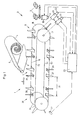
- the conveyor device 1 shown schematically in FIG. 1 serves to supply products 2 (Figure 2), e.g. of groups biscuits upright, to a mere hint Packaging machine 3.
- the packaging machine can Tubular bag packaging machine e.g. according to EP-B-399 Be 848.
- the packaging machine 3 has a supply roll 4 of wrapping material film 5.
- the exit station 6 of the working section 7 the device 1, the products 2 are enveloped by the film 5.
- the longitudinal edges 8 of the film 5 by sealing and Transport wheels 9 sealed together so that a Hose formed around the spaced products 2 becomes.
- the wheels 9 are driven by a motor 10.
- the motor 10 is connected to a rotary encoder 11. Downstream the wheels 9 are not shown Cross sealing jaws with separating knives the final sealing and separation into individual packs.
- the device 1 comprises two mutually parallel conveyor chains 15, 16.
- the chains 15, 16 are at the exit station 6 guided around two coaxial sprockets 17, 18 of the same size.
- the wheels 17, 18 are by separate servo motors 19, 20 driven, each with an angle of rotation incremental encoder 21, 22 have.
- the sensors 21, 22 are with one Control device 23 connected to the motors 19, 20th with respect to speed and angle of rotation and the motor 10 and the downstream engine, not shown for the Cross sealing jaw controls.
- the chains 15, 16 run over coaxial deflection wheels 24th
- each chain 15, 16 are on part of their circumference, preferably about half of the circumference, driver 27, 28 and counterholder 29, 30 attached.
- the distance 32 between driver 27, 28 and associated counter-holder 29, 30 constant.
- Adjacent but located in front of the entrance station 36 a sensor 37 for detecting the passage of each Driver 27, 28 and / or each counter-holder 29, 30, which all revolve in the same vertical plane.
- the sensor 37 is also connected to the control device 23.
- the products 2 e.g. through a Pusher transverse to the direction of transport A on the conveyor 1 postponed.
- each joint stands out the chains 15, 16 a pin 39, 40 to the outside, i.e. against the side facing away from the other chain 16, 15 horizontally from.
- driver bodies 41, 42 On two adjacent of these tenons 39, 40 are driver bodies 41, 42 and the counterholders 29, 30 plugged with corresponding holes.
- the drivers 27, 28 are on these bodies 41, 42 about transverse axes 43, 44 pivotally mounted.
- On the outside of the body 41, 42 is a lever 45, 46 rigid with the axes 43, 44 connected, which has a guide roller 47, 48 at the free end wearing.
- the levers 45, 46 are by a not shown Spring loaded so that the rollers 47, 48 on guideways 49, 50 rest, at least along the working section 7.
- guideways 49, 50 have a countersink, not shown, so that the driver 27, 28 in US-A-4,068,756 and EP-B-399,948 Swing backwards to the product 2 the exit station 6 does not accelerate in the conveying direction A.
- the driver bodies 41, 42 and / or the counterhold 29, 30 can be the division 31 and / or the distance 32 changed and the length of the products 2 or the desired Cross seal width and product thickness can be adjusted.
- the product of division 31 and number of drivers 27, 28 not the circumference of the chains 15, 16 correspond. Outside work area 7, i.e. in the lower run 53, 54 of the chains 15, 16 is therefore the foremost driver 27, 28 of a chain 15, 16 from the rear Carriers 28, 27 of the other chain 16, 15 a distance have, which does not correspond to the division 31.
- the device according to the invention is much simpler built up as the facilities mentioned above, because they do not have an additional loop of the transport chains 15, 16 and no adjustment of the position of the upstream deflection wheels 24 needs. It is very flexible and easy on other product distances and lengths customizable. By the simple structure is also more reliable.
- chains 15, 16 are suitable as conveyor elements e.g. also timing belts.
- Deviating from the illustrated embodiment can also two separate sensors 37 for the two chains 15, 16 be arranged, the one sensor 37 only the driver 27 and / or counterhold 29 of a chain 15 and other sensors 37 only detect those of the other chain 16.
- the sensor 37 for example, projections 57, 58 on the Support elements 55 or the supports 59 of the counterhold 29 capture during passage, e.g. inductive or light-optical.
- the motors 21, 22 can also use a rotation angle incremental encoder 11, which is connected to the control device 23 is.
Abstract
Description
Aus der CH-A-412 708 (GB-PS-1.060.219) oder der US-PS-4,068,756 sind Zuführeinrichtungen zu einer Verpackungsmaschine bekannt. Von einer endlosen, umlaufenden Kette werden Mitnehmer mitgenommen, welche in einer regelmässigen Teilung angeordnet sind. Bei der Lösung nach der US-PS-4,068,756 stehen von der Kette bei jedem Gelenk seitlich Zapfen ab, auf welche die Mitnehmer aufgesteckt sind. Durch Umstecken kann die Teilung verändert werden. Die Länge der Umlaufbahn der Mitnehmer muss dabei ein ganzzahliges vielfaches der Teilung sein. Um dies zu erreichen, ist am unteren Trum der Kette eine Schlaufe gebildet, über welche die Mitnehmer über einen Bypass geführt sind. Das stromaufwärtige Umlenkrad der Kette ist in Förderrichtung verstellbar.From CH-A-412 708 (GB-PS-1.060.219) or US-PS-4,068,756 are feeding devices to one Packaging machine known. From an endless, revolving Chain are taken along, which in a regular Division are arranged. With the solution after U.S. Patent 4,068,756 stand off the chain at each joint laterally from which the drivers are attached are. The division can be changed by repositioning. The length of the carrier's orbit must be an integer multiple of the division. To achieve this, a loop is formed on the lower strand of the chain, over which the drivers are guided through a bypass. The upstream deflection wheel of the chain is in the conveying direction adjustable.
Der vorliegenden Erfindung liegt die Aufgabe zugrunde, eine Fördereinrichtung der eingangs genannten Art derart auszubilden, dass sie gegenüber den oben beschriebenen Lösungen einfacher ist. Diese Aufgabe wird durch die Merkmalskombination der Ansprüche gelöst.The present invention has for its object a To design a conveyor of the type mentioned at the beginning, that they are compared to the solutions described above is easier. This task is accomplished through the combination of features of claims solved.
Nachfolgend wird ein Ausführungsbeispiel der Erfindung anhand der Zeichnungen erläutert. Darin zeigt:
Figur 1- eine schematische perspektivische Ansicht der Einrichtung,
Figur 2- eine schematische Seitenansicht,
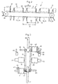
Figur 3- einen Querschnitt,
- Figur 4
- eine detailliertere Seitenansicht eines Teils der Einrichtung, und
Figuren 5 und 6- Draufsichten auf einen Ausschnitt.
- Figure 1
- a schematic perspective view of the device,
- Figure 2
- a schematic side view,
- Figure 3
- a cross section,
- Figure 4
- a more detailed side view of part of the device, and
- Figures 5 and 6
- Top views of a section.
Die in Figur 1 schematisch dargestellte Fördereinrichtung 1
dient zur Zufuhr von Produkten 2 (Figur 2), z.B. von Gruppen
hochkant gestellter Biscuits, zu einer bloss angedeuteten
Verpackungsmaschine 3. Die Verpackungsmaschine kann eine
Schlauchbeutel-Verpackungsmaschine z.B. gemäss EP-B-399
848 sein.
Die Verpackungsmaschine 3 hat
eine Vorratsrolle 4 von Einschlagmaterialfolie 5. Am stromabwärtigen
Ende, der Ausgangsstation 6 der Arbeitsstrecke 7
der Einrichtung 1 werden die Produkte 2 von der Folie 5 umhüllt.
In Förderrichtung A stromabwärts der Ausgangsstation
6 werden die Längsränder 8 der Folie 5 durch Siegel- und
Transporträder 9 miteinander versiegelt, so dass ein
Schlauch um die voneinander beabstandeten Produkte 2 gebildet
wird. Die Räder 9 werden durch einen Motor 10 angetrieben.
Der Motor 10 ist mit einem Drehwinkelgeber 11 verbunden.Stromabwärts
der Räder 9 erfolgt durch nicht dargestellte
Quersiegelbacken mit Trennmessern die Endversiegelung
und Abtrennung in einzelne Packungen. The
Die Einrichtung 1 umfasst zwei zueinander parallele Förderketten
15, 16. Die Ketten 15, 16 sind an der Ausgangsstation
6 um zwei koaxiale, gleich grosse Kettenräder 17, 18 geführt.
Die Räder 17, 18 sind durch separate Servomotoren
19, 20 angetrieben, welche je einen Drehwinkel-Inkrementalgeber
21, 22 aufweisen. Die Geber 21, 22 sind mit einer
Steuereinrichtung 23 verbunden, welche die Motoren 19, 20
bezüglich Drehzahl und Drehwinkel sowie den Motor 10 und
den nachgeschalteten, nicht dargestellten Motor für die
Quersiegelbacken steuert. Am stromaufwärtigen Ende der Arbeitsstrecke
7 laufen die Ketten 15, 16 über koaxiale Umlenkräder
24.The
An jeder Kette 15, 16 sind auf einem Teil ihres Umfangs,
vorzugsweise etwa auf der Hälfte des Umfangs, Mitnehmer 27,
28 und Gegenhalter 29, 30 befestigt. Pro Kette 15, 16 haben
die Mitnehmer 27, 28 im Abschnitt, in welchem die Ketten
15, 16 bestückt sind, einen regelmässigen Abstand voneinander
entsprechend der Teilung 31. Ebenso ist der Abstand 32
zwischen Mitnehmer 27, 28 und zugehörigem Gegenhalter 29,
30 konstant. Benachbart aber vor der Eingangsstation 36 befindet
sich ein Fühler 37 zum Erfassen des Durchgangs jedes
Mitnehmers 27, 28 und/oder jedes Gegenhalters 29, 30, welche
alle in derselben Vertikalebene umlaufen. Der Fühler 37
ist ebenfalls mit der Steuereinrichtung 23 verbunden. In
der Eingangsstation 36 werden die Produkte 2 z.B. durch einen
Stössel quer zur Transportrichtung A auf die Fördereinrichtung
1 aufgeschoben.On each
Wie aus den Figuren 3 bis 6 hervorgeht, steht von jedem Gelenk
der Ketten 15, 16 ein Zapfen 39, 40 nach aussen, d.h.
gegen die von der anderen Kette 16, 15 abgewandte Seite horizontal
ab. Auf jeweils zwei benachbarten dieser Zapfen
39, 40 sind Mitnehmerkörper 41, 42 sowie die Gegenhalter
29, 30 mit entsprechenden Bohrungen aufgesteckt. Die Mitnehmer
27, 28 sind auf diesen Körpern 41, 42 um Querachsen
43, 44 schwenkbar gelagert. Auf der Aussenseite der Körper
41, 42 ist mit den Achsen 43, 44 ein Hebel 45, 46 starr
verbunden, welcher am freien Ende eine Führungsrolle 47, 48
trägt. Die Hebel 45, 46 sind durch eine nicht dargestellte
Feder so belastet, dass die Rollen 47, 48 auf Führungsbahnen
49, 50 aufliegen, zumindest längs der Arbeitsstrecke 7.
Am Ende der Arbeitsstecke 7 haben die Führungsbahnen 49, 50
eine nicht dargestellte Ansenkung, damit die Mitnehmer 27,
28 in der in der US-A-4,068,756 und der EP-B-399 948 erläuterten
Art nach rückwärts schwenken, um das Produkt 2 bei
der Ausgangsstation 6 nicht in Förderrichtung A zu beschleunigen.As can be seen from FIGS. 3 to 6, each joint stands out
the
Durch Umstecken der Mitnehmerkörper 41, 42 und/oder der Gegenhalter
29, 30 können die Teilung 31 und/oder der Abstand
32 verändert und der Länge der Produkte 2 oder der gewünschten
Quersiegelbreite und Produktedicke angepasst werden.
Im allgemeinen wird dabei das Produkt aus Teilung 31
und Anzahl der Mitnehmer 27, 28 nicht dem Umfang der Ketten
15, 16 entsprechen. Ausserhalb des Arbeitsbereichs 7, d.h.
im unteren Trum 53, 54 der Ketten 15, 16 wird deshalb der
vorderste Mitnehmer 27, 28 der einen Kette 15, 16 vom hintersten
Mitnehmer 28, 27 der anderen Kette 16, 15 einen Abstand
haben, der nicht der Teilung 31 entspricht. Dies wird
jeweils ausgeglichen bevor der vorderste Mitnehmer 27, 28
bzw. Gegenhalter 29, 30 die Eingangsstation 36 erreicht, in
dem der betreffende Motor 21 bzw. 22 entsprechend beschleunigt
und verzögert oder verzögert und beschleunigt wird,
gesteuert durch die Steuereinrichtung 23 anhand der Signale
des Fühlers 37 sowie der Drehwinkelgeber 21, 22 derart,
dass längs der Arbeitsstrecke 7 sämtliche Mitnehmer 27, 28
immer einen konstanten Abstand voneinander entsprechend der
Teilung 31 haben.By repositioning the
Die erfindungsgemässe Einrichtung ist sehr viel einfacher
aufgebaut als die eingangs genannten Einrichtungen, weil
sie keiner zusätzlichen Schleife der Transportketten 15, 16
und keiner Einstellung der Lage der stromaufwärtigen Umlenkräder
24 bedarf. Sie ist sehr flexibel und leicht an
andere Produktabstände und Produktlängen anpassbar. Durch
den einfachen Aufbau ist sie auch betriebssicherer.The device according to the invention is much simpler
built up as the facilities mentioned above, because
they do not have an additional loop of the
In den eingangs genannten Einrichtungen werden die Produkte
2 über die Arbeitsstrecke 7 auf einer geschlitzten Platte
geschoben. Die Mitnehmer 27, 28 und Gegenhalter 29, 30
greifen durch den Schlitz dieser Platte. Bei der erfindungsgemässen
Einrichtung dagegen werden auf die Ketten 15,
16 zwischen den Mitnehmern 27, 28 und den zugehörigen Gegenhaltern
29, 30 zusätzlich Tragelemente 55 mit Tragflächen
56 auf je zwei Zapfen 39, 40 aufgesteckt. Die Tragelemente
55 greifen im Bereich der Tragflächen 56 fingerartig
ineinander (Figuren 5 und 6), so dass auch Abstände 32
überbrückt werden können, welche kein ganzzahliges vielfaches
der Tragelementlänge sind. Durch diese Tragelemente
wird eine sehr schonende Handhabung der Produkte 2 erreicht.In the facilities mentioned above, the
Statt der Ketten 15, 16 eignen sich als Förderelemente z.B.
auch Zahnriemen.Instead of the
Abweichend vom dargestellten Ausführungsbeispiel können
auch zwei separate Fühler 37 für die beiden Ketten 15, 16
angeordnet werden, wobei der eine Fühler 37 nur die Mitnehmer
27 und/oder Gegenhalter 29 der einen Kette 15 und der
andere Fühler 37 nur jene der andern Kette 16 erfasst. Dazu
können die Fühler 37 zum Beispiel Vorsprünge 57, 58 auf den
Tragelementen 55 bzw. den Trägern 59 der Gegenhalter 29
beim Durchgang erfassen, z.B. induktiv oder lichtoptisch.
Zur Synchronisation der Motoren 21, 22 mit dem Motor 10
kann letzterer zusätzlich einen Drehwinkel-Inkrementalgeber
11 aufweisen, der mit der Steuereinrichtung 23 verbunden
ist.Deviating from the illustrated embodiment can
also two
Wie aus Figuren 1 und 2 hervorgeht, kann das vorderste Element
der Gruppe von Mitnehmern 27, 28 und Gegenhaltern 29,
30 einer Kette 15, 16 entweder ein Mitnehmer 27, 28 oder
ein Gegenhalter 29, 30 sein. Dadurch kann die auszugleichende
Teilungsabweichung gering gehalten werden. Die maximal
auszugleichende Teilungsabweichung entspricht dann weniger
als der Hälfte der Teilung. Um einen schonenden Betrieb
zu erreichen, werden die beim Teilungsausgleich erforderlichen
Beschleunigungen und Verzögerungen minimiert.As can be seen from Figures 1 and 2, the foremost element
the group of
Claims (10)
- Feed device for a packing machine (3), including two endless conveying elements (15, 16) that circulate adjacent to one another at least along an operating path (7) between an initial station (36) and an end station (6), the conveying elements being driven by separate drives (19, 20), wherein pushers (27, 28) are spaced with a uniform, settable interval (31) over only a portion of the length of each conveying element (15, 16), and wherein a control device (23) is provided for controlling the drives (19, 20) such that the front pusher (27, 28) of the one conveying element (15, 16) follows the back pusher (28, 27) of the other conveying element (16, 15) with the spacing of the interval (31) in the region of the initial station (36).
- Device according to claim 1, wherein the pushers (27, 28) of the two conveying elements (15, 16) are disposed in virtually the same plane.
- Device according to claim 1 or 2, wherein the conveying elements are chains (15, 16), and the pushers (27, 28) are secured to pusher bodies (41, 42) inserted onto pins (39, 40) that project transversely from the chains (15, 16).
- Device according to claim 3, wherein the pushers (27, 28) are seated on the pusher body (41, 42) so as to pivot about transverse shafts (39, 40).
- Device according to one of claims 1 through 4, wherein each conveying element (15, 16) has at least three pushers (27, 28).
- Device according to one of claims 1 through 5, wherein the rpm of the one drive (19, 20) is uniform, provided that at least one of the pushers (27, 28) of the conveying element (15, 16) that is driven with this drive (21, 22) is disposed in the region of the operating path (7), and that this drive (19, 20) drives non-uniformly when the front pusher (27, 28) approaches to region of the initial station (36).
- Device according to one of claims 1 through 6, wherein the conveying elements (15, 16) are respectively diverted on at least one side around a deflecting wheel (17, 18), and the two deflecting wheels (17, 18) are coaxial and are connected to the drives (19, 20).
- Device according to one of claims 1 through 7, wherein the drives (19, 20) are AC-synchronous motors (AC servo motors).
- Device according to one of claims 1 through 8, wherein the drives (19, 20) have incremental resolvers (21, 22), and a position sensor (37) for the pushers (27, 28) is preferably disposed near, but in front of, the initial station (36), in the region of the circulating path of the pushers (27, 28), with the position detector (37) and the incremental resolver (21, 22) being connected to the control device (23), which controls the drives (19, 20).
- Device according to one of claims 1 through 9, wherein the conveying elements (15, 16) can additionally have inserted support elements (55) having a support surface (56) for supporting the products (2) to be conveyed.
Applications Claiming Priority (3)
| Application Number | Priority Date | Filing Date | Title |
|---|---|---|---|
| CH174195 | 1995-06-13 | ||
| CH1741/95 | 1995-06-13 | ||
| PCT/CH1996/000225 WO1996041760A1 (en) | 1995-06-13 | 1996-06-12 | Feed device for a packaging machine |
Publications (2)
| Publication Number | Publication Date |
|---|---|
| EP0833791A1 EP0833791A1 (en) | 1998-04-08 |
| EP0833791B1 true EP0833791B1 (en) | 1999-04-21 |
Family
ID=4217501
Family Applications (1)
| Application Number | Title | Priority Date | Filing Date |
|---|---|---|---|
| EP96919522A Expired - Lifetime EP0833791B1 (en) | 1995-06-13 | 1996-06-12 | Feed device for a packaging machine |
Country Status (6)
| Country | Link |
|---|---|
| US (1) | US6024207A (en) |
| EP (1) | EP0833791B1 (en) |
| JP (1) | JPH11507614A (en) |
| AU (1) | AU5808596A (en) |
| DE (1) | DE59601723D1 (en) |
| WO (1) | WO1996041760A1 (en) |
Cited By (1)
| Publication number | Priority date | Publication date | Assignee | Title |
|---|---|---|---|---|
| DE10020607A1 (en) * | 2000-04-27 | 2001-10-31 | Iwk Verpackungstechnik Gmbh | Transfer device in a packaging machine |
Families Citing this family (15)
| Publication number | Priority date | Publication date | Assignee | Title |
|---|---|---|---|---|
| US6260690B1 (en) * | 1996-02-23 | 2001-07-17 | Bowe Systec Ag | Transport and gathering system |
| US6286290B1 (en) | 1998-05-26 | 2001-09-11 | Sig Pack Systems Ag | Conveyor apparatus for depositing products in groups into containers |
| DK1112933T3 (en) * | 1999-12-29 | 2006-09-18 | Aries Packaging | System for transporting objects |
| JP2001240236A (en) | 2000-03-01 | 2001-09-04 | Shikoku Kakoki Co Ltd | Conveyor |
| JP2002002622A (en) * | 2000-06-26 | 2002-01-09 | Toyo Jidoki Co Ltd | Device for continuously feeding container |
| EP1215122A1 (en) | 2000-12-13 | 2002-06-19 | SIG Pack Systems AG | Conveyor device for making and loading groups of containers |
| EP1359099A3 (en) | 2002-04-18 | 2003-11-19 | SIG Pack Systems AG | Method and apparatus for transferring of unit products into containers |
| CN100403867C (en) * | 2004-12-30 | 2008-07-16 | 技嘉科技股份有限公司 | Feeding track |
| US8336700B2 (en) * | 2009-04-08 | 2012-12-25 | Ima North America, Inc. | Transport system for moving a plurality of containers through a plurality of work stations |
| JP5985199B2 (en) * | 2012-02-15 | 2016-09-06 | 株式会社ブリヂストン | Pneumatic tires for motorcycles |
| DE102012017092B4 (en) * | 2012-08-29 | 2014-08-21 | TRüTZSCHLER GMBH & CO. KG | Feeding system for textile processing machines |
| JP6040406B2 (en) * | 2013-05-10 | 2016-12-07 | ゼネラルパッカー株式会社 | Gas filling and packaging method and packaging machine |
| US9821961B2 (en) * | 2015-06-01 | 2017-11-21 | Illinois Tool Works Inc. | Adjustable conveying device |
| IT201600097558A1 (en) * | 2016-09-29 | 2018-03-29 | Bucci Automations S P A | GROUPING STATION PRODUCTS FOR HYGIENIC AND SANITARY PRODUCTS |
| EP3428079B1 (en) * | 2017-07-14 | 2019-12-25 | MULTIVAC Sepp Haggenmüller SE & Co. KG | Deep draw packaging machine with flexible package support |
Family Cites Families (9)
| Publication number | Priority date | Publication date | Assignee | Title |
|---|---|---|---|---|
| FR1393472A (en) * | 1964-02-11 | 1965-03-26 | Materiel Ceramique Moderne | Device for aligning and moving en bloc, until a chosen point, a determined number of products arriving one by one on this device |
| CH412708A (en) * | 1964-08-11 | 1966-04-30 | Sig Schweiz Industrieges | Conveyor device on a processing machine |
| CH605352A5 (en) * | 1975-11-24 | 1978-09-29 | Sig Schweiz Industrieges | |
| SE413494B (en) * | 1977-05-17 | 1980-06-02 | Wikings Mek Verk | TRANSPORT DEVICE FOR GROUPS OF FORMAL BETWEEN AN INPUT AND OUTPUT STATION |
| US4768642A (en) * | 1987-06-16 | 1988-09-06 | Kimberly-Clark Corporation | Multiple conveyors with overlapping material handling device paths |
| ES2062484T3 (en) * | 1989-05-24 | 1994-12-16 | Sig Schweiz Industrieges | A PROCEDURE AND A DEVICE FOR THE CONTINUOUS MANUFACTURE OF PACKAGING. |
| US5127209A (en) * | 1990-11-15 | 1992-07-07 | Kimberly-Clark Corporation | Multi-purpose stacker with overlapping material handling devices |
| US5337887A (en) * | 1993-02-19 | 1994-08-16 | R. A. Jones & Co. Inc. | Quick-disconnect lug for a cartoning machine |
| US5560473A (en) * | 1994-11-07 | 1996-10-01 | The Paxall Group, Inc. | Drive mechanism for a carton conveyor |
-
1996
- 1996-06-12 US US08/945,443 patent/US6024207A/en not_active Expired - Lifetime
- 1996-06-12 EP EP96919522A patent/EP0833791B1/en not_active Expired - Lifetime
- 1996-06-12 WO PCT/CH1996/000225 patent/WO1996041760A1/en active IP Right Grant
- 1996-06-12 JP JP9502453A patent/JPH11507614A/en active Pending
- 1996-06-12 AU AU58085/96A patent/AU5808596A/en not_active Abandoned
- 1996-06-12 DE DE59601723T patent/DE59601723D1/en not_active Expired - Lifetime
Cited By (1)
| Publication number | Priority date | Publication date | Assignee | Title |
|---|---|---|---|---|
| DE10020607A1 (en) * | 2000-04-27 | 2001-10-31 | Iwk Verpackungstechnik Gmbh | Transfer device in a packaging machine |
Also Published As
| Publication number | Publication date |
|---|---|
| US6024207A (en) | 2000-02-15 |
| JPH11507614A (en) | 1999-07-06 |
| DE59601723D1 (en) | 1999-05-27 |
| EP0833791A1 (en) | 1998-04-08 |
| AU5808596A (en) | 1997-01-09 |
| WO1996041760A1 (en) | 1996-12-27 |
Similar Documents
| Publication | Publication Date | Title |
|---|---|---|
| EP0833791B1 (en) | Feed device for a packaging machine | |
| DE69908370T2 (en) | DEVICE AND METHOD FOR CONVEYING OBJECTS IN THE FORM OF CYLINDRICAL ROLLS | |
| EP2143673B1 (en) | Transport device for feeding articles into a packaging machine | |
| DE60311778T2 (en) | RETRACTABLE TRANSFER DEVICE FOR A DOSING DEVICE | |
| EP2826735B1 (en) | Adjustable storage section of a conveyor device and method for the intermediate storage of items | |
| DE3842964A1 (en) | DEVICE FOR FORMING GROUPS OF ITEMS, IN PARTICULAR FOR AUTOMATIC PACKING ROADS | |
| EP0885821B1 (en) | Apparatus for aligning products having an approximately rectangular cross-section | |
| DE69720125T2 (en) | Transport unit for products | |
| EP1868925B1 (en) | Feeding device for a packaging machine | |
| EP2212225A1 (en) | Multiplex grouping device | |
| EP2799348B1 (en) | Method for grouping articles in article bars and grouping device and packaging machine comprising same | |
| DE3724693A1 (en) | DEVICE FOR TRANSFERRING OBJECTS INTO A CONVEYOR DEVICE OF A PACKING MACHINE | |
| EP0752383B1 (en) | Device for separating flat stacked objects | |
| EP0619229B1 (en) | Device for dividing flat products on several exit columns | |
| DE4105273A1 (en) | DEVICE FOR STACKING PACKING UNITS | |
| EP1216939A1 (en) | Device for conveying objects and including an accumulating buffer | |
| DE1506987C3 (en) | Transport system for transferring objects from a first to a second transport device | |
| EP0608861A2 (en) | Method and apparatus for feeding sensitive objects to a processing machine | |
| EP2723659B2 (en) | Device and method for grouping articles | |
| DE102010050035A1 (en) | Transport section for influencing disordered mass flow of separate articles i.e. beverage containers, has guide elements projecting into article flow and moved in conveyor direction of articles against force in direction of sides of plane | |
| EP1089926B1 (en) | Conveyor section arrangement for containers being filled with items or bulk material at a filling station | |
| DE2504264A1 (en) | Storage equipment for vertical moved container - has main conveying track for driving container and storage conveying track | |
| EP1238910A1 (en) | Method and apparatus for packaging elongate objects | |
| DE8214126U1 (en) | DEVICE FOR AUTOMATICALLY MOVING ROD-SHAPED OBJECTS, IN PARTICULAR LATERS OR FRAME STRIPS | |
| EP1144282A1 (en) | Picking store for piece goods |
Legal Events
| Date | Code | Title | Description |
|---|---|---|---|
| PUAI | Public reference made under article 153(3) epc to a published international application that has entered the european phase |
Free format text: ORIGINAL CODE: 0009012 |
|
| 17P | Request for examination filed |
Effective date: 19971212 |
|
| AK | Designated contracting states |
Kind code of ref document: A1 Designated state(s): DE GB IT NL |
|
| GRAG | Despatch of communication of intention to grant |
Free format text: ORIGINAL CODE: EPIDOS AGRA |
|
| 17Q | First examination report despatched |
Effective date: 19980630 |
|
| GRAG | Despatch of communication of intention to grant |
Free format text: ORIGINAL CODE: EPIDOS AGRA |
|
| GRAH | Despatch of communication of intention to grant a patent |
Free format text: ORIGINAL CODE: EPIDOS IGRA |
|
| RAP1 | Party data changed (applicant data changed or rights of an application transferred) |
Owner name: SIG PACK SYSTEMS AG |
|
| GRAH | Despatch of communication of intention to grant a patent |
Free format text: ORIGINAL CODE: EPIDOS IGRA |
|
| GRAA | (expected) grant |
Free format text: ORIGINAL CODE: 0009210 |
|
| AK | Designated contracting states |
Kind code of ref document: B1 Designated state(s): DE GB IT NL |
|
| GBT | Gb: translation of ep patent filed (gb section 77(6)(a)/1977) |
Effective date: 19990421 |
|
| REF | Corresponds to: |
Ref document number: 59601723 Country of ref document: DE Date of ref document: 19990527 |
|
| PLBE | No opposition filed within time limit |
Free format text: ORIGINAL CODE: 0009261 |
|
| STAA | Information on the status of an ep patent application or granted ep patent |
Free format text: STATUS: NO OPPOSITION FILED WITHIN TIME LIMIT |
|
| 26N | No opposition filed | ||
| REG | Reference to a national code |
Ref country code: GB Ref legal event code: IF02 |
|
| PGFP | Annual fee paid to national office [announced via postgrant information from national office to epo] |
Ref country code: NL Payment date: 20120628 Year of fee payment: 17 |
|
| PGFP | Annual fee paid to national office [announced via postgrant information from national office to epo] |
Ref country code: GB Payment date: 20130620 Year of fee payment: 18 |
|
| PGFP | Annual fee paid to national office [announced via postgrant information from national office to epo] |
Ref country code: DE Payment date: 20130828 Year of fee payment: 18 |
|
| REG | Reference to a national code |
Ref country code: NL Ref legal event code: V1 Effective date: 20140101 |
|
| PGFP | Annual fee paid to national office [announced via postgrant information from national office to epo] |
Ref country code: IT Payment date: 20130622 Year of fee payment: 18 |
|
| PG25 | Lapsed in a contracting state [announced via postgrant information from national office to epo] |
Ref country code: NL Free format text: LAPSE BECAUSE OF NON-PAYMENT OF DUE FEES Effective date: 20140101 |
|
| REG | Reference to a national code |
Ref country code: DE Ref legal event code: R119 Ref document number: 59601723 Country of ref document: DE |
|
| GBPC | Gb: european patent ceased through non-payment of renewal fee |
Effective date: 20140612 |
|
| REG | Reference to a national code |
Ref country code: DE Ref legal event code: R119 Ref document number: 59601723 Country of ref document: DE Effective date: 20150101 |
|
| PG25 | Lapsed in a contracting state [announced via postgrant information from national office to epo] |
Ref country code: IT Free format text: LAPSE BECAUSE OF NON-PAYMENT OF DUE FEES Effective date: 20140612 Ref country code: DE Free format text: LAPSE BECAUSE OF NON-PAYMENT OF DUE FEES Effective date: 20150101 |
|
| PG25 | Lapsed in a contracting state [announced via postgrant information from national office to epo] |
Ref country code: GB Free format text: LAPSE BECAUSE OF NON-PAYMENT OF DUE FEES Effective date: 20140612 |