EP1173045B1 - Elektrische Heizvorrichtung mit Schutzschaltung - Google Patents
Elektrische Heizvorrichtung mit Schutzschaltung Download PDFInfo
- Publication number
- EP1173045B1 EP1173045B1 EP01113987A EP01113987A EP1173045B1 EP 1173045 B1 EP1173045 B1 EP 1173045B1 EP 01113987 A EP01113987 A EP 01113987A EP 01113987 A EP01113987 A EP 01113987A EP 1173045 B1 EP1173045 B1 EP 1173045B1
- Authority
- EP
- European Patent Office
- Prior art keywords
- switching
- heating
- heating elements
- heating device
- mosfet
- Prior art date
- Legal status (The legal status is an assumption and is not a legal conclusion. Google has not performed a legal analysis and makes no representation as to the accuracy of the status listed.)
- Expired - Lifetime
Links
- 238000010438 heat treatment Methods 0.000 title claims description 96
- 239000004065 semiconductor Substances 0.000 claims description 16
- 230000001681 protective effect Effects 0.000 claims description 8
- 230000007547 defect Effects 0.000 description 9
- 230000002950 deficient Effects 0.000 description 7
- 239000000498 cooling water Substances 0.000 description 3
- 230000001419 dependent effect Effects 0.000 description 3
- 238000010586 diagram Methods 0.000 description 3
- 230000000694 effects Effects 0.000 description 2
- 239000007788 liquid Substances 0.000 description 2
- 238000010792 warming Methods 0.000 description 2
- 230000004913 activation Effects 0.000 description 1
- 230000008878 coupling Effects 0.000 description 1
- 238000010168 coupling process Methods 0.000 description 1
- 238000005859 coupling reaction Methods 0.000 description 1
- 230000010354 integration Effects 0.000 description 1
- 238000013021 overheating Methods 0.000 description 1
- 238000004513 sizing Methods 0.000 description 1
Images


Classifications
-
- H—ELECTRICITY
- H05—ELECTRIC TECHNIQUES NOT OTHERWISE PROVIDED FOR
- H05B—ELECTRIC HEATING; ELECTRIC LIGHT SOURCES NOT OTHERWISE PROVIDED FOR; CIRCUIT ARRANGEMENTS FOR ELECTRIC LIGHT SOURCES, IN GENERAL
- H05B1/00—Details of electric heating devices
- H05B1/02—Automatic switching arrangements specially adapted to apparatus ; Control of heating devices
- H05B1/0202—Switches
- H05B1/0205—Switches using a fusible material
Definitions
- the present invention relates to an electric heater according to the features of the preamble of the claim 1.
- GB 2076056 A describes a heating device with a Number of MOSFETs connected in parallel, their load paths respectively between a supply potential and a reference potential are switched. The overall arrangement is through a fuse hedged.
- the MOSFETs are controlled by a drive circuit controlled, this drive circuit a Temperature control circuit which turns off the MOSFET, when the temperature is above a predetermined value Temperature has risen.
- the aim of the present invention is to provide a heating device for To provide, which in the case of the defect, or the Overheating, one of the switching and heating elements used safely shuts off.
- the heater according to the invention at least two switching and heating elements, each with a control terminal and a load path, wherein the load paths the switching and heating elements are connected in parallel.
- the inventive Heating device also has a protection circuit on, at the control terminal at least one the switching elements is connected, and wherein the protection circuit is formed to the connected switching element in accordance with the temperature of at least one of the others Turn on switching elements.
- Is in the heater according to the invention one of Switching and heating elements defective, it is controlled by the protection circuit of at least one of the other switching and Heating elements conductive, preferably all switching and Heating elements controlled by the protection circuit conductive.
- the control of the connected to the protection circuit Switching and heating elements takes place in such a way that these Switching and heating elements have such a high current consumption, that connected in series with the switching and heating elements Fuse unit triggers and the power supply the entire heater stops.
- switching and heating elements found in the inventive Heating device preferably semiconductor devices, such as MOSFET, application.
- these semiconductor devices via their respective control connection (gate connection) be controlled so that they have a variable, medium- to high-impedance, have on-resistance, so that over their load path (drain-source path) even with correspondingly large voltages, a variable current flows and so a controllable heating of the device occurs which is desired and for heating air or Liquids, such as the cooling water of a car used becomes.
- the area in which the on-resistance by a suitable drive during heating can be varied can, is of the desired heating capacity and sizing of the semiconductor device dependent.
- the protection circuit must be connected to at least at the defect one of the switching and heating elements driven to become. Or only some of them can be connected in parallel Switching and heating elements to the protection circuit for control be connected. It should be noted that it is off Safety reasons may be appropriate, in case of failure so to control as many switching and heating elements as possible the largest possible flow of current through the fuse unit, and thus to trigger a safe release of the fuse.
- the protective circuit of the heater is at least one Temperature controlled switch provided between a Node for a supply potential and a common Node is interconnected.
- the control terminals of the through Protection circuit controllable switching elements are doing coupled to the common node.
- the temperature-controlled Switch is designed such that it when exceeded a predetermined temperature at one of the switching and heating elements, with which the temperature controlled switch in thermal connection stands, the common node of the Protection circuit to which the control terminals of Schuund Switching elements are coupled to the value of a supply potential which ensures that the connected switching and heating elements sufficient cause high current consumption at which the fuse triggers.
- a temperature-controlled Switch with each of the heating and switching elements thermally couple to make sure that at a Defective of each one of the heating and switching elements the other switching and heating elements are conductive and the Trigger fuse.
- the temperature-controlled switches are preferably thyristors, one of which is connected to one of the load paths of the switching and heating element is connected and whose other connection is connected to the common node is.
- the preferably used temperature-controlled Thyristor ignites when a design-related temperature is reached, the voltage drop across the conductive thyristor is low, so the control terminals of the non-defective Switching and heating elements are safely controlled.
- the temperature controlled switch is preferably in the associated one Switching and heating integrated, with a monolithic integration of the switching and heating element and the temperature-controlled switch in a semiconductor body are formed.
- the temperature controlled switch and the associated switching and heating element can also be called so-called Chip-on-chip arrangement may be formed in which a chip with the switching and heating element and a chip with the temperature-controlled Switches arranged one above the other and thermal are conductively connected. With both solutions one reaches one optimal and defined heat coupling.
- the heater in accordance with the present invention using below of power MOSFET described as switching and heating elements.
- the gate terminal of a MOSFET fulfills the function a control terminal, the drain-source path of the MOSFET provides the load path of the MOSFET formed by the MOSFET Switching and heating element.
- Figures 1 to 3 are n-channel MOSFET used as switching and heating elements.
- the invention is of course also related to p-channel MOSFET usable, in which case supply voltages polarity reversal and the polarity of poling-dependent components, such as For example, diodes, must be reversed.
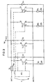
- Fig. 1 is a first embodiment of an inventive Heating device using power MOSFET T1, T2, Tn shown.
- the drain-source paths D-S of MOSFETs T1, T2, Tn are connected in parallel, this parallel connection in series with a fuse unit Si, for example a fuse or a magnetic fuse, is switched.
- the series connection of fuse unit Si and the parallel-connected MOSFET T1, T2, Tn via connection terminals AK1, AK2 to a supply voltage V connected.
- the MOSFETs T1, T2, Tn are usually spatially distributed in the medium to be heated, arranged around a better distribution of the votes by the heater Heat, for example in an air supply or a liquid container, to effect. It is also conceivable that the individual MOSFET independently for heating different Media operated.
- the essential Request to the drive circuit AS is that they the MOSFET T1, T2, Tn for the heating operation such that they have a medium to high on-resistance, such that when a voltage is applied across their drain-source paths D-S a medium to low current flows and a large part of the electrical power provided to the by the drive circuit AS controlled MOSFET T1, T2, Tn is converted into heat.
- the heating device has a protective device SC, wherein output terminals A1, A2, A3 of the protection device each to the gate terminal G of one of the MOSFET T1, T2, Tn is connected.
- the protection circuit SC points Further, one of the number of MOSFETs T1, T2, Tn corresponding Number of temperature-controlled switch S1, S2, Sn on, the thermally coupled to one of each of the MOSFETs T1, T2, Tn is.
- the temperature-controlled switches S1, S2, Sn are in the embodiment according to Figure 2 as a temperature-controlled Thyristors are formed, each between a node N11 for supply potential and a common node N2 of the protection circuit SC are connected.
- the node N11 for supply potential is in the embodiment according to Fig.
- An of the protection circuit Sc is a series connection of a resistor R1, R2, Rn and a diode D1, D2, Dn connected, which the Task, the gate terminals G of the MOSFET T1, T2, Tn to protect against excessive drive levels.
- Heating device according to FIG. 1 will now be assumed that the MOSFET T1 is driven by the drive circuit AS is to heat a medium in which it is housed, it is further assumed that in the MOSFET T1 a Defect occurs, resulting in a strong heating of this semiconductor device leads. Is this a conditional by the type Temperature threshold of the temperature-controlled thyristor Reaches S1, then ignites this thyristor S1 and sets the common Node N2 approximately to the value of the at the Node N11 applied supply potential.
- the MOSFET T2, Tn are doing via the series connection of the diode D2 and the Resistor R2, or the diode Dn and the resistor Rn, driven, taking resistors R2, Rn into consideration of the voltage applied to the common node N2 potential such are selected at the gate terminals T2, Tn sufficiently high potential is applied to over the load paths D-S this MOSFET T2, Tn cause a large current flow, or the load paths of the MOSFET T2, Tn through.
- the resistor R1 of the MOSFET T2 in case of failure of one of the other two MOSFET T2, Tn.
- the fuse unit Si is designed to control the current flow between the terminals AK1, AK1 of the supply voltage source to limit. If this current rises above one by the type of fuse unit Si conditional value, so the fuse unit triggers Si and interrupts the Power supply to the MOSFET T1, T2, Tn.
- the inventive Heating device releases the fuse unit Si in said Use case when the MOSFET T2, Tn driven conduct well through the temperature-controlled thyristor S2 and so a large current flow through the fuse unit Si cause. This is regardless of whether the two are not defective MOSFET T2, Tn before the defect of the MOSFET T1 by the Control circuit AS were also driven to heat, or if they were switched off.
- the inventive Heating device makes use of that power MOSFET T1, T2, Tn operated with different power consumption can be.
- the power MOSFET T1, T2, Tn so controlled via the drive circuit AS, that they have a low power consumption, with the maximum by the fuse unit Si permissible current and the received by the MOSFETs T1, T2, Tn during the heating operation Currents are coordinated so that the Fuse unit Si does not trip even if all parallel switched MOSFET T1, T2, Tn by the drive circuit AS are controlled for heating operation.
- the power MOSFET T1, T2, Tn can also be controlled in this way that they have a large power input to the fuse unit Si trigger.
- the power MOSFETs T1, T2, Tn are preferably dimensioned so that already one through the Protection circuit SC driven conductive MOSFET T1; T2; Tn is enough to trigger the fuse unit Si.
- temperature-controlled switches S1, S2, Sn are in addition to temperature-controlled Thyristors of course any further temperature-controlled switch can be used, which at Switching over a predefinable temperature switch or one have low line resistance to not defective To control MOSFET.
- the drive circuit AS must be so be trained that in case of failure, an increase in the Potentials at the gate terminals of the power MOSFET through the protection circuit SC allows to enable conduct the power MOSFET well and trigger the fuse Si.
- Fig. 2 shows a further embodiment of the erfindungsgemä ⁇ en Heater in which the protection circuit SC only an output terminal A, to which all MOSFET T1, T2, Tn are connected in common. Between the common Node N2 and the output terminal A is in corresponding As in Fig. 1, a series circuit of a Diode D4 and a resistor R4 connected to the gate terminals G of the power MOSFET T1, T2, Tn against too high drive potentials to protect.
- the operation of the in Fig. 2 illustrated heater corresponds to that shown in Fig. 1 and heating device described above.
- Fig. 3 shows a further embodiment of an inventive Heating device, which differs from those in the figures 1 and 2 heaters illustrated differs by that not for each of the parallel-connected power MOSFET T1, T4, T5, Tn thermally coupled temperature controlled Switch S1, S4, Sn is provided. Only the Power MOSFETs T1, T4, Tn have such a temperature-controlled Switch S1, S4, Sn on while for the MOSFET T5 no such security element is provided. Further, in Fig. 3, not every one of the power MOSFETs can be controlled by the protection circuit. Such is the power MOSFET Although T4 to the drive circuit AS for heating but not connected to the protection circuit. in the With regard to the above-described operation of the Heating device according to the invention means this for the embodiment according to Fig.
- FIG. 3 is intended to illustrate that depending on the applications not for everyone Switching and heating units Temperature protection units provided and not all switching and heating units have to be controlled by the protection circuit, to trigger the fuse unit Si.
- the temperature-controlled Thyristors S1, S4, Sn differently than in the embodiments according to Figures 1 and 2 not to the Drain terminals D of the power MOSFET T1, T4, T5, Tn but to a further node N12 at which a drive potential Va is present, connected.
Landscapes
- Semiconductor Integrated Circuits (AREA)
- Control Of Resistance Heating (AREA)
Description
- Figur 1:
- Schaltbild einer ersten Ausführungsform einer erfindungsgemäßen Heizvorrichtung;
- Figur 2:
- Schaltbild einer zweiten Ausführungsform einer erfindungsgemäßen Heizvorrichtung.
- Figur 3:
- Schaltbild einer dritten Ausführungsform einer erfindungsgemäßen Heizvorrichtung.
- A
- Ausgangsklemme
- A1, A2, An
- Ausgangsklemmen
- AK1, AK2
- Anschlussklemmen
- AS
- Ansteuerschaltung
- D
- Drain-Anschluss
- D1, D2, Dn
- Dioden
- D4, D5
- Dioden
- G
- Gate-Anschluss
- N11, N12
- Knoten für Ansteuerpotential
- N2
- Gemeinsamer Knoten
- R1, R2, Rn
- Widerstände
- R4, R5,
- Widerstände
- S
- Source-Anschluss
- S1, S2, S4
- Temperaturgesteuerte Schalter
- Sn
- Temperaturgesteuerte Schalter
- Si
- Sicherungseinheit
- T1, T2, Tn
- Leistungs-MOSFET
- T4, T5
- Leistungs-MOSFET
- V
- Versorgungsspannung
- Vsi
- Spannung über der Sicherungseinheit
Claims (9)
- Elektrische Heizvorrichtung, die folgende Merkmale aufweist:gekennzeichnet durch folgendes weiteres Merkmal:wenigstens zwei Schalt- und Heizelemente (T1, T2, Tn; T1, T4, T5, Tn), die jeweils eine Ansteuerklemme (G) und eine Laststrecke (D-S) aufweisen, wobei die Laststrecken (D-S) der wenigstens zwei Schalt- und Heizelemente (T1, T2, Tn; T1, T4, T5, Tn) parallel geschaltet sind,eine Sicherungseinheit (Si), die in Reihe zu den Laststrecken (D-S) der Schalt- und Heizelemente (T1, T2, Tn; T1, T4, T5, Tn) geschaltet ist, wobei die Reihenschaltung an eine Versorgungsspannung (V) angeschlossen ist,eine an den Steueranschluss (G) wenigstens eines der Schaltund Heizelemente (T1, T2, Tn; T1, T5, Tn) angeschlossene Schutzschaltung (SC) zum Einschalten des wenigstens einen angeschlossenen Schalt- und Heizelements (T1, T2, Tn; T1, T5, Tn) nach Maßgabe der Temperatur an wenigstens einem der Schalt- und Heizelemente (T1, T2, Tn; T1, T4, Tn) derart, dass das wenigstens eine angeschlossene Schalt- und Heizelement (T1, T2, Tn; T1, T5, Tn) eine so hohe Stromaufnahme aufweist, dass die Sicherungseinheit (Si) auslöst.
- Heizvorrichtung nach Anspruch 1, bei der die Schutzschaltung (SC) an die Steueranschlüsse (G) aller Schalt- und Heizelemente (T1, T2, Tn) angeschlossen ist.
- Heizvorrichtung nach Anspruch 1 oder 2, bei der die Temperaturen an allen Schalt- und Heizelementen (T1, T2, Tn) bei der Ansteuerung der an die Schutzschaltung (SC) angeschlossenen Schalt- und Heizelemente (T1, T2, Tn) berücksichtigt werden.
- Heizvorrichtung nach einem der vorangehenden Ansprüche , bei der die Schutzschaltung wenigstens einen temperaturgesteuerten Schalter (S1, S2, Sn; S1, S4, Sn) aufweist, der zwischen einem Knoten (N1; N11) für ein Versorgungspotential und einem gemeinsamen Knoten (N2), an den die Steueranschlüsse (G) der durch die Schutzschaltung ansteuerbaren Schaltelemente (T1, T2, Tn; T1, T4, T5, Tn) gekoppelt sind, verschaltet ist und der an eines der Schalt- und Heizelemente (T1, T2, Tn; T1, T4, Tn) thermisch gekoppelt ist.
- Heizvorrichtung nach Anspruch 4, bei der an jedes der Schalt- und Heizelemente (T1, T2, Tn) ein temperaturgesteuerter Schalter thermisch gekoppelt ist.
- Heizvorrichtung nach Anspruch 4 oder 5, bei der die Steueranschlüsse (G) der durch die Schutzschaltung (SC) ansteuerbaren Schalt- und Heizelemente (T1, T2, Tn; T1, T5, Tn) über Dioden (D1, D2, Dn; D1, D5, Dn) an den gemeinsamen Knoten (N2) gekoppelt sind.
- Heizvorrichtung nach einem der vorangehenden Ansprüche, bei der die Schalt- und Heizelemente (T1, T2, Tn; T1, T4, T5, Tn) Halbleiterschaltelemente, insbesondere Transistoren sind.
- Heizvorrichtung nach einem der vorangehenden Ansprüche, bei der die temperaturgesteuerten Schalter (S1, S2, Sn; S1, S4, Sn) jeweils an einen Anschluss (D) der Laststrecke (D-S) eines Schalt- und Heizelements (T1, T2, Tn; T1, T4, Tn) angeschlossen sind.
- Heizvorrichtung nach einem der vorangehenden Ansprüche, bei dem der temperaturgesteuerte Schalter (S1, S2, Sn; S1, S4, Sn) ein Thyristor ist.
Applications Claiming Priority (2)
| Application Number | Priority Date | Filing Date | Title |
|---|---|---|---|
| DE10034063 | 2000-07-13 | ||
| DE10034063A DE10034063C2 (de) | 2000-07-13 | 2000-07-13 | Elektrische Heizvorrichtung mit Schutzschaltung |
Publications (3)
| Publication Number | Publication Date |
|---|---|
| EP1173045A2 EP1173045A2 (de) | 2002-01-16 |
| EP1173045A3 EP1173045A3 (de) | 2003-01-22 |
| EP1173045B1 true EP1173045B1 (de) | 2004-08-25 |
Family
ID=7648796
Family Applications (1)
| Application Number | Title | Priority Date | Filing Date |
|---|---|---|---|
| EP01113987A Expired - Lifetime EP1173045B1 (de) | 2000-07-13 | 2001-06-08 | Elektrische Heizvorrichtung mit Schutzschaltung |
Country Status (2)
| Country | Link |
|---|---|
| EP (1) | EP1173045B1 (de) |
| DE (2) | DE10034063C2 (de) |
Family Cites Families (6)
| Publication number | Priority date | Publication date | Assignee | Title |
|---|---|---|---|---|
| US3393870A (en) * | 1966-12-20 | 1968-07-23 | Texas Instruments Inc | Means for controlling temperature rise of temperature stabilized substrates |
| DE2949329A1 (de) * | 1979-12-07 | 1981-06-11 | Siemens AG, 1000 Berlin und 8000 München | Heizbare fluessigkristallzelle |
| GB2076056A (en) * | 1980-05-20 | 1981-11-25 | Lucas Industries Ltd | Fuel heating device |
| DE19733045C1 (de) * | 1997-07-31 | 1998-07-30 | Fahrzeugklimaregelung Gmbh | Elektrische Heizung für ein Kraftfahrzeug |
| DE19744765A1 (de) * | 1997-10-10 | 1999-04-15 | Daimler Chrysler Ag | Schaltungsanordnung und Verfahren zum Betreiben eines Sicherungselements |
| DE19754415A1 (de) * | 1997-12-09 | 1999-06-10 | Wickmann Werke Gmbh | Schutzschaltung |
-
2000
- 2000-07-13 DE DE10034063A patent/DE10034063C2/de not_active Expired - Fee Related
-
2001
- 2001-06-08 DE DE50103377T patent/DE50103377D1/de not_active Expired - Lifetime
- 2001-06-08 EP EP01113987A patent/EP1173045B1/de not_active Expired - Lifetime
Also Published As
| Publication number | Publication date |
|---|---|
| DE50103377D1 (de) | 2004-09-30 |
| EP1173045A3 (de) | 2003-01-22 |
| DE10034063C2 (de) | 2003-10-16 |
| EP1173045A2 (de) | 2002-01-16 |
| DE10034063A1 (de) | 2002-01-31 |
Similar Documents
| Publication | Publication Date | Title |
|---|---|---|
| DE69420327T2 (de) | Halbleiter-Leistungsschaltung | |
| DE102016224706B4 (de) | Gate-Antriebsschaltung für Halbleiterschaltgeräte | |
| DE19824283B4 (de) | Stromsteuerungsschaltkreis | |
| DE102009007790B3 (de) | Treiberchip zum Treiben einer induktiven Last | |
| DE112015001177B4 (de) | Einschaltzustandsstörungs-Erfassungsvorrichtung und Verfahren dafür | |
| DE102006040753B4 (de) | Redundante Stromversorgung mit Diagnosefähigkeit und Schutzbeschaltung | |
| EP3756253B1 (de) | Entladevorrichtung, elektrische einheit und entladeverfahren | |
| DE3490296T1 (de) | Leistungsschalterkreis mit parallelen MOS-Feldeffekttransistoren | |
| DE102014108576B4 (de) | Treiberschaltung mit Miller-Clamping-Funktionalität für Leistungshalbleiterschalter, Leistungshalbleiterschalter und Wechselrichterbrücke | |
| EP0927461B1 (de) | Temperaturgeschütztes elektrisches schalter-bauelement | |
| EP2342824B1 (de) | Vor kurzschluss geschützte halbbrückenschaltung mit halbleiterschaltern | |
| EP1630013B1 (de) | Elektrische Zusatzheizung für Kraftfahrzeuge mit Stromsicherung | |
| DE102005003643B4 (de) | Schaltungsvorrichtung mit einem Strombegrenzer eines Ausgangstransistors | |
| EP0825716B1 (de) | Ansteuerschaltung für ein Feldeffekt gesteuertes Halbleiterbauelement | |
| DE102018129909B4 (de) | Leistungselektronikeinrichtung | |
| EP1173045B1 (de) | Elektrische Heizvorrichtung mit Schutzschaltung | |
| DE102005051004A1 (de) | Temperaturkompensation bei Endstufen | |
| DE10149234A1 (de) | Sicherungsgeschützter Nebenschlußregler und Verfahren zum Schützen eines Nebenschußreglers | |
| EP0393224B1 (de) | Schaltungsanordnung zur Temperaturüberwachung von in einem Halbleiterschaltkreis integrierten Leistungsschalttransistoren | |
| DE102005008100B4 (de) | Redundanzschaltung für in Reihe angeschlossene Dioden | |
| DE102005019709A1 (de) | Endstufe mit Zenerspannungs-Symmetrierung | |
| EP1630923B1 (de) | Steuerschaltung für eine Mehrzahl elektrischer Verbraucher mit einer Absicherung für Halbleiterschalter | |
| EP0496910B1 (de) | Schaltungsanordnung zur Generierung eines Rücksetzsignals | |
| DE19805491C1 (de) | Diodenschaltung mit idealer Diodenkennlinie | |
| DE4428115A1 (de) | Steuergerät mit einer Schaltungsanordnung zum Schutz des Steuergerätes bei Unterbrechung der Steuergerätemasse |
Legal Events
| Date | Code | Title | Description |
|---|---|---|---|
| PUAI | Public reference made under article 153(3) epc to a published international application that has entered the european phase |
Free format text: ORIGINAL CODE: 0009012 |
|
| AK | Designated contracting states |
Kind code of ref document: A2 Designated state(s): AT BE CH CY DE DK ES FI FR GB GR IE IT LI LU MC NL PT SE TR |
|
| AX | Request for extension of the european patent |
Free format text: AL;LT;LV;MK;RO;SI |
|
| PUAL | Search report despatched |
Free format text: ORIGINAL CODE: 0009013 |
|
| AK | Designated contracting states |
Kind code of ref document: A3 Designated state(s): AT BE CH CY DE DK ES FI FR GB GR IE IT LI LU MC NL PT SE TR |
|
| AX | Request for extension of the european patent |
Free format text: AL;LT;LV;MK;RO;SI |
|
| 17P | Request for examination filed |
Effective date: 20030124 |
|
| 17Q | First examination report despatched |
Effective date: 20030311 |
|
| AKX | Designation fees paid |
Designated state(s): DE FR IT |
|
| GRAP | Despatch of communication of intention to grant a patent |
Free format text: ORIGINAL CODE: EPIDOSNIGR1 |
|
| GRAS | Grant fee paid |
Free format text: ORIGINAL CODE: EPIDOSNIGR3 |
|
| GRAA | (expected) grant |
Free format text: ORIGINAL CODE: 0009210 |
|
| AK | Designated contracting states |
Kind code of ref document: B1 Designated state(s): DE FR IT |
|
| REG | Reference to a national code |
Ref country code: IE Ref legal event code: FG4D Free format text: GERMAN |
|
| REF | Corresponds to: |
Ref document number: 50103377 Country of ref document: DE Date of ref document: 20040930 Kind code of ref document: P |
|
| REG | Reference to a national code |
Ref country code: IE Ref legal event code: FD4D |
|
| ET | Fr: translation filed | ||
| PLBE | No opposition filed within time limit |
Free format text: ORIGINAL CODE: 0009261 |
|
| STAA | Information on the status of an ep patent application or granted ep patent |
Free format text: STATUS: NO OPPOSITION FILED WITHIN TIME LIMIT |
|
| 26N | No opposition filed |
Effective date: 20050526 |
|
| PGFP | Annual fee paid to national office [announced via postgrant information from national office to epo] |
Ref country code: IT Payment date: 20150622 Year of fee payment: 15 |
|
| REG | Reference to a national code |
Ref country code: FR Ref legal event code: PLFP Year of fee payment: 16 |
|
| REG | Reference to a national code |
Ref country code: FR Ref legal event code: PLFP Year of fee payment: 17 |
|
| PG25 | Lapsed in a contracting state [announced via postgrant information from national office to epo] |
Ref country code: IT Free format text: LAPSE BECAUSE OF NON-PAYMENT OF DUE FEES Effective date: 20160608 |
|
| REG | Reference to a national code |
Ref country code: FR Ref legal event code: PLFP Year of fee payment: 18 |
|
| PGFP | Annual fee paid to national office [announced via postgrant information from national office to epo] |
Ref country code: FR Payment date: 20190619 Year of fee payment: 19 |
|
| PGFP | Annual fee paid to national office [announced via postgrant information from national office to epo] |
Ref country code: DE Payment date: 20190821 Year of fee payment: 19 |
|
| REG | Reference to a national code |
Ref country code: DE Ref legal event code: R119 Ref document number: 50103377 Country of ref document: DE |
|
| PG25 | Lapsed in a contracting state [announced via postgrant information from national office to epo] |
Ref country code: FR Free format text: LAPSE BECAUSE OF NON-PAYMENT OF DUE FEES Effective date: 20200630 |
|
| PG25 | Lapsed in a contracting state [announced via postgrant information from national office to epo] |
Ref country code: DE Free format text: LAPSE BECAUSE OF NON-PAYMENT OF DUE FEES Effective date: 20210101 |