EP1172769A2 - Fahrtschreiber mit einem flachen, quaderförmigen Gehäuse - Google Patents
Fahrtschreiber mit einem flachen, quaderförmigen Gehäuse Download PDFInfo
- Publication number
- EP1172769A2 EP1172769A2 EP01116504A EP01116504A EP1172769A2 EP 1172769 A2 EP1172769 A2 EP 1172769A2 EP 01116504 A EP01116504 A EP 01116504A EP 01116504 A EP01116504 A EP 01116504A EP 1172769 A2 EP1172769 A2 EP 1172769A2
- Authority
- EP
- European Patent Office
- Prior art keywords
- housing
- cover
- cover cap
- wall
- tachograph
- Prior art date
- Legal status (The legal status is an assumption and is not a legal conclusion. Google has not performed a legal analysis and makes no representation as to the accuracy of the status listed.)
- Ceased
Links
Images


Classifications
-
- G—PHYSICS
- G07—CHECKING-DEVICES
- G07C—TIME OR ATTENDANCE REGISTERS; REGISTERING OR INDICATING THE WORKING OF MACHINES; GENERATING RANDOM NUMBERS; VOTING OR LOTTERY APPARATUS; ARRANGEMENTS, SYSTEMS OR APPARATUS FOR CHECKING NOT PROVIDED FOR ELSEWHERE
- G07C7/00—Details or accessories common to the registering or indicating apparatus of groups G07C3/00 and G07C5/00
-
- G—PHYSICS
- G01—MEASURING; TESTING
- G01D—MEASURING NOT SPECIALLY ADAPTED FOR A SPECIFIC VARIABLE; ARRANGEMENTS FOR MEASURING TWO OR MORE VARIABLES NOT COVERED IN A SINGLE OTHER SUBCLASS; TARIFF METERING APPARATUS; MEASURING OR TESTING NOT OTHERWISE PROVIDED FOR
- G01D11/00—Component parts of measuring arrangements not specially adapted for a specific variable
- G01D11/24—Housings ; Casings for instruments
-
- G—PHYSICS
- G01—MEASURING; TESTING
- G01P—MEASURING LINEAR OR ANGULAR SPEED, ACCELERATION, DECELERATION, OR SHOCK; INDICATING PRESENCE, ABSENCE, OR DIRECTION, OF MOVEMENT
- G01P1/00—Details of instruments
- G01P1/12—Recording devices
- G01P1/122—Speed recorders
- G01P1/125—Speed recorders with recording discs
Definitions
- the invention relates to a tachograph with a flat, cuboid Housing in which a printed circuit board is fastened to fill the entire format and with the circuit board in the direction of the vertical axis of the housing Contact tongues are connected, the contact tongues one on the PCB fastened, provided with several sockets Plug socket is assigned and in the housing an access to Plug socket enabling clearance is formed and in which Straight outlet connector with the connector sockets connected lines find application.
- Such a structural device concept offers a minimum of manufacturing and Assembly effort, that is, the assembly of the components, especially that The connector can be attached in one direction, namely in one direction the vertical axis of the housing, where more favorable spatial anyway Installation conditions are given as on a narrow side of the housing.
- the circuit board through the Do not set or aim the forces acting in the direction of the plug Plate level is stressed, whereby bends are not excluded can, but in the direction transverse to the plane of the board in the simple means can be adequately supported.
- the object of the present invention was therefore for the generic Device concept to create a bracket that is given under the Conditions provides good integration with the housing and a safe Guaranteed holding down the cables with the simplest possible assembly.
- the clearance in the housing is such is designed so that it at least in the rear wall and in the lid of the Housing with rectangular cutouts that engages with the Housing connectable cover is provided such that after Attach the cover cap to the housing on the cover side covered and largely open on the rear side and that at the Cover cap and on the housing associated holding means such are formed that the cover cap in the direction of removal of the connector is permanently connected to the housing.
- a preferred embodiment of the cover cap is characterized in that that the cover cap consists of a substantially rectangular cover plate with at least three sides molded wall elements that after the wall element formed transversely to two parallel wall elements outside facing locking lugs are provided and that in one to which Latch-bearing wall element parallel to the plane opposing wall elements pointing towards each other are molded.
- the solution found represents a particularly simple measure, which at Use of the optimal construction and assembly concept described Tachograph protruding in the direction of the vertical axis of the housing Lines after their bending in the direction of the rear wall in their position hold down, causing damage to the insulation of each conductor when inserting the housing into the mounting frame or during removal of the device are excluded.
- the invention offers the advantage that the Cover cap as a housing component, so to speak, exclusively the housing assigned and attached to this means that the location of the PCB inside the housing regardless of the connector itself associated cap is adjustable.
- the cover cap is preferred designed in such a way that it can be connected flush with the housing on all sides. It is also advantageous that the holding means between the cover cap and Housing due to the hold-down function of the cover cap, with others Words due to the reaction of the cable bundle to the cover cap, can only be designed so that they are only effective in one direction are and therefore the cap removed relatively easily in the event of maintenance and can be easily used again. On the other hand, it is conceivable that the force exerted by the lines on the cover cap is low or not at all, so that between the cap and the housing expediently provide dimensions that are one Allow play-free seating of the cover cap in the housing.
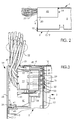
- Figure 1 the rectangular plan of the housing 1 of a tachograph serving as an exemplary embodiment.
- the Housing 1 is made of two components, preferably made of sheet metal put together, namely from a hood-like cover part 2 and one Bottom part 3 ( Figure 2).
- On the cover part 2 are essentially the rear wall 4, the side walls 5 and 6 and a cover plate 7 of the housing 1 educated.
- On the bottom part 3 edge strips 8, 9 and 10 are formed, the after joining base part 3 and cover part 2 the side walls 5, 6 and the rear wall 4 overlap sufficiently.
- the Joining takes place for example by means of the sidebars trained bar, which, because what is not essential to the invention, in individual is not shown, formed on the side walls 5, 6, after internal tongues are assigned.
- the front of the housing 1 is through a front wall 11 completed. With 12 and 13 are fastening claws referred to when installing the tachograph in the mounting frame provided recesses come into operative connection.
- a cover cap is referred to, which is flush with the outside on all sides closes the housing 1 and one in the case of the exemplary embodiment
- the cutout 20 provided in the corner of the cover part 2 closes, except for a designated in Figure 3 at 21 rear opening through which the Tachograph associated lines can be inserted or removed.
- the Cable bundle for example for the voltage supply of the device, the measurement and signal transmission as well as the control of other devices, especially the control of display instruments required Lines are designated by 22.
- the lines 22 are assigned four 8-pin plugs, by which one in the sectional view, Figure 3, is designated 23.
- the connector 23 is held by a connector base 24, which is on the one hand by means of spacers, two of which, 25 and 26, are shown in FIG. 3, is supported on a printed circuit board 27 of the tachograph and which on the other hand by means of integrally formed latching hooks, one is designated 28, the printed circuit board 27 engages behind.
- a support 29 also integrally formed on the plug base 24 serves by passing the circuit board 27 or through the circuit board 27 guided and directly assigned to the bottom part 3, the discharge of Printed circuit board 27 when plug 23 is set.
- FIG. 19 The perspective views of the cap 19, Figures 4 and 5, show that the rectangular cover plate 38 stiffened by ribs Wall elements 39, 40 and 41 are assigned and that on the transverse to the two parallel wall elements 39, 40 outwardly pointing locking lugs 42 and 43 are molded.
- hooks 47 and 48 are formed facing each other, namely such that they are, for example, only half the wall thickness of the Wall legs 44, 45 are formed, in other words with respect to the Front plane of the wall legs 44, 45 are formed recessed.
Landscapes
- Physics & Mathematics (AREA)
- General Physics & Mathematics (AREA)
- Time Recorders, Dirve Recorders, Access Control (AREA)
Abstract
Description
- Figur 1
- eine Draufsicht eines Fahrtschreibers mit der erfindungsgemäßen, die eingehenden und ausgehenden Leitungen niederhaltenden Abdeckkappe,
- Figur 2
- eine teilweise Seitenansicht des Fahrtschreibers gemäß Figur 1,
- Figur 3
- eine Schnittdarstellung gemäß der Schnittlinie A in Figur 1,
- Figur 4
- eine perspektivische Ansicht der Abdeckkappe von oben,
- Figur 5
- eine perspektivische Ansicht der Abdeckkappe von unten.
Claims (10)
- Fahrtschreiber mit einem flachen, quaderförmigen Gehäuse, in welchem eine Leiterplatte weitgehend formatfüllend befestigt ist und mit der Leiterplatte in Richtung der Hochachse des Gehäuses Kontaktzungen verbunden sind, wobei den Kontaktzungen ein auf der Leiterplatte befestigter, mit mehreren Steckerfassungen versehener Steckersockel zugeordnet ist und in dem Gehäuse eine den Zugang zum Steckersockel ermöglichende Freisparung ausgebildet ist und bei welchem Stecker mit geradem Abgang der mit den Kontaktbuchsen der Stecker verbundenen Leitungen Anwendung finden,
dadurch gekennzeichnet,dass die Freisparung (20) im Gehäuse (1) derart ausgebildet ist, dass sie wenigstens in die Rückwand (4) und in die Deckelplatte (7) des Gehäuses (1) mit rechteckförmigen Ausschnitten eingreift,dass eine mit dem Gehäuse (1) verbindbare Abdeckkappe (19) vorgesehen ist derart, dass nach dem Anbringen der Abdeckkappe (19) an dem Gehäuse (1) die Freisparung (20) deckelseitig abgedeckt und rückwandseitig weitgehend offen ist unddass an der Abdeckkappe (19) und an dem Gehäuse (1) einander zugeordnete Haltemittel (42, 43, 36 und 47, 48, 37) derart ausgebildet sind, dass die Abdeckkappe (19) in Entnahmerichtung der Stecker (23) unlösbar mit dem Gehäuse (1) verbindbar ist. - Fahrtschreiber nach Anspruch 1,
dadurch gekennzeichnet, dass innerhalb der Freisparung (20) in das Gehäuse (1) hineinragende Leisten (36 und 37) ausgebildet sind derart, dass eine erste Leiste (36) am deckelseitigen Ausschnitt der Freisparung (20) rückwandparallel und eine zweite Leiste (37) am rückwandseitigen Ausschnitt der Freisparung (20) deckelparallel angeordnet ist. - Fahrtschreiber nach Anspruch 1,
dadurch gekennzeichnet,dass die Abdeckkappe (19) aus einer im wesentlichen rechteckförmigen Deckplatte (38) mit wenigstens an drei Seiten ausgeformten Wandelementen (39, 40, 41) besteht,dass an dem quer zu zwei parallelen Wandelementen (39, 40) ausgebildeten Wandelement (41) nach außen weisende Rastnasen (42, 43) vorgesehen sind unddass in einer zu dem die Rastnasen (43, 43) tragenden Wandelement (41) parallelen Ebene an den sich gegenüberstehenden Wandelementen (39, 40) gegeneinander weisende Haken (47, 48) angeformt sind. - Fahrtschreiber nach Anspruch 3,
dadurch gekennzeichnet,dass an der einen Seite der Deckplatte (38) mit den sich gegenüberstehenden Wandelementen (39, 40, 41) in Verbindung stehende Wandschenkel (44, 45) ausgebildet sind unddass die Haken (47, 48) an den Wandschenkeln (44, 45) angeformt sind. - Fahrtschreiber nach Anspruch 3,
dadurch gekennzeichnet, dass wenigstens an der Innenseite der Deckplatte (38) Rippen ausgebildet sind. - Fahrtschreiber nach Anspruch 4,
dadurch gekennzeichnet, dass die Haken (47, 48) in bezug auf die Frontebene der Wandschenkel (44, 45) zurückversetzt angeformt sind. - Fahrtschreiber nach Anspruch 4,
dadurch gekennzeichnet, dass in der Ebene der Wandschenkel (44, 45) ein die Wandschenkel (44, 45) und die Deckplatte (38) verbindender Steg (46) ausgebildet ist. - Fahrtschreiber nach Anspruch 1,
dadurch gekennzeichnet,dass die Abdeckkappe (19) und die Freisparung (20) im Gehäuse (1) derart einander zugeordnet ausgebildet sind, dass die Abdeckkappe (19) wenigstens bündig ist mit der Deckelplatte (7) des Gehäuses (1) unddass zwischen der Abdeckkappe (19) und der Rückwand (4) des Gehäuses (1) eine einen losen Durchtritt der innerhalb der Abdeckkappe (19) umgelenkten Leitungen (22) ermöglichende Öffnung (21) gegeben ist. - Fahrtschreiber nach Anspruch 1,
dadurch gekennzeichnet, dass für das Gehäuse (1) ein Deckelteil bestehend aus einer Deckelplatte (7), zwei Seitenwänden (5, 6) und einer Rückwand (4) vorgesehen ist. - Fahrtschreiber nach Anspruch 1,
dadurch gekennzeichnet, dass die Haltemittel (42, 43, 36 und 47, 48, 37) derart ausgebildet sind, dass nach dem Zusammenfügen von Abdeckkappe (19) und Gehäuse (1), die durch die Abdeckkappe (19) niedergehaltenen Leitungen (22) eine Lagesicherung der Abdeckkappe (19) ausüben.
Applications Claiming Priority (2)
| Application Number | Priority Date | Filing Date | Title |
|---|---|---|---|
| DE20012208U DE20012208U1 (de) | 2000-07-14 | 2000-07-14 | Fahrtschreiber mit einem flachen, quaderförmigen Gehäuse |
| DE20012208U | 2000-07-14 |
Publications (2)
| Publication Number | Publication Date |
|---|---|
| EP1172769A2 true EP1172769A2 (de) | 2002-01-16 |
| EP1172769A3 EP1172769A3 (de) | 2005-01-19 |
Family
ID=7943929
Family Applications (1)
| Application Number | Title | Priority Date | Filing Date |
|---|---|---|---|
| EP01116504A Ceased EP1172769A3 (de) | 2000-07-14 | 2001-07-07 | Fahrtschreiber mit einem flachen, quaderförmigen Gehäuse |
Country Status (3)
| Country | Link |
|---|---|
| EP (1) | EP1172769A3 (de) |
| BR (1) | BR0102880A (de) |
| DE (1) | DE20012208U1 (de) |
Cited By (1)
| Publication number | Priority date | Publication date | Assignee | Title |
|---|---|---|---|---|
| EP1357776A1 (de) * | 2002-04-26 | 2003-10-29 | Siemens Aktiengesellschaft | Elektronisches Einbaugerät |
Families Citing this family (1)
| Publication number | Priority date | Publication date | Assignee | Title |
|---|---|---|---|---|
| AT513121B1 (de) * | 2013-11-05 | 2015-05-15 | Avl List Gmbh | Mobiles Messgerät |
Family Cites Families (3)
| Publication number | Priority date | Publication date | Assignee | Title |
|---|---|---|---|---|
| JP2572255B2 (ja) * | 1988-03-25 | 1997-01-16 | チノン株式会社 | 電気機器の筐体 |
| DE9315970U1 (de) * | 1993-10-20 | 1993-12-02 | Mannesmann Kienzle Gmbh, 78052 Villingen-Schwenningen | Anordnung zum Verschließen einer Öffnung in einem Gehäuse |
| DE29604323U1 (de) * | 1996-03-08 | 1996-04-25 | VDO Adolf Schindling AG, 60326 Frankfurt | Vorrichtung zum Transport und zur Kontaktierung von Datenkarten in Datenerfassungsgeräten insbesondere in Fahrtschreibern |
-
2000
- 2000-07-14 DE DE20012208U patent/DE20012208U1/de not_active Expired - Lifetime
-
2001
- 2001-07-07 EP EP01116504A patent/EP1172769A3/de not_active Ceased
- 2001-07-13 BR BR0102880-4A patent/BR0102880A/pt not_active IP Right Cessation
Cited By (2)
| Publication number | Priority date | Publication date | Assignee | Title |
|---|---|---|---|---|
| EP1357776A1 (de) * | 2002-04-26 | 2003-10-29 | Siemens Aktiengesellschaft | Elektronisches Einbaugerät |
| US7016197B2 (en) | 2002-04-26 | 2006-03-21 | Siemens Aktiengesellschaft | Electronic built-in device |
Also Published As
| Publication number | Publication date |
|---|---|
| DE20012208U1 (de) | 2000-10-26 |
| EP1172769A3 (de) | 2005-01-19 |
| BR0102880A (pt) | 2002-02-19 |
Similar Documents
| Publication | Publication Date | Title |
|---|---|---|
| DE69320016T2 (de) | Kartenrandverbinder | |
| DE4243656C2 (de) | Trägermaterial-Befestigungsvorrichtung | |
| DE602005000149T2 (de) | Anschlussanordnung eines elektrischen Gerätes | |
| DE3537400A1 (de) | Gehaeuse fuer eine erweiterbare periphere interface-einheit | |
| DE19706536C2 (de) | Montageanordnung für ein elektrisches Modul | |
| EP0667049B1 (de) | Einrichtung zum halten eines geschirmten kabelsteckers | |
| DE102009045550A1 (de) | Anschluss | |
| DE69006167T2 (de) | Verbesserte flächige Trägerstruktur für Leiterplatte. | |
| DE10218891B4 (de) | Elektronisches Einbaugerät | |
| DE69316548T2 (de) | Buchsenanordnung | |
| DE2511385C3 (de) | Elektrische Anschlußklemme | |
| EP1520330B1 (de) | Träger für modulgehäuse | |
| EP0514671B1 (de) | Prüfvorrichtung | |
| EP1172769A2 (de) | Fahrtschreiber mit einem flachen, quaderförmigen Gehäuse | |
| DE102004062879A1 (de) | Elektrisches Kontaktelement sowie Kontaktierungseinrichtung mit Kontaktelement | |
| DE2355509C2 (de) | Montageeinheit für Elektro-Installationszwecke | |
| DE60315928T2 (de) | Kombination einer Vorrichtung mit Haltevorrichtung zur Montage in einer Paneelöffnung | |
| DE102023122398A1 (de) | Gehäuse für einen RJ-Steckverbinder | |
| EP3942541B1 (de) | Trägerkomponente eines gehäuses einer gefahrenmelderzentrale und eine gefahrenmelderzentrale, vorzugsweise einer einbruch-, brandmelder- und/oder löschsteuerzentrale | |
| DE102011089591B4 (de) | Adapter zum Koppeln eines Leistungsschalters mit einem Zusatzmodul | |
| DE102011104029A1 (de) | Wechselschild für Reiheneinbaugeräte | |
| DE4342740A1 (de) | Metallgehäuse für eine kleine Fernmeldevermittlungsanlage | |
| EP0935314A2 (de) | Steckverbinder-Gehäuse im 19 Zoll-Gerätesystem | |
| EP1402480A2 (de) | Mittel zum verbinden einer frontblende eines quaderförmigen einbaugerätes mit dessen einbaugehäuseteil | |
| DE202020107089U1 (de) | Installationsdose |
Legal Events
| Date | Code | Title | Description |
|---|---|---|---|
| PUAI | Public reference made under article 153(3) epc to a published international application that has entered the european phase |
Free format text: ORIGINAL CODE: 0009012 |
|
| AK | Designated contracting states |
Kind code of ref document: A2 Designated state(s): AT BE CH CY DE DK ES FI FR GB GR IE IT LI LU MC NL PT SE TR |
|
| AX | Request for extension of the european patent |
Free format text: AL;LT;LV;MK;RO;SI |
|
| RAP1 | Party data changed (applicant data changed or rights of an application transferred) |
Owner name: SIEMENS AKTIENGESELLSCHAFT |
|
| PUAL | Search report despatched |
Free format text: ORIGINAL CODE: 0009013 |
|
| AK | Designated contracting states |
Kind code of ref document: A3 Designated state(s): AT BE CH CY DE DK ES FI FR GB GR IE IT LI LU MC NL PT SE TR |
|
| AX | Request for extension of the european patent |
Extension state: AL LT LV MK RO SI |
|
| 17P | Request for examination filed |
Effective date: 20041220 |
|
| AKX | Designation fees paid |
Designated state(s): DE FR GB SE |
|
| 17Q | First examination report despatched |
Effective date: 20070515 |
|
| RAP1 | Party data changed (applicant data changed or rights of an application transferred) |
Owner name: CONTINENTAL AUTOMOTIVE GMBH |
|
| STAA | Information on the status of an ep patent application or granted ep patent |
Free format text: STATUS: THE APPLICATION HAS BEEN REFUSED |
|
| 18R | Application refused |
Effective date: 20090915 |