EP1172345A1 - Dielectric ceramic for high frequency, dielectric resonator, dielectric filter, dielectric duplexer and communication unit - Google Patents
Dielectric ceramic for high frequency, dielectric resonator, dielectric filter, dielectric duplexer and communication unit Download PDFInfo
- Publication number
- EP1172345A1 EP1172345A1 EP01116854A EP01116854A EP1172345A1 EP 1172345 A1 EP1172345 A1 EP 1172345A1 EP 01116854 A EP01116854 A EP 01116854A EP 01116854 A EP01116854 A EP 01116854A EP 1172345 A1 EP1172345 A1 EP 1172345A1
- Authority
- EP
- European Patent Office
- Prior art keywords
- dielectric
- input
- ceramic
- duplexer
- filters
- Prior art date
- Legal status (The legal status is an assumption and is not a legal conclusion. Google has not performed a legal analysis and makes no representation as to the accuracy of the status listed.)
- Granted
Links
- 239000000919 ceramic Substances 0.000 title claims abstract description 52
- 238000004891 communication Methods 0.000 title claims description 12
- 239000000203 mixture Substances 0.000 claims abstract description 11
- 239000013078 crystal Substances 0.000 claims abstract description 10
- 230000005540 biological transmission Effects 0.000 claims description 12
- 229910052715 tantalum Inorganic materials 0.000 claims description 3
- 239000010955 niobium Substances 0.000 description 19
- 239000011701 zinc Substances 0.000 description 10
- VTYYLEPIZMXCLO-UHFFFAOYSA-L Calcium carbonate Chemical compound [Ca+2].[O-]C([O-])=O VTYYLEPIZMXCLO-UHFFFAOYSA-L 0.000 description 8
- 239000011575 calcium Substances 0.000 description 8
- 239000011777 magnesium Substances 0.000 description 8
- 230000008878 coupling Effects 0.000 description 5
- 238000010168 coupling process Methods 0.000 description 5
- 238000005859 coupling reaction Methods 0.000 description 5
- 239000000843 powder Substances 0.000 description 5
- 229910000019 calcium carbonate Inorganic materials 0.000 description 4
- VTHJTEIRLNZDEV-UHFFFAOYSA-L magnesium dihydroxide Chemical compound [OH-].[OH-].[Mg+2] VTHJTEIRLNZDEV-UHFFFAOYSA-L 0.000 description 4
- 239000000347 magnesium hydroxide Substances 0.000 description 4
- 229910001862 magnesium hydroxide Inorganic materials 0.000 description 4
- 239000000463 material Substances 0.000 description 4
- 229910052751 metal Inorganic materials 0.000 description 4
- 239000002184 metal Substances 0.000 description 4
- TWNQGVIAIRXVLR-UHFFFAOYSA-N oxo(oxoalumanyloxy)alumane Chemical compound O=[Al]O[Al]=O TWNQGVIAIRXVLR-UHFFFAOYSA-N 0.000 description 4
- 239000010936 titanium Substances 0.000 description 4
- 239000002994 raw material Substances 0.000 description 3
- VYPSYNLAJGMNEJ-UHFFFAOYSA-N Silicium dioxide Chemical compound O=[Si]=O VYPSYNLAJGMNEJ-UHFFFAOYSA-N 0.000 description 2
- GWEVSGVZZGPLCZ-UHFFFAOYSA-N Titan oxide Chemical compound O=[Ti]=O GWEVSGVZZGPLCZ-UHFFFAOYSA-N 0.000 description 2
- 239000000654 additive Substances 0.000 description 2
- 230000000996 additive effect Effects 0.000 description 2
- 229910052782 aluminium Inorganic materials 0.000 description 2
- AYJRCSIUFZENHW-UHFFFAOYSA-L barium carbonate Chemical compound [Ba+2].[O-]C([O-])=O AYJRCSIUFZENHW-UHFFFAOYSA-L 0.000 description 2
- WMWLMWRWZQELOS-UHFFFAOYSA-N bismuth(iii) oxide Chemical compound O=[Bi]O[Bi]=O WMWLMWRWZQELOS-UHFFFAOYSA-N 0.000 description 2
- 229910052791 calcium Inorganic materials 0.000 description 2
- 238000010586 diagram Methods 0.000 description 2
- GNTDGMZSJNCJKK-UHFFFAOYSA-N divanadium pentaoxide Chemical compound O=[V](=O)O[V](=O)=O GNTDGMZSJNCJKK-UHFFFAOYSA-N 0.000 description 2
- 229910052749 magnesium Inorganic materials 0.000 description 2
- 238000000034 method Methods 0.000 description 2
- 229910052758 niobium Inorganic materials 0.000 description 2
- URLJKFSTXLNXLG-UHFFFAOYSA-N niobium(5+);oxygen(2-) Chemical compound [O-2].[O-2].[O-2].[O-2].[O-2].[Nb+5].[Nb+5] URLJKFSTXLNXLG-UHFFFAOYSA-N 0.000 description 2
- 239000007858 starting material Substances 0.000 description 2
- 229910052718 tin Inorganic materials 0.000 description 2
- 229910052719 titanium Inorganic materials 0.000 description 2
- 238000001238 wet grinding Methods 0.000 description 2
- 229910052725 zinc Inorganic materials 0.000 description 2
- 229910011255 B2O3 Inorganic materials 0.000 description 1
- QPLDLSVMHZLSFG-UHFFFAOYSA-N CuO Inorganic materials [Cu]=O QPLDLSVMHZLSFG-UHFFFAOYSA-N 0.000 description 1
- XLOMVQKBTHCTTD-UHFFFAOYSA-N Zinc monoxide Chemical compound [Zn]=O XLOMVQKBTHCTTD-UHFFFAOYSA-N 0.000 description 1
- 239000011230 binding agent Substances 0.000 description 1
- 229910052681 coesite Inorganic materials 0.000 description 1
- 229910052906 cristobalite Inorganic materials 0.000 description 1
- 230000000593 degrading effect Effects 0.000 description 1
- 239000003989 dielectric material Substances 0.000 description 1
- 238000005516 engineering process Methods 0.000 description 1
- 238000002474 experimental method Methods 0.000 description 1
- XMFOQHDPRMAJNU-UHFFFAOYSA-N lead(II,IV) oxide Inorganic materials O1[Pb]O[Pb]11O[Pb]O1 XMFOQHDPRMAJNU-UHFFFAOYSA-N 0.000 description 1
- XGZVUEUWXADBQD-UHFFFAOYSA-L lithium carbonate Chemical compound [Li+].[Li+].[O-]C([O-])=O XGZVUEUWXADBQD-UHFFFAOYSA-L 0.000 description 1
- 229910052808 lithium carbonate Inorganic materials 0.000 description 1
- 239000011656 manganese carbonate Substances 0.000 description 1
- 229910000016 manganese(II) carbonate Inorganic materials 0.000 description 1
- 238000004519 manufacturing process Methods 0.000 description 1
- 238000005259 measurement Methods 0.000 description 1
- 238000000465 moulding Methods 0.000 description 1
- GNRSAWUEBMWBQH-UHFFFAOYSA-N nickel(II) oxide Inorganic materials [Ni]=O GNRSAWUEBMWBQH-UHFFFAOYSA-N 0.000 description 1
- BPUBBGLMJRNUCC-UHFFFAOYSA-N oxygen(2-);tantalum(5+) Chemical compound [O-2].[O-2].[O-2].[O-2].[O-2].[Ta+5].[Ta+5] BPUBBGLMJRNUCC-UHFFFAOYSA-N 0.000 description 1
- -1 rare earth compounds Chemical class 0.000 description 1
- 229910052761 rare earth metal Inorganic materials 0.000 description 1
- 239000000377 silicon dioxide Substances 0.000 description 1
- 229910052682 stishovite Inorganic materials 0.000 description 1
- 229910052905 tridymite Inorganic materials 0.000 description 1
- ZNOKGRXACCSDPY-UHFFFAOYSA-N tungsten(VI) oxide Inorganic materials O=[W](=O)=O ZNOKGRXACCSDPY-UHFFFAOYSA-N 0.000 description 1
Images

Classifications
-
- H—ELECTRICITY
- H01—ELECTRIC ELEMENTS
- H01P—WAVEGUIDES; RESONATORS, LINES, OR OTHER DEVICES OF THE WAVEGUIDE TYPE
- H01P7/00—Resonators of the waveguide type
- H01P7/10—Dielectric resonators
-
- C—CHEMISTRY; METALLURGY
- C04—CEMENTS; CONCRETE; ARTIFICIAL STONE; CERAMICS; REFRACTORIES
- C04B—LIME, MAGNESIA; SLAG; CEMENTS; COMPOSITIONS THEREOF, e.g. MORTARS, CONCRETE OR LIKE BUILDING MATERIALS; ARTIFICIAL STONE; CERAMICS; REFRACTORIES; TREATMENT OF NATURAL STONE
- C04B35/00—Shaped ceramic products characterised by their composition; Ceramics compositions; Processing powders of inorganic compounds preparatory to the manufacturing of ceramic products
- C04B35/01—Shaped ceramic products characterised by their composition; Ceramics compositions; Processing powders of inorganic compounds preparatory to the manufacturing of ceramic products based on oxide ceramics
- C04B35/46—Shaped ceramic products characterised by their composition; Ceramics compositions; Processing powders of inorganic compounds preparatory to the manufacturing of ceramic products based on oxide ceramics based on titanium oxides or titanates
- C04B35/462—Shaped ceramic products characterised by their composition; Ceramics compositions; Processing powders of inorganic compounds preparatory to the manufacturing of ceramic products based on oxide ceramics based on titanium oxides or titanates based on titanates
- C04B35/465—Shaped ceramic products characterised by their composition; Ceramics compositions; Processing powders of inorganic compounds preparatory to the manufacturing of ceramic products based on oxide ceramics based on titanium oxides or titanates based on titanates based on alkaline earth metal titanates
Definitions
- the present invention relates to a dielectric ceramic utilizable for a high frequency region such as the microwave region and the millimeter wave region, as well as a dielectric resonator, a dielectric filter, a dielectric duplexer and a communication unit using the ceramic.
- Dielectric ceramics are widely used as materials for a dielectric resonator, a dielectric filter and a circuit board mounted on an electronic devices which are utilized in high frequency regions such as the microwave region and the millimeter wave region for various applications including portable telephones, personal wireless sets and satellite broadcast receivers, for example.
- dielectric characteristics required for such a dielectric ceramic for high frequency enumerated are: (1) a large specific dielectric coefficient ( ⁇ r ) for meeting the requirement of miniaturization since the wavelength of an electromagnetic wave is shortened by 1/( ⁇ r ) 1/2 in a dielectric; (2) a small dielectric loss, that is, a large Q value; (3) excellent temperature stability of resonant frequency, that is, the temperature coefficient ( ⁇ f ) of resonant frequency being in the vicinity of 0 (ppm/°C), etc.
- dielectric ceramics represented by such as a Ba(Zn,Ta)O 3 -type composition, (Japanese Examined Patent Application Publication No. 58-25068), a Ba(Sn,Mg,Ta)O 3 -type composition (Japanese Examined Patent Application Publication No. 3-34164), a (Zr,Sn)TiO 4 -type composition (Japanese Examined Patent Application Publication No. 4-59267), and a Ba 2 Ti 9 O 20 composition (Japanese Unexamined Patent Application Publication No. 61-10806), are known.
- the Ba(Zn,Ta)O 3 -type and Ba(Sn,Mg,Ta)O 3 -type materials have very large Q values (at 1 GHz) ranging from 150,000 to 300,000, the specific dielectric constants ( ⁇ r ) are relatively small, ranging from 24 to 30.
- the (Zr,Sn)TiO 4 -type and Ba 2 Ti 9 O 20 -type materials have relatively large specific dielectric constants ( ⁇ r ) of from 37 to 40, and large Q values (at 1 GHz) of from 50,000 to 60,000.
- ⁇ r specific dielectric constant
- one of the objects of the present invention is to provide a dielectric ceramic for high frequency which has a large specific dielectric constant ( ⁇ r ) of from 40 to 60, a large Q value (at 1 GHz) of about 25,000 or more, and a temperature coefficient ( ⁇ f ) of resonant frequency which can be controlled within the range of about 0 ⁇ 30 (ppm/°C).
- Another object is to provide a dielectric resonator, a dielectric filter, a dielectric duplexer and a communication unit using the ceramic.
- the symbols a and b are preferably within the following ranges: 1.000 ⁇ a ⁇ 1.050; and 0.980 ⁇ b ⁇ 1.000.
- a dielectric resonator according to the present invention is characterized by having a dielectric ceramic actuated by electromagnetic coupling with the input/output terminals, wherein the dielectric ceramic is composed of the above-described dielectric ceramic for high frequency.
- a dielectric filter according to the present invention is characterized in that it comprises an outer coupling as well as the above-described dielectric resonator.
- a dielectric duplexer is characterized by comprising at least two dielectric filters, input/output connection connected to each of the dielectric filters, and an antenna connection connected commonly to the dielectric filters, wherein at least one of the above-described dielectric filters is the dielectric filter described above in the previous paragraph.
- a communication unit is characterized by comprising the above-described dielectric duplexer, a transmission circuit connected to at least one of the input/output connections of the dielectric duplexer, a receiving circuit connected to at least one of the input/output connection which is different from the above-described input/output connection connected to the transmission circuit, and an antenna connected to the antenna connection of the dielectric duplexer.
- Fig. 1 is a cross-sectional view illustrating the fundamental structure of a dielectric resonator 1 according to an embodiment of the present invention.
- the dielectric resonator 1 has a metal case 2.
- a pillar-shaped dielectric ceramic 4 is supported by a support 3.
- an input terminal 5 and an output terminal 6 are held by the metal case 2 and are isolated from the metal case 2.
- the dielectric ceramic 4 is actuated by electromagnetic coupling with the input terminal 5 and the output terminal 6, through which only the signals at a specific frequency among those inputted from the input terminal 5 are outputted at the output terminal 6.
- the dielectric ceramic 4 in the dielectric resonator 1 is composed of a dielectric ceramic for high frequency according to the present invention.
- the dielectric resonator in Fig. 1 is a TE01 ⁇ mode dielectric resonator. It is noted, however, that the dielectric ceramic for high frequency according to the present invention can also be used for other dielectric resonators of various types such as TE mode, TM mode and TEM mode.
- Fig. 2 is a block diagram showing an example of a communication unit according to the present invention.
- This communication unit 10 comprises a dielectric duplexer 12, a transmission circuit 14, a receiving circuit 16 and an antenna 18.
- the transmission circuit 14 is connected to an input connector 20 of the dielectric duplexer 12, and the receiving circuit 16 is connected to an output connector 22 of the dielectric duplexer 12.
- the antenna 18 is connected to an antenna connector 24 of the dielectric duplexer 12.
- This dielectric duplexer 12 comprises two dielectric filters 26 and 28.
- the dielectric filters 26 and 28 are formed by connecting the dielectric resonators according to the present invention to outer coupling. In this example, they are formed by connecting the input/output terminals of the dielectric resonators 1 with the outer coupling 30, respectively. Accordingly, the dielectric filter 26 is located between the input connector 20 and the other dielectric filter 28 to connect them, and the other dielectric filter 28 is located between the dielectric filter 26 and the output connector 22 to connect them.
- ⁇ ⁇ 0.340. This is because the Q value is less than 25,000 or the temperature coefficient ( ⁇ f ) of resonant frequency is shifted toward the more minus side of -30 ppm/°C when ⁇ > 0.340.
- 0.980 ⁇ a ⁇ 1.050 This is because the Q value is less than 25,000 when a ⁇ 0.980 or a > 1.050. It is preferable that the formula is: 1.000 ⁇ a ⁇ 1.050 since a higher Q value is obtained.
- 0.980 ⁇ b ⁇ 1.050 This is because the Q value is less than 25,000 when b ⁇ 0.980 or b > 1.050. It is preferable that the formula is: 0.980 ⁇ b ⁇ 1.000 since a higher Q value is obtained.
- high-purity calcium carbonate (CaCO 3 ), titanium oxide (TiO 2 ), magnesium hydroxide (Mg(OH) 2 ), zinc oxide (ZnO), niobium oxide (Nb 2 O 5 ) and aluminum oxide (Al 2 O 3 ) were prepared.
- Samples 48 to 59 shown in Table 2 are those obtained by changing the values of a, b and c for the composition of Sample 29 in Table 1.
- these raw material powders which had been prepared were subjected to wet grinding for 16 hours with a ball mill. After that, they were dehydrated, dried and then calcined at from 1,100 to 1,300 °C for three hours. Appropriate amounts of binders were added to the calcined powders and the mixtures were subjected again to wet grinding with a ball mill for 16 hours to form sample powders for experiments.
- the sample powders thus obtained were subjected to press molding at a pressure of from 1,000 to 2,000 kg/cm 2 to form disks. Then, they were baked at a temperature of from 1,400 to 1,600 °C in the atmosphere for 4 to 24 hours to obtain ceramics with a diameter of 10 mm and a thickness of 5 mm, comprising a perovskite crystal phase as the main crystal phase.
- y is specified as: 0.380 ⁇ y ⁇ 0.570. This is because the temperature coefficient ( ⁇ f ) of resonant frequency is shifted greatly toward the more minus side of -30 ppm/°C when y ⁇ 0.380, as shown in Samples 13, 17, 22, 26, 27 and 34. This is also because the temperature coefficient ( ⁇ f ) of resonant frequency is larger than +30 ppm/°C when y > 0.570, as shown in Samples 8, 12, 16, 25, 30, 38 and 42.
- ⁇ is specified as: ⁇ ⁇ 0.340. This is because the temperature coefficient ( ⁇ f ) of resonant frequency is shifted toward the more minus side of -30 ppm/°C when ⁇ > 0.340, as shown in Sample 39.
- the symbol a is specified as: 0.980 ⁇ a ⁇ 1.050. This is because the Q value is less than 25,000 when a ⁇ 0.980, as shown in Sample 48. This is also because the Q value is less than 25,000 when a > 1.050, as shown in Sample 51. Furthermore, it is preferable to specify the symbol a as: 1.000 ⁇ a ⁇ 1.050 since a Q value more than 28,000 can be obtained as shown in Sample 50.
- the symbol b is specified as: 0.980 ⁇ b ⁇ 1.050. This is because the Q value is less than 25,000 when b ⁇ 0.980, as shown in Sample 52. This is also because the Q value is less than 25,000 when b > 1.050, as shown in Sample 55. It is preferable to specify the symbol a as: 0.980 ⁇ a ⁇ 1.000 since a Q value more than 28,000 can be obtained as shown in Sample 53.
- c is specified as: 0.980 ⁇ c ⁇ 1.050. This is because the Q value is less than 25,000 when c ⁇ 0.980, as shown in Sample 56. This is also because the Q value is less than 25,000 when c > 1.050, as shown in Sample 59.
- high-purity calcium carbonate (CaCO 3 ), titanium oxide (TiO 2 ), magnesium hydroxide (Mg(OH) 2 ), niobium oxide (Nb 2 O 5 ), aluminum oxide (Al 2 O 3 ) and tantalum oxide (Ta 2 O 5 ) were prepared.
- the baking temperature can be lowered by 20 to 30°C without degrading the properties by adding from about 0.01% to 1.0% by weight of an additive such as SiO 2 , MnCO 3 , B 2 O 3 , NiO, CuO, Li 2 CO 3 , Pb 3 O 4 , Bi 2 O 3 , V 2 O 5 or WO 3 .
- an additive such as SiO 2 , MnCO 3 , B 2 O 3 , NiO, CuO, Li 2 CO 3 , Pb 3 O 4 , Bi 2 O 3 , V 2 O 5 or WO 3 .
- addition of from about 1% to 3% by weight of BaCO 3 , various rare earth compounds, etc. makes it possible to finely control the specific dielectric constant ( ⁇ r ) and the temperature properties, providing excellent dielectric ceramics.
- a dielectric ceramic for high frequency can be obtained according to the present invention, which has a large specific dielectric constant ( ⁇ r ) of from 40 to 60, a large Q value (at 1 GHz) of 25,000 or more and a temperature coefficient ( ⁇ f ) of resonant frequency which can be controlled within the range of 0 ⁇ 30 (ppm/°C).
- a dielectric ceramic having such a composition is used for manufacturing a dielectric resonator, a dielectric filter, a dielectric duplexer or a communication unit, good properties can be realized for each of them.
Landscapes
- Engineering & Computer Science (AREA)
- Chemical & Material Sciences (AREA)
- Ceramic Engineering (AREA)
- Manufacturing & Machinery (AREA)
- Materials Engineering (AREA)
- Structural Engineering (AREA)
- Organic Chemistry (AREA)
- Inorganic Insulating Materials (AREA)
- Control Of Motors That Do Not Use Commutators (AREA)
- Compositions Of Oxide Ceramics (AREA)
- Ceramic Capacitors (AREA)
Abstract
Description
- The present invention relates to a dielectric ceramic utilizable for a high frequency region such as the microwave region and the millimeter wave region, as well as a dielectric resonator, a dielectric filter, a dielectric duplexer and a communication unit using the ceramic.
- Dielectric ceramics are widely used as materials for a dielectric resonator, a dielectric filter and a circuit board mounted on an electronic devices which are utilized in high frequency regions such as the microwave region and the millimeter wave region for various applications including portable telephones, personal wireless sets and satellite broadcast receivers, for example.
- As the dielectric characteristics required for such a dielectric ceramic for high frequency, enumerated are: (1) a large specific dielectric coefficient (εr) for meeting the requirement of miniaturization since the wavelength of an electromagnetic wave is shortened by 1/(εr)1/2 in a dielectric; (2) a small dielectric loss, that is, a large Q value; (3) excellent temperature stability of resonant frequency, that is, the temperature coefficient (τf) of resonant frequency being in the vicinity of 0 (ppm/°C), etc.
- Conventionally, dielectric ceramics represented by such as a Ba(Zn,Ta)O3-type composition, (Japanese Examined Patent Application Publication No. 58-25068), a Ba(Sn,Mg,Ta)O3-type composition (Japanese Examined Patent Application Publication No. 3-34164), a (Zr,Sn)TiO4-type composition (Japanese Examined Patent Application Publication No. 4-59267), and a Ba2Ti9O20 composition (Japanese Unexamined Patent Application Publication No. 61-10806), are known.
- However, while the Ba(Zn,Ta)O3-type and Ba(Sn,Mg,Ta)O3-type materials have very large Q values (at 1 GHz) ranging from 150,000 to 300,000, the specific dielectric constants (εr) are relatively small, ranging from 24 to 30.
- On the other hand, the (Zr,Sn)TiO4-type and Ba2Ti9O20-type materials have relatively large specific dielectric constants (εr) of from 37 to 40, and large Q values (at 1 GHz) of from 50,000 to 60,000. However, it is difficult to realize a larger specific dielectric constant (εr), for example, to realize a value over 40.
- In recent years, the requirements of reduction in loss and miniaturization for electronic devices have been increased. Accordingly, requirements for developing dielectric materials which have further excellent dielectric characteristics, especially both a large specific dielectric constant (εr) and a large Q value, have been increased. However, the present technologies cannot meet these requirements fully.
- Hereupon, one of the objects of the present invention is to provide a dielectric ceramic for high frequency which has a large specific dielectric constant (εr) of from 40 to 60, a large Q value (at 1 GHz) of about 25,000 or more, and a temperature coefficient (τf) of resonant frequency which can be controlled within the range of about 0±30 (ppm/°C). Another object is to provide a dielectric resonator, a dielectric filter, a dielectric duplexer and a communication unit using the ceramic.
- To achieve the above-described objects, a dielectric ceramic for high frequency according to the present invention is characterized by comprising Ca, Ti, Mg, Zn, Nb and Al, by having a constitution represented by the formula: yCaTiaO1+2a-(1-y)xCa{(MgzZn1-z)1/3Nb2/3}bO1+2b-(1-y)(1-x)Ca(Al1/2Nb1/2)cO1+2c (where x and y are each a molar ratio), wherein α, x, y, z, a, b and c are in the ranges of the following formulae α=(1-y)x: α ≤ 0.340; 0 < x ≤ 0.600; 0.380 ≤ y ≤ 0.570; 0 ≤ z ≤ 1.000; 0.980 ≤ a ≤ 1.050; 0.980 ≤ b ≤ 1.050; and 0.980 ≤ c ≤ 1.050, and by comprising a perovskite crystal phase as a main crystal.
- Another dielectric ceramic for high frequency according to the present invention is characterized in that it is obtained by further including Ta in the above-described dielectric ceramic for high frequency, and it has a constitution represented by the formula: yCaTiaO1+2a-(1-y)xCa{(MgzZn1-z)1/3(NbdTa1-d)2/3}bO1+2b-(1-y)(1-x)Ca{Al1/2(NbdTa1-d)1/2}cO1+2c (where x and y are each a molar ratio), wherein α, x, y, z, a, b, c and d are in the ranges of the following formulae α = (1-y)x: α ≤ 0.340; 0 < x ≤ 0.600; 0.380 ≤ y ≤ 0.570; 0 ≤ z ≤ 1.000; 0.980 ≤ a ≤ 1.050; 0.980 ≤ b ≤ 1.050; 0.980 ≤ c ≤ 1.050; and 0 < d < 1.000.
- In each above-described dielectric ceramic for high frequency, the symbols a and b are preferably within the following ranges: 1.000 ≤ a ≤ 1.050; and 0.980 ≤ b ≤ 1.000.
- Furthermore, a dielectric resonator according to the present invention is characterized by having a dielectric ceramic actuated by electromagnetic coupling with the input/output terminals, wherein the dielectric ceramic is composed of the above-described dielectric ceramic for high frequency.
- Furthermore, a dielectric filter according to the present invention is characterized in that it comprises an outer coupling as well as the above-described dielectric resonator.
- Furthermore, a dielectric duplexer according to the present invention is characterized by comprising at least two dielectric filters, input/output connection connected to each of the dielectric filters, and an antenna connection connected commonly to the dielectric filters, wherein at least one of the above-described dielectric filters is the dielectric filter described above in the previous paragraph.
- Furthermore, a communication unit according to the present invention is characterized by comprising the above-described dielectric duplexer, a transmission circuit connected to at least one of the input/output connections of the dielectric duplexer, a receiving circuit connected to at least one of the input/output connection which is different from the above-described input/output connection connected to the transmission circuit, and an antenna connected to the antenna connection of the dielectric duplexer.
-
- Fig. 1 is a cross-sectional view illustrating a dielectric resonator according to an embodiment of the present invention; and
- Fig. 2 is a block diagram showing one example of a communication unit according to the present invention.
-
- Although the present invention is described with reference to the following figures and examples, it is to be understood that the invention is not limited to the precise embodiments described below.
- Fig. 1 is a cross-sectional view illustrating the fundamental structure of a
dielectric resonator 1 according to an embodiment of the present invention. - Referring to Fig. 1, the
dielectric resonator 1 has ametal case 2. In the inner space of themetal case 2, a pillar-shaped dielectric ceramic 4 is supported by a support 3. In addition, an input terminal 5 and anoutput terminal 6 are held by themetal case 2 and are isolated from themetal case 2. Thedielectric ceramic 4 is actuated by electromagnetic coupling with the input terminal 5 and theoutput terminal 6, through which only the signals at a specific frequency among those inputted from the input terminal 5 are outputted at theoutput terminal 6. The dielectric ceramic 4 in thedielectric resonator 1 is composed of a dielectric ceramic for high frequency according to the present invention. - The dielectric resonator in Fig. 1 is a TE01δ mode dielectric resonator. It is noted, however, that the dielectric ceramic for high frequency according to the present invention can also be used for other dielectric resonators of various types such as TE mode, TM mode and TEM mode.
- Fig. 2 is a block diagram showing an example of a communication unit according to the present invention. This
communication unit 10 comprises adielectric duplexer 12, atransmission circuit 14, areceiving circuit 16 and anantenna 18. Thetransmission circuit 14 is connected to aninput connector 20 of thedielectric duplexer 12, and thereceiving circuit 16 is connected to an output connector 22 of thedielectric duplexer 12. Theantenna 18 is connected to anantenna connector 24 of thedielectric duplexer 12. Thisdielectric duplexer 12 comprises twodielectric filters dielectric filters dielectric resonators 1 with theouter coupling 30, respectively. Accordingly, thedielectric filter 26 is located between theinput connector 20 and the otherdielectric filter 28 to connect them, and the otherdielectric filter 28 is located between thedielectric filter 26 and the output connector 22 to connect them. - The dielectric ceramic for high frequency according to the present invention comprises Ca, Ti, Mg, Zn, Nb and Al as described above, and has a constitution represented by the formula:
- First, 0 < x ≤ 0.600. This is because the Q value is less than 25,000 when either x = 0 or x > 0.600.
- As to 0.380 ≤ y ≤ 0.570. This is because the temperature coefficient (τf) of resonant frequency is out of the range of about 0 ± 30 ppm/°C when either y < 0.380 or y > 0.570.
- As to α, α ≤ 0.340. This is because the Q value is less than 25,000 or the temperature coefficient (τf) of resonant frequency is shifted toward the more minus side of -30 ppm/°C when α > 0.340.
- As to a, 0.980 ≤ a ≤ 1.050. This is because the Q value is less than 25,000 when a < 0.980 or a > 1.050. It is preferable that the formula is: 1.000 ≤ a ≤ 1.050 since a higher Q value is obtained.
- As to b, 0.980 ≤ b ≤ 1.050. This is because the Q value is less than 25,000 when b < 0.980 or b > 1.050. It is preferable that the formula is: 0.980 ≤ b ≤ 1.000 since a higher Q value is obtained.
- Regarding c, 0.980 ≤ c ≤ 1.050. This is because the Q value is less than 25,000 when c < 0.980 or c > 1.050.
- It is noted that excellent properties such as a specific dielectric constant (εr) of 40 or more, a Q value of 25,000 or more and a temperature coefficient (τf) of resonant frequency within the range of about 0 ± 30 ppm/°C, can be provided by replacing part of Nb of the above-described formula with Ta.
- Next, the present invention will be explained, based on the more concrete examples.
- As the starting materials, high-purity calcium carbonate (CaCO3), titanium oxide (TiO2), magnesium hydroxide (Mg(OH)2), zinc oxide (ZnO), niobium oxide (Nb2O5) and aluminum oxide (Al2O3) were prepared.
- Next, these materials were compounded to form ceramics having constitutions represented by the formula: yCaTiaO1+2a-(1-y)xCa{(MgzZn1-z)1/3Nb2/3}bO1+2b-(1-y)(1-x)Ca(Al1/2Nb1/2)cO1+2c (where x and y are each a molar ratio), as shown on top of Tables 1 and 2.
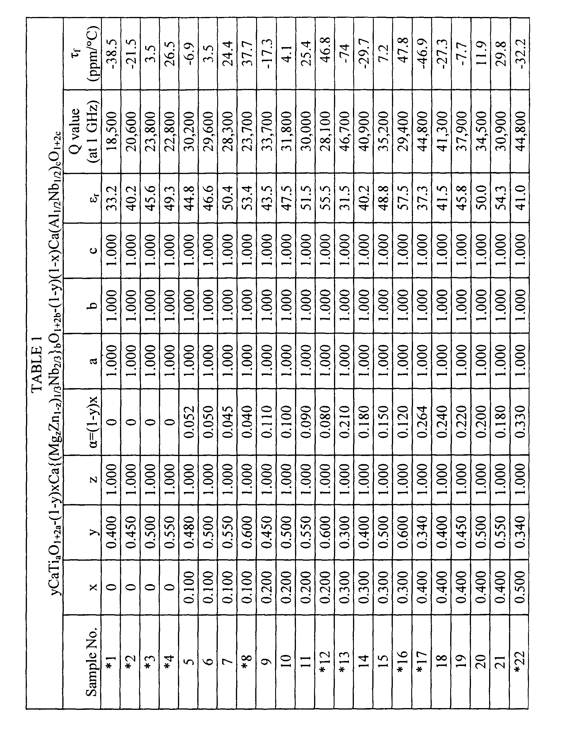
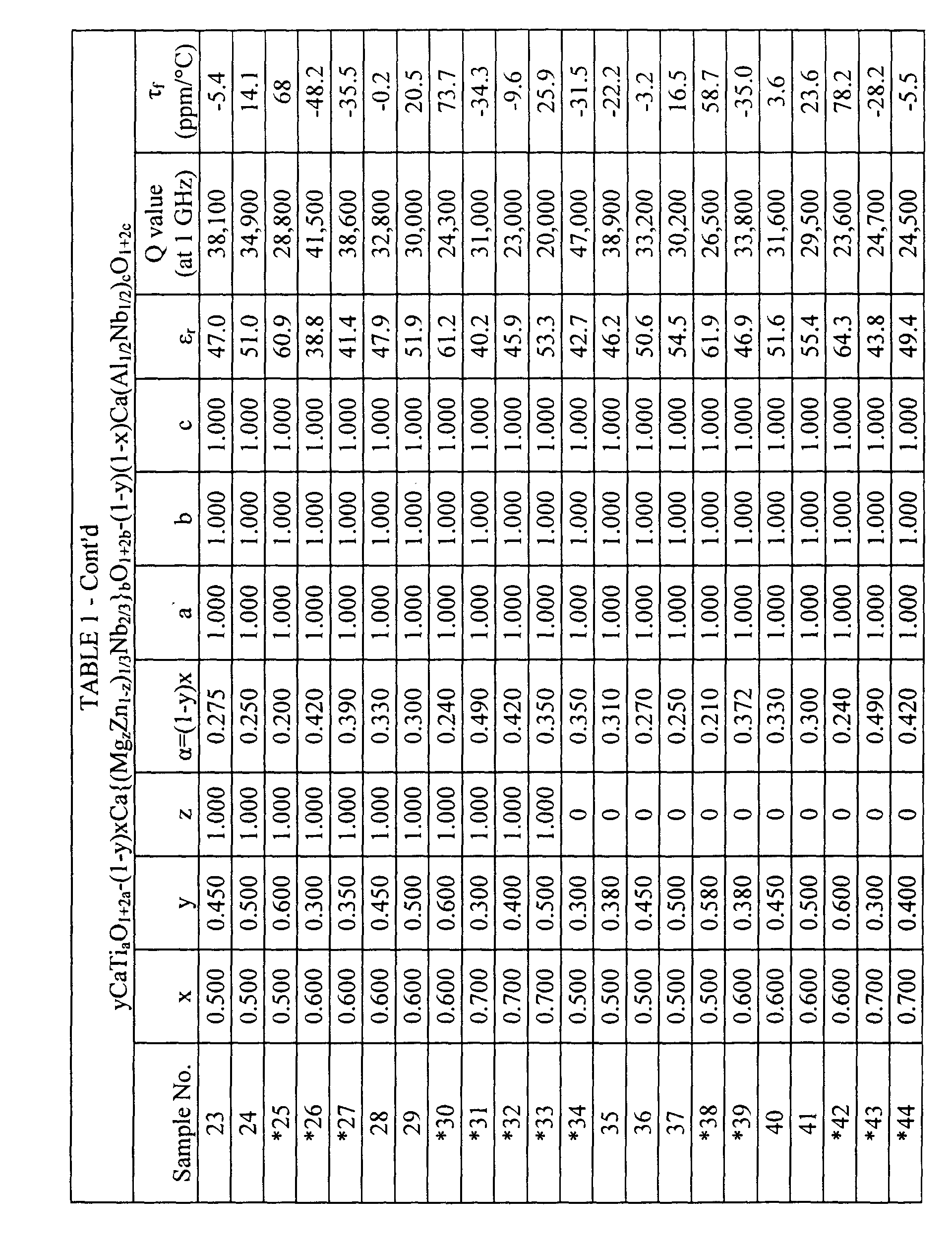

- It is noted that Samples 48 to 59 shown in Table 2 are those obtained by changing the values of a, b and c for the composition of Sample 29 in Table 1.
- Next, these raw material powders which had been prepared were subjected to wet grinding for 16 hours with a ball mill. After that, they were dehydrated, dried and then calcined at from 1,100 to 1,300 °C for three hours. Appropriate amounts of binders were added to the calcined powders and the mixtures were subjected again to wet grinding with a ball mill for 16 hours to form sample powders for experiments.
- Next, the sample powders thus obtained were subjected to press molding at a pressure of from 1,000 to 2,000 kg/cm2 to form disks. Then, they were baked at a temperature of from 1,400 to 1,600 °C in the atmosphere for 4 to 24 hours to obtain ceramics with a diameter of 10 mm and a thickness of 5 mm, comprising a perovskite crystal phase as the main crystal phase.
- The specific dielectric constants (εr) and the Q values in a frequency range for measurement of from 6 to 8 GHz were measured according to the dual-end short-circuited type dielectric resonator method, and the Q values converted to those at 1 GHz according to the rule: Q x f = constant. Also, the temperature coefficients (τf) of resonant frequency in the range of from 25 to 50°C were measured from the TE01δ mode resonator frequencies. The results are shown in Tables 1 and 2. In the Tables 1 and 2, those of sample numbers with an asterisk are out of the scope of the present invention.
- From Tables 1 and 2, it is evident that the samples within the range of the present invention can provide large Q values while maintaining large specific dielectric constant values (εr) in the microwave region.
- Referring to Tables 1 and 2, the reasons for specifying the symbols for the formula: yCaTiaO1+2a-(1-y)xCa{(MgzZn1-z)1/3Nb2/3}bO1+2b-(1-y)(1-x)Ca(Al1/2Nb1/2)cO1+2c according to the present invention, will be explained as follows.
- First, the symbol x is specified as: 0 < x ≤ 0.600. This is because the Q value is less than 25,000 when x = 0, as shown in
Samples - The symbol y is specified as: 0.380 ≤ y ≤ 0.570. This is because the temperature coefficient (τf) of resonant frequency is shifted greatly toward the more minus side of -30 ppm/°C when y < 0.380, as shown in
Samples 13, 17, 22, 26, 27 and 34. This is also because the temperature coefficient (τf) of resonant frequency is larger than +30 ppm/°C when y > 0.570, as shown inSamples - The symbol α is specified as: α ≤ 0.340. This is because the temperature coefficient (τf) of resonant frequency is shifted toward the more minus side of -30 ppm/°C when α > 0.340, as shown in Sample 39.
- The symbol a is specified as: 0.980 ≤ a ≤ 1.050. This is because the Q value is less than 25,000 when a < 0.980, as shown in Sample 48. This is also because the Q value is less than 25,000 when a > 1.050, as shown in Sample 51. Furthermore, it is preferable to specify the symbol a as: 1.000 ≤ a ≤ 1.050 since a Q value more than 28,000 can be obtained as shown in Sample 50.
- The symbol b is specified as: 0.980 ≤ b ≤ 1.050. This is because the Q value is less than 25,000 when b < 0.980, as shown in Sample 52. This is also because the Q value is less than 25,000 when b > 1.050, as shown in Sample 55. It is preferable to specify the symbol a as: 0.980 ≤ a ≤ 1.000 since a Q value more than 28,000 can be obtained as shown in Sample 53.
- The symbol c is specified as: 0.980 ≤ c ≤ 1.050. This is because the Q value is less than 25,000 when c < 0.980, as shown in Sample 56. This is also because the Q value is less than 25,000 when c > 1.050, as shown in Sample 59.
- As the starting materials, high-purity calcium carbonate (CaCO3), titanium oxide (TiO2), magnesium hydroxide (Mg(OH)2), niobium oxide (Nb2O5), aluminum oxide (Al2O3) and tantalum oxide (Ta2O5) were prepared.
- Next, these raw materials were compounded to form ceramic having compositions represented by the formula: yCaTiaO1+2a-(1-y)xCa{(MgzZn1-z)1/3(NbdTa1-d)2/3}bO1+2b-(1-y)(1-x)Ca{Al1/2(NbdTa1-d)1/2}cO1+2c as is shown on top of Table 3. These ceramics are obtained by replacing part of the Nb with Ta in the ceramics shown in Example 1 which are also within the range of the present invention.
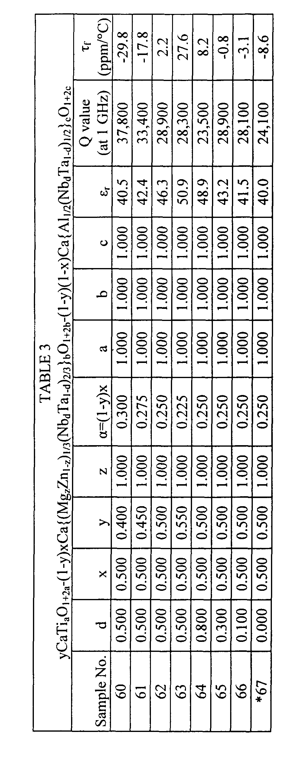
- Next, ceramics comprising a perovskite crystal phase as a main crystal were prepared from the raw material powders thus obtained according to the same process as that of Example 1. Then the specific dielectric constants (εr), the Q values and the temperature coefficients (τf) of resonant frequency were measured in the same way as in Example 1. The results are shown in Table 3.
- As is evident from Samples 60 to 66 in Table 3, by replacing part of the Nb with Ta, excellent properties were realized including a specific dielectric constants (εr) of 40 or more, Q values of 25,000 or more and temperature coefficients (τf) of resonant frequency within the range of 0 ± 30 ppm/°C, although the specific dielectric constants (εr) and the Q values were somewhat smaller than those of the samples without replacement of the Nb with Ta. However, if all of the Nb is replaced with Ta, the Q value will be less than 25,000 as shown in Sample 67.
- It is noted that a minute amount of an additive can be added to the dielectric ceramic for high frequency according to the present invention, as long as it does not damage the objects of the present invention. For example, the baking temperature can be lowered by 20 to 30°C without degrading the properties by adding from about 0.01% to 1.0% by weight of an additive such as SiO2, MnCO3, B2O3, NiO, CuO, Li2CO3, Pb3O4, Bi2O3, V2O5 or WO3. Furthermore, addition of from about 1% to 3% by weight of BaCO3, various rare earth compounds, etc. makes it possible to finely control the specific dielectric constant (εr) and the temperature properties, providing excellent dielectric ceramics.
- From the explanation as described above, it is evident that a dielectric ceramic for high frequency can be obtained according to the present invention, which has a large specific dielectric constant (εr) of from 40 to 60, a large Q value (at 1 GHz) of 25,000 or more and a temperature coefficient (τf) of resonant frequency which can be controlled within the range of 0 ± 30 (ppm/°C).
- Accordingly, when a dielectric ceramic having such a composition is used for manufacturing a dielectric resonator, a dielectric filter, a dielectric duplexer or a communication unit, good properties can be realized for each of them.
Claims (20)
- A dielectric ceramic for high frequency having a composition represented by the formula:and wherein the main crystal phase comprises a perovskite crystal phase.α = (1-y)x:α ≤ 0.340;0 < x ≤ 0.600;0.380 ≤ y ≤ 0.570;0 ≤ z ≤ 1.000;0.980 ≤ a ≤ 1.050;0.980 ≤ b ≤ 1.050; and0.980 ≤ c ≤ 1.050; and
- A dielectric ceramic for high frequency according to Claim 1, further comprising Ta element, and having the composition represented by the formula:
- A dielectric ceramic for high frequency according to Claim 2, wherein
1.000 ≤ a ≤ 1.050; and 0.980 ≤ b ≤ 1.000. - A dielectric ceramic for high frequency according to Claim 1, wherein 1.000 ≤ a ≤ 1.050; and 0.980 ≤ b ≤ 1.000.
- A dielectric resonator comprising a dielectric ceramic and input/output terminals electromagnetically coupled with the dielectric ceramic, wherein the dielectric ceramic is a dielectric ceramic for high frequency according to Claim 4.
- A dielectric filter comprising an outer coupler in combination with a dielectric resonator according to Claim 5.
- A dielectric duplexer comprising at least two dielectric filters, input/output connectors connected to each of said dielectric filters, and an antenna connector connected commonly to said dielectric filters, wherein at least one of said dielectric filters is a dielectric filter according to Claim 6.
- A communication unit comprising a dielectric duplexer according to Claim 7, a transmission circuit connected to at least one of the input/output connectors of said dielectric duplexer, a receiving circuit connected to at least one input/output connectors which is different from said input/output connector connected to said transmission circuit, and an antenna connected to the antenna connector of said dielectric duplexer.
- A dielectric resonator comprising a dielectric ceramic and input/output terminals electromagnetically coupled with the dielectric ceramic, wherein the dielectric ceramic is a dielectric ceramic for high frequency according to Claim 3.
- A dielectric filter comprising an outer coupler in combination with a dielectric resonator according to Claim 9.
- A dielectric duplexer comprising at least two dielectric filters, input/output connectors connected to each of said dielectric filters, and an antenna connector connected commonly to said dielectric filters, wherein at least one of said dielectric filters is a dielectric filter according to Claim 10.
- A communication unit comprising a dielectric duplexer according to Claim 11, a transmission circuit connected to at least one of the input/output connectors of said dielectric duplexer, a receiving circuit connected to at least one input/output connectors which is different from said input/output connector connected to said transmission circuit, and an antenna connected to the antenna connector of said dielectric duplexer.
- A dielectric resonator comprising a dielectric ceramic and input/output terminals electromagnetically coupled with the dielectric ceramic, wherein the dielectric ceramic is a dielectric ceramic for high frequency according to Claim 2.
- A dielectric filter comprising an outer coupler in combination with a dielectric resonator according to Claim 13.
- A dielectric duplexer comprising at least two dielectric filters, input/output connectors connected to each of said dielectric filters, and an antenna connector connected commonly to said dielectric filters, wherein at least one of said dielectric filters is a dielectric filter according to Claim 14.
- A communication unit comprising a dielectric duplexer according to Claim 15, a transmission circuit connected to at least one of the input/output connectors of said dielectric duplexer, a receiving circuit connected to at least one input/output connectors which is different from said input/output connector connected to said transmission circuit, and an antenna connected to the antenna connector of said dielectric duplexer.
- A dielectric resonator comprising a dielectric ceramic and input/output terminals electromagnetically coupled with the dielectric ceramic, wherein the dielectric ceramic is a dielectric ceramic for high frequency according to Claim 1.
- A dielectric filter comprising an outer coupler in combination with a dielectric resonator according to Claim 17.
- A dielectric duplexer comprising at least two dielectric filters, input/output connectors connected to each of said dielectric filters, and an antenna connector connected commonly to said dielectric filters, wherein at least one of said dielectric filters is a dielectric filter according to Claim 18.
- A communication unit comprising a dielectric duplexer according to Claim 19, a transmission circuit connected to at least one of the input/output connectors of said dielectric duplexer, a receiving circuit connected to at least one input/output connectors which is different from said input/output connector connected to said transmission circuit, and an antenna connected to the antenna connector of said dielectric duplexer.
Applications Claiming Priority (2)
| Application Number | Priority Date | Filing Date | Title |
|---|---|---|---|
| JP2000211612 | 2000-07-12 | ||
| JP2000211612A JP2002029837A (en) | 2000-07-12 | 2000-07-12 | Dielectric porcelain composition for high frequency, dielectric resonator, dielectric filter, dielectric duplexer and communication appliance |
Publications (2)
| Publication Number | Publication Date |
|---|---|
| EP1172345A1 true EP1172345A1 (en) | 2002-01-16 |
| EP1172345B1 EP1172345B1 (en) | 2003-11-12 |
Family
ID=18707691
Family Applications (1)
| Application Number | Title | Priority Date | Filing Date |
|---|---|---|---|
| EP01116854A Expired - Lifetime EP1172345B1 (en) | 2000-07-12 | 2001-07-10 | Dielectric ceramic for high frequency, dielectric resonator, dielectric filter, dielectric duplexer and communication unit |
Country Status (4)
| Country | Link |
|---|---|
| US (1) | US6403512B1 (en) |
| EP (1) | EP1172345B1 (en) |
| JP (1) | JP2002029837A (en) |
| DE (1) | DE60101184T2 (en) |
Families Citing this family (9)
| Publication number | Priority date | Publication date | Assignee | Title |
|---|---|---|---|---|
| US6599854B2 (en) * | 2000-04-27 | 2003-07-29 | Ube Electronics Ltd. | Dielectric ceramic composition |
| US6900150B2 (en) | 2003-04-29 | 2005-05-31 | Cts Corporation | Ceramic composition and method |
| JP2007217191A (en) * | 2004-01-28 | 2007-08-30 | Murata Mfg Co Ltd | Dielectric porcelain composition for high frequency wave, dielectric resonator, dielectric filter, dielectric duplexer, and communication equipment |
| JP4870920B2 (en) * | 2004-09-30 | 2012-02-08 | 日本特殊陶業株式会社 | Dielectric ceramic composition and electronic component |
| WO2006098093A1 (en) * | 2005-03-16 | 2006-09-21 | Murata Manufacturing Co., Ltd. | High-frequency dielectric porcelain composition, dielectric resonator, dielectric filter, dielectric duplexer, and communication instrument device |
| JP5223927B2 (en) * | 2008-09-30 | 2013-06-26 | 株式会社村田製作所 | Barium titanate-based semiconductor ceramic composition and PTC thermistor |
| CN102142591B (en) * | 2010-11-01 | 2013-12-04 | 华为技术有限公司 | Microwave dielectric resonator, manufacturing method thereof and microwave dielectric duplexer |
| CN114751743B (en) * | 2022-04-29 | 2023-03-07 | 电子科技大学 | Modified Ni-Ti-Ta dielectric material for multilayer ceramic capacitor and low-temperature preparation method thereof |
| KR102881403B1 (en) * | 2024-02-26 | 2025-11-05 | (주)샘씨엔에스 | Dielectric composition for frequency filter, frequency filter applying the same, and method of manufacturing frequency filter |
Citations (4)
| Publication number | Priority date | Publication date | Assignee | Title |
|---|---|---|---|---|
| JPH04118807A (en) * | 1990-05-15 | 1992-04-20 | Sanyo Electric Co Ltd | Dielectric ceramic composition for microwave |
| JPH1095663A (en) * | 1996-08-10 | 1998-04-14 | Korea Advanced Inst Of Sci Technol | Dielectric porcelain preparation |
| KR100208479B1 (en) * | 1997-08-20 | 1999-07-15 | 박원훈 | Dielectric ceramic composition for microwave of catio3-ca (al1/2nb1/2) o3 system |
| EP1013624A2 (en) * | 1998-12-24 | 2000-06-28 | Murata Manufacturing Co., Ltd. | High-frequency dielectric ceramic composition, dielectric resonator, dielectric filter, dielectric duplexer and communication device |
Family Cites Families (5)
| Publication number | Priority date | Publication date | Assignee | Title |
|---|---|---|---|---|
| JPS5825068A (en) | 1981-08-07 | 1983-02-15 | Mitsubishi Electric Corp | Discharge lamp |
| JPS6110806A (en) | 1984-06-26 | 1986-01-18 | アルプス電気株式会社 | Microwave dielectric porcelain material |
| JPH0334164A (en) | 1989-06-30 | 1991-02-14 | Toshiba Corp | Hard disk device |
| JPH0459267A (en) | 1990-06-27 | 1992-02-26 | Canon Inc | recording device |
| JP3287978B2 (en) * | 1995-03-02 | 2002-06-04 | 松下電器産業株式会社 | Dielectric porcelain composition |
-
2000
- 2000-07-12 JP JP2000211612A patent/JP2002029837A/en active Pending
-
2001
- 2001-07-10 DE DE60101184T patent/DE60101184T2/en not_active Expired - Fee Related
- 2001-07-10 EP EP01116854A patent/EP1172345B1/en not_active Expired - Lifetime
- 2001-07-11 US US09/902,836 patent/US6403512B1/en not_active Expired - Fee Related
Patent Citations (4)
| Publication number | Priority date | Publication date | Assignee | Title |
|---|---|---|---|---|
| JPH04118807A (en) * | 1990-05-15 | 1992-04-20 | Sanyo Electric Co Ltd | Dielectric ceramic composition for microwave |
| JPH1095663A (en) * | 1996-08-10 | 1998-04-14 | Korea Advanced Inst Of Sci Technol | Dielectric porcelain preparation |
| KR100208479B1 (en) * | 1997-08-20 | 1999-07-15 | 박원훈 | Dielectric ceramic composition for microwave of catio3-ca (al1/2nb1/2) o3 system |
| EP1013624A2 (en) * | 1998-12-24 | 2000-06-28 | Murata Manufacturing Co., Ltd. | High-frequency dielectric ceramic composition, dielectric resonator, dielectric filter, dielectric duplexer and communication device |
Non-Patent Citations (4)
| Title |
|---|
| DATABASE WPI Section Ch Week 199222, Derwent World Patents Index; Class L03, AN 1992-180582, XP002180717 * |
| DATABASE WPI Section Ch Week 200066, Derwent World Patents Index; Class L03, AN 2000-234724, XP002180716 * |
| KUCHEIKO S ET AL: "Microwave dielectric properties of CaTiO/sub 3/-Ca(Al/sub 1/2/Ta/sub 1/2/)O/sub 3/ ceramics", JOURNAL OF THE AMERICAN CERAMIC SOCIETY, OCT. 1996, AMERICAN CERAMIC SOC, USA, vol. 79, no. 10, pages 2739 - 2743, XP002180715, ISSN: 0002-7820 * |
| PATENT ABSTRACTS OF JAPAN vol. 1998, no. 09 31 July 1998 (1998-07-31) * |
Also Published As
| Publication number | Publication date |
|---|---|
| US20020025903A1 (en) | 2002-02-28 |
| EP1172345B1 (en) | 2003-11-12 |
| DE60101184T2 (en) | 2004-08-26 |
| DE60101184D1 (en) | 2003-12-18 |
| US6403512B1 (en) | 2002-06-11 |
| JP2002029837A (en) | 2002-01-29 |
Similar Documents
| Publication | Publication Date | Title |
|---|---|---|
| KR100434422B1 (en) | High frequency ceramic compact, use thereof and method of producing the same | |
| US7397332B2 (en) | High-frequency dielectric ceramic composition, dielectric resonator, dielectric filter, dielectric duplexer, and communication apparatus | |
| US6304157B1 (en) | High-frequency dielectric ceramic composition, dielectric resonator, dielectric filter, dielectric duplexer, and communication apparatus | |
| KR100397739B1 (en) | High-frequency dielectric ceramic compact, dielectric resonator, dielectric filter, dielectric duplexer and communication apparatus | |
| EP1172345B1 (en) | Dielectric ceramic for high frequency, dielectric resonator, dielectric filter, dielectric duplexer and communication unit | |
| KR100406123B1 (en) | High Frequency Dielectric Ceramic Composition, Dielectric Resonator, Dielectric Filter, Dielectric Duplexer, and Communication System | |
| US6369669B1 (en) | Rare-earth ceramic filter | |
| JP4839496B2 (en) | High frequency dielectric ceramic composition, dielectric resonator, dielectric filter, dielectric duplexer, and communication device | |
| JP4513076B2 (en) | High frequency dielectric ceramic composition, dielectric resonator, dielectric filter, dielectric duplexer, and communication device | |
| US7056852B2 (en) | High-frequency dielectric ceramic composition, dielectric resonator, dielectric filter, dielectric duplexer and communication system | |
| US6940371B2 (en) | High frequency dielectric ceramic composition, dielectric resonator, dielectric filter, dielectric duplexer, and communication device | |
| US6245702B1 (en) | High-frequency dielectric ceramic composition, dielectric resonator, dielectric filter, dielectric duplexer and communication device | |
| JP3575336B2 (en) | High frequency dielectric ceramic composition, dielectric resonator, dielectric filter, dielectric duplexer, and communication device | |
| JP3598886B2 (en) | High frequency dielectric ceramic composition, dielectric resonator, dielectric filter, dielectric duplexer, and communication device | |
| JP4830286B2 (en) | High frequency dielectric ceramic composition, dielectric resonator, dielectric filter, dielectric duplexer, and communication device | |
| JP2000233970A (en) | Dielectric porcelain composition for high frequency, dielectric resonator, dielectric filter, dielectric duplexer and communication apparatus | |
| JP3979433B2 (en) | High frequency dielectric ceramic composition, dielectric resonator, dielectric filter, dielectric duplexer, and communication device | |
| JP2001114558A (en) | Dielectric ceramic composition for high frequency, dielectric resonator, dielectric filter, dielectric duplexer and communication apparatus | |
| JP2002145668A (en) | Dielectric ceramic composition for high frequency wave, dielectric resonator, dielectric filter, dielectric duplexer and communication equipment | |
| JP2003112970A (en) | Dielectric ceramic composition for high-frequency, dielectric resonator, dielectric filter, dielectric duplexer, and communication apparatus |
Legal Events
| Date | Code | Title | Description |
|---|---|---|---|
| PUAI | Public reference made under article 153(3) epc to a published international application that has entered the european phase |
Free format text: ORIGINAL CODE: 0009012 |
|
| 17P | Request for examination filed |
Effective date: 20010710 |
|
| AK | Designated contracting states |
Kind code of ref document: A1 Designated state(s): DE FR GB Kind code of ref document: A1 Designated state(s): AT BE CH CY DE DK ES FI FR GB GR IE IT LI LU MC NL PT SE TR |
|
| AX | Request for extension of the european patent |
Free format text: AL;LT;LV;MK;RO;SI |
|
| AKX | Designation fees paid |
Free format text: DE FR GB |
|
| GRAH | Despatch of communication of intention to grant a patent |
Free format text: ORIGINAL CODE: EPIDOS IGRA |
|
| GRAS | Grant fee paid |
Free format text: ORIGINAL CODE: EPIDOSNIGR3 |
|
| GRAA | (expected) grant |
Free format text: ORIGINAL CODE: 0009210 |
|
| AK | Designated contracting states |
Kind code of ref document: B1 Designated state(s): DE FR GB |
|
| PG25 | Lapsed in a contracting state [announced via postgrant information from national office to epo] |
Ref country code: FR Free format text: LAPSE BECAUSE OF FAILURE TO SUBMIT A TRANSLATION OF THE DESCRIPTION OR TO PAY THE FEE WITHIN THE PRESCRIBED TIME-LIMIT Effective date: 20031112 |
|
| REG | Reference to a national code |
Ref country code: GB Ref legal event code: FG4D |
|
| REF | Corresponds to: |
Ref document number: 60101184 Country of ref document: DE Date of ref document: 20031218 Kind code of ref document: P |
|
| REG | Reference to a national code |
Ref country code: IE Ref legal event code: FG4D |
|
| PLBE | No opposition filed within time limit |
Free format text: ORIGINAL CODE: 0009261 |
|
| STAA | Information on the status of an ep patent application or granted ep patent |
Free format text: STATUS: NO OPPOSITION FILED WITHIN TIME LIMIT |
|
| 26N | No opposition filed |
Effective date: 20040813 |
|
| EN | Fr: translation not filed | ||
| REG | Reference to a national code |
Ref country code: IE Ref legal event code: MM4A |
|
| PG25 | Lapsed in a contracting state [announced via postgrant information from national office to epo] |
Ref country code: GB Free format text: LAPSE BECAUSE OF NON-PAYMENT OF DUE FEES Effective date: 20050710 |
|
| GBPC | Gb: european patent ceased through non-payment of renewal fee |
Effective date: 20050710 |
|
| PGFP | Annual fee paid to national office [announced via postgrant information from national office to epo] |
Ref country code: DE Payment date: 20080717 Year of fee payment: 8 |
|
| PG25 | Lapsed in a contracting state [announced via postgrant information from national office to epo] |
Ref country code: DE Free format text: LAPSE BECAUSE OF NON-PAYMENT OF DUE FEES Effective date: 20100202 |