EP1013624A2 - High-frequency dielectric ceramic composition, dielectric resonator, dielectric filter, dielectric duplexer and communication device - Google Patents
High-frequency dielectric ceramic composition, dielectric resonator, dielectric filter, dielectric duplexer and communication device Download PDFInfo
- Publication number
- EP1013624A2 EP1013624A2 EP99125122A EP99125122A EP1013624A2 EP 1013624 A2 EP1013624 A2 EP 1013624A2 EP 99125122 A EP99125122 A EP 99125122A EP 99125122 A EP99125122 A EP 99125122A EP 1013624 A2 EP1013624 A2 EP 1013624A2
- Authority
- EP
- European Patent Office
- Prior art keywords
- dielectric
- dielectric ceramic
- frequency
- rare earth
- ceramic composition
- Prior art date
- Legal status (The legal status is an assumption and is not a legal conclusion. Google has not performed a legal analysis and makes no representation as to the accuracy of the status listed.)
- Granted
Links
Images


Classifications
-
- H—ELECTRICITY
- H01—ELECTRIC ELEMENTS
- H01P—WAVEGUIDES; RESONATORS, LINES, OR OTHER DEVICES OF THE WAVEGUIDE TYPE
- H01P7/00—Resonators of the waveguide type
- H01P7/10—Dielectric resonators
-
- C—CHEMISTRY; METALLURGY
- C04—CEMENTS; CONCRETE; ARTIFICIAL STONE; CERAMICS; REFRACTORIES
- C04B—LIME, MAGNESIA; SLAG; CEMENTS; COMPOSITIONS THEREOF, e.g. MORTARS, CONCRETE OR LIKE BUILDING MATERIALS; ARTIFICIAL STONE; CERAMICS; REFRACTORIES; TREATMENT OF NATURAL STONE
- C04B35/00—Shaped ceramic products characterised by their composition; Ceramics compositions; Processing powders of inorganic compounds preparatory to the manufacturing of ceramic products
- C04B35/01—Shaped ceramic products characterised by their composition; Ceramics compositions; Processing powders of inorganic compounds preparatory to the manufacturing of ceramic products based on oxide ceramics
- C04B35/46—Shaped ceramic products characterised by their composition; Ceramics compositions; Processing powders of inorganic compounds preparatory to the manufacturing of ceramic products based on oxide ceramics based on titanium oxides or titanates
- C04B35/462—Shaped ceramic products characterised by their composition; Ceramics compositions; Processing powders of inorganic compounds preparatory to the manufacturing of ceramic products based on oxide ceramics based on titanium oxides or titanates based on titanates
- C04B35/465—Shaped ceramic products characterised by their composition; Ceramics compositions; Processing powders of inorganic compounds preparatory to the manufacturing of ceramic products based on oxide ceramics based on titanium oxides or titanates based on titanates based on alkaline earth metal titanates
-
- C—CHEMISTRY; METALLURGY
- C04—CEMENTS; CONCRETE; ARTIFICIAL STONE; CERAMICS; REFRACTORIES
- C04B—LIME, MAGNESIA; SLAG; CEMENTS; COMPOSITIONS THEREOF, e.g. MORTARS, CONCRETE OR LIKE BUILDING MATERIALS; ARTIFICIAL STONE; CERAMICS; REFRACTORIES; TREATMENT OF NATURAL STONE
- C04B35/00—Shaped ceramic products characterised by their composition; Ceramics compositions; Processing powders of inorganic compounds preparatory to the manufacturing of ceramic products
- C04B35/01—Shaped ceramic products characterised by their composition; Ceramics compositions; Processing powders of inorganic compounds preparatory to the manufacturing of ceramic products based on oxide ceramics
- C04B35/495—Shaped ceramic products characterised by their composition; Ceramics compositions; Processing powders of inorganic compounds preparatory to the manufacturing of ceramic products based on oxide ceramics based on vanadium, niobium, tantalum, molybdenum or tungsten oxides or solid solutions thereof with other oxides, e.g. vanadates, niobates, tantalates, molybdates or tungstates
Definitions
- the present invention relates to a high-frequency dielectric ceramic composition and electronic devices using the same.
- dielectric ceramics are widely used as materials for a dielectric resonator, a dielectric filter, a circuit board, etc., which are mounted on electronic apparatuses used in a high-frequency region such as a microwave or millimeter wave region, or the like, such as a cellular telephone, a personal communication equipment, a satellite broadcasting receiver, etc.
- Dielectric characteristics required for such high-frequency dielectric ceramics include (1) a high dielectric constant ( ⁇ r) for complying with the need for miniaturization because the wavelength of electromagnetic waves is shortened to 1/( ⁇ r ) 1/2 in a dielectric material, (2) a low dielectric loss, i.e., a high Q value, (3) excellent temperature stability of resonance frequency, i.e., the temperature coefficient ( f) of the resonance frequency of about 0 (ppm/°C), etc.
- dielectric ceramic compositions such as Ba(Zn, Ta)O 3 system compositions (Japanese Patent Publication No. Sho-58-25068), Ba(Sn, Mg, Ta)O 3 system compositions (Japanese Patent Publication No. Hei-3-341 64), (Zr, Sn)TiO 4 system compositions (Japanese Patent Publication No. Hei-4-59267), Ba 2 Ti 9 O 20 (Japanese Laid-open Patent Application No. Sho-61-10806).
- dielectric ceramic compositions such as Ba(Zn, Ta)O 3 system compositions (Japanese Patent Publication No. Sho-58-25068), Ba(Sn, Mg, Ta)O 3 system compositions (Japanese Patent Publication No. Hei-3-341 64), (Zr, Sn)TiO 4 system compositions (Japanese Patent Publication No. Hei-4-59267), Ba 2 Ti 9 O 20 (Japanese Laid-open Patent Application No. Sho-61-10806).
- Ba(Zn, Ta)O 3 based and Ba(Sn, Mg, Ta)O 3 based materials have a high Q value of 150, 000 to 300, 000 (at 1 GHz) but have a relatively low dielectric constant ( ⁇ r ) of 24 to 30.
- (Zr, Sn)TiO 4 based materials and Ba 2 Ti 9 O 20 have a relatively high dielectric constant ( ⁇ r ) of 37 to 40, and a high Q value of 50, 000 to 60, 000 (at 1 GHz), but it is difficult to realize a relatively high dielectric constant ( ⁇ r ) of over 40, for example.
- ⁇ r dielectric constant
- Q value for example, 15, 000 (at 1 GHz)
- Another high-frequency dielectric ceramic composition of the present invention comprises a rare earth element (Ln), Mg, Ta, Ti, and M (M: at least one of Ca and Sr), and has a composition represented by the composition formula by molar ratio, yLn(Mg 2/3 Ta 1/3 )O 3 -(1-y)MTiO 3 , wherein y is in the range of 0.2 ⁇ y ⁇ 0.7.
- the rare earth element (Ln) is preferably at least one of Y, La, Ce, Pr, Nd, Sm, Dy and Er, more preferably La.
- the rare earth element (Ln, Lm) is preferably at least one of Y, La, Pr, Nd, and Sm.
- the element M is preferably Ca.
- the rare earth element (Ln, Lm) is more preferably at least one of La, Nd, and Sm.
- the rare earth element (Ln, Lm) is most preferably La.
- the rare earth element (Ln, Lm) is at least one of Y, La, Pr, Nd, and Sm.
- the element M is preferably Ca.
- the rare earth element (Ln, Lm) is preferably at least one of La, Nd, and Sm.
- the rare earth element (Ln, Lm) is most preferably La.
- a dielectric resonator of the present invention is operated by electromagnetic field coupling of dielectric ceramic with input/output terminals, wherein the dielectric ceramic is composed of any one of the above-described high-frequency dielectric ceramic compositions.
- a dielectric filter of the present invention comprises the above dielectric resonator including external coupling means.
- a dielectric duplexer of the present invention comprises at least two dielectric filters, input/output connecting means connected to each of the dielectric filters, and antenna connecting means connected to the dielectric filters in common, wherein at least one of the dielectric filters is the above-described dielectric filter.
- a communication device of the present invention comprises the above dielectric duplexer, a transmitting circuit connected to at least one input/output connecting means of the dielectric duplexer, a receiving circuit connected to at least one input/output connecting means different from the input/output connecting means connected to the transmitting circuit, and an antenna connected to antenna connecting means of the dielectric duplexer.
- Fig. 1 is a sectional view showing the fundamental structure of a dielectric resonator 1 comprising a ceramic composition of the present invention.
- the dielectric resonator 1 comprising a metallic case 2, and a columnar dielectric ceramic 4 arranged in the space of the metallic case to be supported by a support 3.
- Input and output terminal 5 and 6 are held by the metallic case 2 in a state insulated from the metallic case 2.
- the dielectric ceramic 4 is operated by electromagnetic field coupling with the input and output terminals 5 and 6 so that only signals at a predetermined frequency input from the input terminal 5 are output from the output terminal 6.
- the dielectric ceramic 4 provided in the dielectric resonator 1 is composed of a high-frequency dielectric ceramic composition of the present invention.
- FIG. 2 is a block diagram showing an example of communication devices of the present invention.
- a communication device 10 comprises a dielectric duplexer 12, a transmitting circuit 14, a receiving circuit 16, and an antenna 18.
- the transmitting circuit 14 is connected to input connecting means 20 of the dielectric duplexer 12; the receiving circuit 16 is connected to output connecting means 22 of the dielectric duplexer 12.
- the antenna 18 is connected to antenna connecting means 24 of the dielectric duplexer 12.
- the dielectric duplexer 12 comprises two dielectric filters 26 and 28. Each of the dielectric filters 26 and 28 is formed by connecting external coupling means to the dielectric resonator of the present invention. In this embodiment, for example, external coupling means 30 is connected to each of the input/output terminals of the dielectric resonator 1.
- One 26 of the dielectric filters 26 and 28 is connected between the input connecting means 20 and the other dielectric filter 28; the other dielectric filter 28 is connected between one 26 of the dielectric filters 26 and 28 and the output connecting means 22.
- a is selected in the range of 0.100 ⁇ a ⁇ 0.350. This is because with a ⁇ 0.100, the Q value is decreased, while with 0.350 ⁇ a, the absolute value of the temperature coefficient ( ⁇ f) of the resonance frequency exceeds 80 ppm/°C.
- the parameter a is more preferably selected in the range of 0.150 ⁇ a ⁇ 0.200 because it is possible to obtain the characteristic that the temperature coefficient ( ⁇ f) of the resonance frequency is 28 ppm/°C or less.
- the parameters b and c are selected in the ranges of 0.067 ⁇ b ⁇ 0.233 and 0.033 ⁇ c ⁇ 0.117, respectively. This is because with b ⁇ 0.067 or c ⁇ 0.033, the Q value is decreased, while with 0.233 ⁇ b or 0.117 ⁇ c, the absolute value of the temperature coefficient ( ⁇ f) of the resonance frequency exceeds 80 ppm/°C.
- b is limited in the range of 0.100 ⁇ b ⁇ 0.133
- c is limited in the range of 0.050 ⁇ c ⁇ 0.067 because it is possible to obtain the characteristic that the temperature coefficient ( ⁇ f) of the resonance frequency is 28 ppm/°C or less.
- the parameter d is selected in the range of 0.150 ⁇ d ⁇ 0.400. This is because with d > 0.400, the Q value is decreased, while with d ⁇ 0.150, the absolute value of the temperature coefficient ( ⁇ f) of the resonance frequency exceeds 80 ppm/°C.
- d is in the range of 0.300 ⁇ d ⁇ 0.350 because it is possible to obtain the characteristic that the temperature coefficient ( ⁇ f) of the resonance frequency is 28 ppm/°C or less.
- the parameter e is in the range of 0.150 ⁇ e ⁇ 0.400. This is because with 0.400 ⁇ e, the Q value is decreased, while with e ⁇ 0.150, the absolute value of the temperature coefficient ( ⁇ f) of the resonance frequency exceeds 80 ppm/°C.
- the parameter e is more preferably selected in the range of 0.300 ⁇ e ⁇ 0.350 because it is possible to obtain the characteristic that the temperature coefficient ( ⁇ f) of the resonance frequency is 28 ppm/°C or less.
- the rare earth element (Ln) at least one of Y, La, Ce, Pr, Nd, Sm, Dy and Er can be used. Of these elements, La is more preferably used. This is because the use of La can increase the dielectric constant ( ⁇ r ) and Q value as compared with the other elements.
- small amounts of additives may be added in ranges having no adverse effect on the object of the present invention.
- addition of 0.01 to 0.1 % by weight of SiO 2 , ZnO, MnO, B 2 O 3 , NiO, CuO, Li 2 CO 3 , or the like decreases the firing temperature by 20 to 30°C, but deteriorates less characteristics.
- addition of 1 to 3 % by weight of Al 2 O 3 , Sb 2 O 3 , V 2 O 5 , WO 3 , or the like permits fine control of the dielectric constant and temperature characteristic, thereby obtaining excellent dielectric ceramic.
- the high-frequency dielectric ceramic composition of the present invention is represented by the composition formula yLn(Mg 2/3 Ta 1/3 )O 3 -(1-y)MTiO 3 more specific than the above composition formula by molar ratio, and y can be changed in the range of 0.2 ⁇ y ⁇ 0.7 to change the temperature coefficient ( ⁇ f) of the resonance frequency to any desired values with 0 (ppm/°C) as the center.
- the dielectric constant ( ⁇ r ) is as high as 25 to 60, and the Q value is 15, 000 or more.
- high-purity rare earth oxides La 2 O 3 , and the like
- magnesium oxide MgO
- tantalum oxide Ta 2 O 3
- calcium carbonate CaCO 3
- strontium carbonate SrCO 3
- titanium oxide TiO 2
- y represents the ratio of Ln(Mg 2/3 T 1/3 )O 3 to MTiO 3 in the composition formula: yLn(Mg 2/3 Ta 1/3 )O 3 -(1-y)MTiO 3 .
- a, b, c, d, and e respectively represent the molar ratios of the components in the composition by molar ratio: aLnO x/2 -bMgO-cTaO 5/2 -dMO-eTiO 2 (wherein M is Ca and/or Sr).
- Samples 53 to 74 shown in Table 2 respectively contain the various rare earth element oxides shown in the column "Rare earth element" in place of La 2 O 3 shown in Table 1, Samples 53 to 68 respectively have compositions corresponding to Sample 17 shown in Table 1, and Samples 69 to 74 respectively have compositions corresponding to Sample 48 shown in Table 1.
- a powder prepared at each of the composition ratios shown in Tables 1 and 2 was wet-milled for 16 hours by using a ball mill, dehydrated, dried and then calcined at 1100 to 1300°C for 3 hours. An appropriate amount of binder was added to the resultant calcined powder, and the mixture was again ground for 16 hours by using the ball mill to obtain a powder.
- the thus-obtained powder was molded to a disk shape by using a press under a pressure of 1, 000 to 2, 000 kg/cm 2 , and then fired in the atmosphere at 1, 400 to 1, 500°C for 4 to 10 hours to obtain a sintered compact having a diameter of 10 mm and a thickness of 5 mm.
- Tables 1 and 2 indicate that the samples in the range of the present invention can exhibit high Q values while maintaining dielectric constants at high values in the microwave band.
- the reason for limiting a in the range of 0.100 ⁇ a ⁇ 0.350 is that with a ⁇ 0.100, like in Samples 1 and 2, the Q value is decreased, while with a > 0.350, like in Samples 35, 36, 37, 45 and 46, the absolute value of the temperature coefficient ( ⁇ f) of the resonance frequency exceeds 80 ppm/°C.
- the absolute value of the temperature coefficient ( ⁇ f) of the resonance frequency is 28 ppm/°C or less.
- the reason for limiting b in the range of 0.067 ⁇ b ⁇ 0.233 is that with b ⁇ 0.067, like in Samples 1, 3 and 8, the Q value is decreased, while with b > 0.233, like in Samples 29, 34, 36, 37, 45, and 46, the absolute value of the temperature coefficient ( ⁇ f) of the resonance frequency exceeds 80 ppm/°C.
- the absolute value of the temperature coefficient ( ⁇ f) of the resonance frequency is 28 ppm/°C or less.
- the reason for limiting c in the range of 0.033 ⁇ c ⁇ 0.117 is that with c ⁇ 0.033, like in Samples 1,7, and 8, the Q value is decreased, while with c > 0.117, like in Samples 29, 30, 36, 37, 46 and 46, the absolute value of the temperature coefficient ( ⁇ f) of the resonance frequency exceeds 80 ppm/°C.
- the absolute value of the temperature coefficient ( ⁇ f) of the resonance frequency is 28 ppm/°C or less.
- the reason for limiting d in the range of 0.150 ⁇ a ⁇ 0.400 is that with d > 0.400, like in Samples 1 and 6, the Q value is decreased, while with d ⁇ 0.150, like in Samples 31, 36, 37, 45, and 46, the absolute value of the temperature coefficient ( ⁇ f) of the resonance frequency exceeds 80 ppm/°C.
- the reason for limiting e in the range of 0.150 ⁇ a ⁇ 0.400 is that with e > 0.400, like in Samples 1 and 4, the Q value is decreased, while with e ⁇ 0.150, like in Samples 33, 36, 37, 45, and 46, the absolute value of the temperature coefficient ( ⁇ f) of the resonance frequency exceeds 80 ppm/°C.
- the absolute value of the temperature coefficient ( ⁇ f) of the resonance frequency is 28 ppm/°C or less.
- Comparison of Sample 17 shown in Table 1 with Samples 53 to 68 shown in Table 2 indicates that it is preferable to use La as the rare earth element.
- the use of La can further increase both the dielectric constant ( ⁇ r ) and the Q value.
- Samples having "y" values described in the table have compositions represented by the composition formula: yLn(Mg 2/3 Ta 1/3 )O 3 -(1-y)MTiO 3 and the main crystal is composed of a perovskite crystal phase.
- the temperature coefficient ( ⁇ f) of the resonance frequency can be changed to any desired values with 0 ppm/°C as a center by changing y in the range of 0.2 ⁇ y ⁇ 0.7.
- These samples exhibit dielectric constants ( ⁇ r ) of as high as about 25 to 60, and most of the samples exhibit Q values of 15000 or more.
- the present invention can provide a high-frequency dielectric ceramic composition having both a high dielectric constant and high Q value, and permitting a decrease in the temperature coefficient ( ⁇ f) of the resonance frequency, and a dielectric ceramic obtained by sintering the composition can be advantageously used for high-frequency devices such as a dielectric resonator, etc.
- the high-frequency dielectric ceramic composition of the present invention has a composition represented by the composition formula: yLn(Mg 2/3 Ta 1/3 )O 3 -(1-y)MTiO 3 (wherein Ln is a rare earth element, and M is at least one of Ca and Sr), wherein y is in the range of 0.2 ⁇ y ⁇ 0.7.
- the main crystal is composed of a perovskite crystal phase. In this case, y can be changed to control the temperature coefficient ( ⁇ f) of the resonance frequency to any desired values with 0 (ppm/°C) as a center.
- a high-frequency dielectric ceramic composition comprises a rare earth element (Ln and Lm), Mg, Ta, Ti and M (M: at least one of Ca and Sr), and has a composition represented by the composition formula: xMTi a O 1+2a -yLn(Mg 2/3 Ta 1/3 ) b O (3+3b)/2 -zLm(Mg 1/2 Ti 1/2 ) c O (3+3c)/2 (wherein x, y and Z are by mol%), wherein a, b, c, x, y and z are respectively in the following ranges.
- the parameter a is in the range of 0.850 ⁇ a ⁇ 1.050. This is because with a ⁇ 0.950, or a > 1.050, the Q value is decreased, failing to achieve the object of the present invention.
- the parameter b is in the range of 0.900 ⁇ a ⁇ 1.050. This is because with b ⁇ 0.900, or b > 1.050, the Q value is decreased.
- the parameter c is in the range of 0.900 ⁇ c ⁇ 1.050. This is because with c ⁇ 0.900, or c > 1.050, the Q value is decreased.
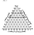
- the parameters x, y and z are on a polygonal line or inside the line (except on lines A'B' and C'D'), which connects points A', B', C' and D' in a ternary composition diagram of Fig. 3.
- the temperature coefficient ( ⁇ f) of the resonance frequency exceeds +50 ppm/°C
- white with x, y, and z outside the line B'C' the temperature coefficient ( ⁇ f) of the resonance frequency is shifted to the minus side from -50 ppm/°C.
- the reason for excluding the range on the line C'D' is the following.
- x With constant x, as z decreases, the temperature coefficient ( ⁇ f) of the resonance frequency is shifted to the minus side. Therefore, in order to obtain the same temperature coefficient ( ⁇ f) of the resonance frequency, it is necessary that x is increased as z is decreased.
- the rare earth element (Ln and Lm) Y, La, Pr, Nd, Sm, or the like is preferably used.
- La, Nd or Sm is more preferably used, and La is most preferably used.
- the use of Nd or Sm improves the Q value, and the use of La can further increase the dielectric constant ( ⁇ r ) and the Q value.
- high-purity calcium carbonate (CaCO 3 ), strontium carbonate (SrCO 3 ), titanium oxide (TiO 2 ), rare earth oxides (La 2 O 3 , and the like), magnesium oxide (MgO), and tantalum oxide (Ta 2 O 3 ) were prepared.
- These raw materials were also mixed to obtain compositions represented by the composition formula: XMTi a O 1+2a -yLn(Mg 2/3 Ta 1/3 ) b O (3+3b)/2 -zLm(Mg 1/2 Ti 1/2 ) c O (3+3c)/2 (wherein x, y and Z are by mol%) shown in Table 4.
- Samples 1041 to 1056 shown in Table 4 respectively contain the various rare earth elements shown in the column "Rare earth element” in Table 4 in place of La in the composition formula shown in Table 3, Samples 1041 to 1052 respectively have compositions corresponding to Sample 1016 shown in Table 3, and Samples 1053 to 1056 respectively have compositions corresponding to Sample 1035 shown in Table 3.
- a powder of these mixed raw materials was wet-milled for 16 hours by using a ball mill, dehydrated, dried and then calcined at 1100 to 1300°C for 3 hours.
- An appropriate amount of binder was added to the resultant calcined powder, and the mixture was again wet-ground for 16 hours by using the ball mill to obtain a powder.
- the thus-obtained powder was molded to a disk shape by using a press under a pressure of 1000 to 2000 kg/cm 2 , and then fired in the atmosphere at 1350 to 1450°C for 4 hours to obtain ceramic having a diameter of 10 mm and a thickness of 5 mm.
- the main crystal exhibited a perovskite crystal phase.
- Tables 3 and 4 indicate that the samples in the range of the present invention can exhibit high Q values while maintaining dielectric constants at high values in the microwave band.
- the reason for limiting a in the range of 0.950 ⁇ a ⁇ 1.050 is that with a ⁇ 0.950, like in Samples 1011 and 1030, and with 1.050 ⁇ a, like in Samples 1021 and 1040, the Q value is decreased, failing to achieve the object of the present invention.
- the reason for limiting b in the range of 0.900 ⁇ a ⁇ 1.050 is that with b ⁇ 0.900, like in Samples 1013 and 1032, and with b > 1.050, like in Samples 1019 and 1038, the Q value is decreased.
- the reason for limiting c in the range of 0.900 ⁇ a ⁇ 1.050 is that with c ⁇ 0.900, like in Samples 1015 and 1034, and with c > 1.050, like in Samples 1017 and 1036, the Q value is decreased.
- the temperature coefficient ( f) of the resonance frequency exceeds +50 ppm/°C
- the temperature coefficient ( f) of the resonance frequency is shifted to the minus side from -50 ppm/°C.
- the reason for excluding the range on the line C'D' is the following.
- the temperature coefficient ( ⁇ f) of the resonance frequency is shifted to the minus side.
- this property is exhibited in Samples 1004 to 1006, 1016, 1022 and 1023 shown in Table 3. Therefore, in order to obtain the same temperature coefficient ( ⁇ f) of the resonance frequency, it is necessary that x is increased as z is decreased.
- the Q value is decreased by increasing x, and thus x is as low as possible for obtaining a high Q value.
- comparison between Samples 1008 and 1016 shown in Table 3, which show substantially the same temperature coefficient of the resonance frequency indicates that in Sample 1016 having high z, a higher Q value is obtained.
- Comparison of Sample 1016 shown in Table 3 with Samples 1041 to 1052 shown in Table 4, and comparison of Sample 1005 shown in Table 3 with Samples 1053 to 1056 shown in Table 4 indicate that it is most preferable to use La as the rare earth element.
- the use of La can obtain both high dielectric constant ( ⁇ r ) and high Q value.
- Comparison between Samples 1041, 1044, 1047, and 1050 indicates that the use of Nd or Sm as a rare earth element can obtain a higher Q value, as compared with the use of Y or Pr.
- small amounts of additives may be added in ranges having no adverse effect on the object of the present invention.
- addition of 0.01 to 0.1 % by weight of SiO 2 , MnCO 3 , B 2 O 3 , ZnO, NiO, CuO, Li 2 CO 3 , or the like decreases the firing temperature by 20 to 30°C, while suppressing deterioration in characteristics.
- addition of 1 to 3 % by weight of ZrO 2 , SnO 2 , Nb 2 O 5 , WO 3 , or the like permits fine control of the dielectric constant ( ⁇ r ) and temperature characteristic, thereby obtaining excellent dielectric ceramic.
- the present invention can provide a high-frequency dielectric ceramic composition having a high dielectric constant ( ⁇ r ) of as high as 37 to 51, and a Q value of as high as 20, 000 (at 1GHz) or more, and permitting fine control of the temperature coefficient ( ⁇ f) of the resonance frequency to any desired values with 0 (ppm/°C) as a center.
- ⁇ r high dielectric constant
- ⁇ f temperature coefficient
- dielectric ceramic having the above-described composition can be used for manufacturing a dielectric resonator, a dielectric filter, a dielectric duplexer, and a communication device, each having good characteristics.
- Another high-frequency dielectric ceramic composition comprises a rare earth element (Ln and Lm), Mg, Ta, Sb, Ti and M (M: at least one of Ca and Sr), and has a composition represented by the composition formula, xMTi a O 1+2a -yLn(Mg 2/3 Ta 1/3 ) b O (3+3b)/2 -zLm(Mg 2/3 Sb 1/3 ) c O (3+3c)/2 (wherein x, y and Z are by mol%), wherein a, b, c, x, y and z are respectively in the following ranges.
- the parameter a is in the range of 0.950 ⁇ a ⁇ 1.050. This is because with a ⁇ 0.950, or a > 1.050, the Q value is decreased, failing to achieve the object of the present invention.
- the parameter b is in the range of 0.900 ⁇ a ⁇ 1.050. This is because with b ⁇ 0.900, or b > 1.050, the Q value is decreased.
- the parameter c is in the range of 0.900 ⁇ c ⁇ 1.050. This is because with c ⁇ 0.900, or c > 1.050, the Q value is decreased.
- the parameters x, y and z are on a polygonal line or inside the line (except on line C"D"), which connects points A", B", C" and D" in a ternary composition diagram of Fig. 4.
- the temperature coefficient ( f) of the resonance frequency exceeds +50 ppm/°C
- the temperature coefficient ( f) of the resonance frequency is shifted to the minus side from -50 ppm/°C.
- the rare earth element (Ln and Lm) Y, La, Pr, Nd, Sm, or the like is preferably used.
- La, Nd or Sm is more preferably used, and La is most preferably used.
- the use of Nd or Sm improves the Q value, and the use of La can further increase the dielectric constant ( ⁇ r ) and the Q value.
- high-purity calcium carbonate (CaCO 3 ), strontium carbonate (SrCO 3 ), titanium oxide (TiO 2 ), rare earth oxides (La 2 O 3 , and the like), magnesium oxide (MgO), tantalum oxide (Ta 2 O 3 ), and antimony oxide (Sb 2 O 3 ) were prepared.
- compositions represented by the composition formula xMTi a O 1+2a -yLa(Mg 2/3 Ta 1/3 ) b O (3+3b)/2 -zLa(Mg 2/3 Sb 1/3 ) c O (3+3c)/2 (wherein x, y and Z are by mol%) shown in Table 5.
- These raw materials were also mixed to obtain compositions represented by the composition formula, XMTi a O 1+2a -XLn(Mg 2/3 Ta 1/3 ) b O (3+3b)/2 -zLm(Mg 2/3 Sb 1/3 ) c O (3+3c)/2 (wherein x, y and Z are by mol%) shown in Table 6.
- Samples 2041 to 2056 shown in Table 6 respectively contain the various rare earth elements shown in the column "Rare earth element” in Table 6 in place of La in the composition formula shown in Table 5, Samples 2041 to 2052 respectively have compositions corresponding to Sample 2016 shown in Table 5, and Samples 2053 to 2056 respectively have compositions corresponding to Sample 2035 shown in Table 5.
- a powder of these mixed raw materials was wet-milled for 16 hours by using a ball mill, dehydrated, dried and then calcined at 1100 to 1300°C for 3 hours.
- An appropriate amount of binder was added to the resultant calcined powder, and the mixture was again wet-ground for 16 hours by using the ball mill to obtain a powder.
- the thus-obtained powder was molded to a disk shape by using a press under a pressure of 1, 000 to 2, 000 kg/cm 2 , and then fired in the atmosphere at 1350 to 1400°C for 4 hours to obtain ceramic having a diameter of 10 mm and a thickness of 5 mm and composed of a perovskite crystal phase as a main crystal.
- Tables 5 and 6 indicate that the samples in the range of the present invention can exhibit high Q values while maintaining dielectric constants at high values in the microwave band.
- the reason for limiting a in the range of 0.950 ⁇ a ⁇ 1.050 is that with a ⁇ 0.950, like in Samples 2011 and 2030, and with a > 1.050, like in Samples 2021 and 2040, the Q value is decreased, failing to achieve the object of the present invention.
- the reason for limiting b in the range of 0.900 ⁇ a ⁇ 1.050 is that with b ⁇ 0.900, like in Samples 2013 and 2032, and with 1.050 ⁇ b, like in Samples 2019 and 2038, the Q value is decreased.
- the reason for limiting c in the range of 0.900 ⁇ a ⁇ 1.050 is that with c ⁇ 0.900, like in Samples 2015 and 2034, and with 1.050 ⁇ c, like in Samples 2017 and 2036, the Q value is decreased.
- the temperature coefficient ( f) of the resonance frequency exceeds +50 ppm/°C
- the temperature coefficient ( f) of the resonance frequency is shifted to the minus side from -50 ppm/°C.
- Comparison of Sample 2016 shown in Table 5 with Samples 2041 to 2052 shown in Table 6, and comparison of Sample 2035 shown in Table 5 with Samples 2053 to 2056 shown in Table 6 indicate that it is most preferable to use La as the rare earth element.
- the use of La can obtain both high dielectric constant ( ⁇ r ) and high Q value.
- Comparison between Samples 2041, 2044, 2047, and 2050 indicates that the use of Nd or Sm as a rare earth element can obtain a higher Q value, as compared with the use of Y or Pr.
- small amounts of additives may be added in ranges having no adverse effect on the object of the present invention.
- addition of 0.01 to 0.1 % by weight of SiO 2 , MnCO 3 , B 2 O 3 , ZnO, NiO, CuO, Li 2 CO 3 , or the like decreases the firing temperature by 10 to 20°C, while suppressing deterioration in characteristics.
- addition of 1 to 3 % by weight of Nb 2 O 5 , V 2 O 5 , WO 3 , or the like permits fine control of the dielectric constant ( ⁇ r ) and temperature characteristic, thereby obtaining excellent dielectric ceramic.
- the present invention can provide a high-frequency dielectric ceramic composition having a high dielectric constant ( ⁇ r ) of as high as 37 to 54, and a Q value of as high as 20000 (at 1GHz) or more, and permitting fine control of the temperature coefficient ( f) of the resonance frequency to any desired values with 0 (ppm/°C) as a center.
- dielectric ceramic having the above-described composition can be used for manufacturing a dielectric resonator, a dielectric filter, a dielectric duplexer, and a communication device, each having good characteristics.
Abstract
Description
- The present invention relates to a high-frequency dielectric ceramic composition and electronic devices using the same.
- For example, dielectric ceramics are widely used as materials for a dielectric resonator, a dielectric filter, a circuit board, etc., which are mounted on electronic apparatuses used in a high-frequency region such as a microwave or millimeter wave region, or the like, such as a cellular telephone, a personal communication equipment, a satellite broadcasting receiver, etc.
- Dielectric characteristics required for such high-frequency dielectric ceramics include (1) a high dielectric constant (εr) for complying with the need for miniaturization because the wavelength of electromagnetic waves is shortened to 1/(εr)1/2 in a dielectric material, (2) a low dielectric loss, i.e., a high Q value, (3) excellent temperature stability of resonance frequency, i.e., the temperature coefficient (f) of the resonance frequency of about 0 (ppm/°C), etc.

- Examples of conventional known dielectric ceramic compositions include dielectric ceramic compositions such as Ba(Zn, Ta)O3 system compositions (Japanese Patent Publication No. Sho-58-25068), Ba(Sn, Mg, Ta)O3 system compositions (Japanese Patent Publication No. Hei-3-341 64), (Zr, Sn)TiO4 system compositions (Japanese Patent Publication No. Hei-4-59267), Ba2Ti9O20 (Japanese Laid-open Patent Application No. Sho-61-10806).
- However, Ba(Zn, Ta)O3 based and Ba(Sn, Mg, Ta)O3 based materials have a high Q value of 150, 000 to 300, 000 (at 1 GHz) but have a relatively low dielectric constant (εr) of 24 to 30.
- On the other hand, (Zr, Sn)TiO4 based materials and Ba2Ti9O20 have a relatively high dielectric constant (εr) of 37 to 40, and a high Q value of 50, 000 to 60, 000 (at 1 GHz), but it is difficult to realize a relatively high dielectric constant (εr) of over 40, for example.
- There has recently been increasing demand for decreasing the loss and miniaturizing electronic apparatus, and accordingly, there has been increasing demand for developing dielectric materials having excellent dielectric characteristics, particularly, both a high dielectric constant (εr) and a high Q value. However, at present, it is impossible to satisfactorily comply with these demands.
- Accordingly, it is one object of the present invention to provide a high-frequency dielectric ceramic composition having a relatively high dielectric constant (εr) of, for example, 25 to 60 and a high Q value of, for example, 15, 000 (at 1 GHz), and permitting arbitrary control of the temperature coefficient of the resonance frequency to about 0 ((ppm/°C), and a dielectric resonator comprising the dielectric ceramic composition.
- In order to solve the above-described technical problems, a high-frequency dielectric ceramic composition of the present invention comprises a rare earth element (Ln), Mg, Ta, Ti, and M (M: at least one of Ca and Sr), and has a composition represented by the composition formula by molar ratio, aLnOx/2-bMgO-cTaO5/2-dMO-eTiO2, wherein a, b, c, d, e and x are in the ranges of 0.100 ≤ a ≤ 0.350, 0.067 ≤ b ≤ 0.233, 0.033 ≤ c ≤ 0.117, 0.150 ≤ d ≤ 0.400, 0.150 ≤ e ≤ 0.400,
- The above ratios a, b, c, d, e, and x are preferably in the ranges of 0.150 ≤ a ≤ 0.200, 0.100 ≤ b ≤ 0.133, 0.050 ≤ c ≤ 0.067, 0.300 ≤ d ≤ 0.350, 0.300 ≤ e ≤ 0.350,
- Another high-frequency dielectric ceramic composition of the present invention comprises a rare earth element (Ln), Mg, Ta, Ti, and M (M: at least one of Ca and Sr), and has a composition represented by the composition formula by molar ratio, yLn(Mg2/3Ta1/3)O3-(1-y)MTiO3, wherein y is in the range of 0.2 ≤ y ≤ 0.7.
- The rare earth element (Ln) is preferably at least one of Y, La, Ce, Pr, Nd, Sm, Dy and Er, more preferably La.
- Still another preferred high-frequency dielectric ceramic composition comprises a rare earth element (Ln and Lm), Mg, Ta, Ti, and M (M: at least one of Ca and Sr), and has a composition represented by the composition formula by molar ratio, XMTiaO1+2a-yLn(Mg2/3Ta1/3)bO(3+3b)/2-zLm(Mg1/2Ti1/2)cO(3+3c)/2 (wherein x, y and Z are by mol%); wherein a, b, and c are in the ranges of 0.950 ≤ a ≤ 1.050, 0.900 ≤ b ≤ 1.050, and 0.900 ≤ c ≤ 1.050; x, y and z are on a polygonal line or inside the line (except on lines A'B' and C'D') which connects point A' (x = 70, y = 0, z = 30), point B' (x = 50, y = 0, Z = 50), point C' (x = 50, y = 50, z = 0) and point D' (x = 70, y = 30 z, = 0) in a ternary composition diagram of Fig. 3.
- The rare earth element (Ln, Lm) is preferably at least one of Y, La, Pr, Nd, and Sm.
- The element M is preferably Ca.
- The rare earth element (Ln, Lm) is more preferably at least one of La, Nd, and Sm.
- The rare earth element (Ln, Lm) is most preferably La.
- A further preferred high-frequency dielectric ceramic composition comprises a rare earth element (Ln or Lm), Mg, Ta, Sb, Ti, and M (M: at least one of Ca and Sr), and has a composition represented by the composition formula by molar ratio, xMTiaO1+2a-yLn(Mg2/3Ta1/3)bO(3+3b)/2-zLm(Mg2/3Sb1/3)cO(3+3c)/2(wherein x, y and Z are by mol%); wherein a, b, and c are in the ranges of 0.950 ≤ a ≤ 1.050, 0.900 ≤ b ≤ 1.050, and 0.900 ≤ c ≤ 1.050, respectively; X, Y and Z are on a polygonal line or inside the line (except on line C''D''), which connects point A'' (x = 75, y = 0, z = 25), point B'' (x = 55, y = 0, Z = 45), point C'' (x = 55, y = 45, z = 0) and point D'' (x = 75, y = 25 z, = 0), in a ternary composition diagram of Fig. 4.
- The rare earth element (Ln, Lm) is at least one of Y, La, Pr, Nd, and Sm.
- The element M is preferably Ca.
- The rare earth element (Ln, Lm) is preferably at least one of La, Nd, and Sm.
- The rare earth element (Ln, Lm) is most preferably La.
- A dielectric resonator of the present invention is operated by electromagnetic field coupling of dielectric ceramic with input/output terminals, wherein the dielectric ceramic is composed of any one of the above-described high-frequency dielectric ceramic compositions.
- A dielectric filter of the present invention comprises the above dielectric resonator including external coupling means.
- A dielectric duplexer of the present invention comprises at least two dielectric filters, input/output connecting means connected to each of the dielectric filters, and antenna connecting means connected to the dielectric filters in common, wherein at least one of the dielectric filters is the above-described dielectric filter.
- A communication device of the present invention comprises the above dielectric duplexer, a transmitting circuit connected to at least one input/output connecting means of the dielectric duplexer, a receiving circuit connected to at least one input/output connecting means different from the input/output connecting means connected to the transmitting circuit, and an antenna connected to antenna connecting means of the dielectric duplexer.
-
- Fig. 1 is a sectional view of a dielectric resonator of the present invention;
- Fig. 2 is a block diagram of a communication device of the present invention;
- Fig. 3 is a ternary composition diagram of MTiO3-Ln(Mg2/3Ta1/3)O3-Lm(Mg1/2Ti1/2)O3 system compositions; and
- Fig. 4 is a ternary composition diagram of MTiO3-Ln(Mg2/3Ta1/3)O3-Lm(Mg2/3Sb1/3)O3 system compositions.
-
- Fig. 1 is a sectional view showing the fundamental structure of a
dielectric resonator 1 comprising a ceramic composition of the present invention. - The
dielectric resonator 1 comprising ametallic case 2, and a columnar dielectric ceramic 4 arranged in the space of the metallic case to be supported by asupport 3. Input andoutput terminal metallic case 2 in a state insulated from themetallic case 2. - The
dielectric ceramic 4 is operated by electromagnetic field coupling with the input andoutput terminals input terminal 5 are output from theoutput terminal 6. - The dielectric ceramic 4 provided in the
dielectric resonator 1 is composed of a high-frequency dielectric ceramic composition of the present invention. - Fig. 2 is a block diagram showing an example of communication devices of the present invention. A
communication device 10 comprises adielectric duplexer 12, a transmittingcircuit 14, areceiving circuit 16, and anantenna 18. The transmittingcircuit 14 is connected to input connecting means 20 of thedielectric duplexer 12; thereceiving circuit 16 is connected to output connecting means 22 of thedielectric duplexer 12. Theantenna 18 is connected to antenna connecting means 24 of thedielectric duplexer 12. Thedielectric duplexer 12 comprises twodielectric filters dielectric filters dielectric resonator 1. One 26 of thedielectric filters dielectric filter 28; the otherdielectric filter 28 is connected between one 26 of thedielectric filters - As described above, the high-frequency dielectric ceramic composition of the present invention comprises a rare earth element (Ln), Mg, Ta, Ti, and M (M: at least one of Ca and Sr), and has a composition represented by the composition formula by molar ratio, aLnOx/2-bMgO-cTaO5/2-dMO-eTiO2 wherein
- First, a is selected in the range of 0.100 ≤ a ≤ 0.350. This is because with a < 0.100, the Q value is decreased, while with 0.350 < a, the absolute value of the temperature coefficient (τf) of the resonance frequency exceeds 80 ppm/°C.
- The parameter a is more preferably selected in the range of 0.150 ≤ a ≤ 0.200 because it is possible to obtain the characteristic that the temperature coefficient (τf) of the resonance frequency is 28 ppm/°C or less.
- The parameters b and c are selected in the ranges of 0.067 ≤ b ≤ 0.233 and 0.033 ≤ c ≤ 0.117, respectively. This is because with b < 0.067 or c < 0.033, the Q value is decreased, while with 0.233 < b or 0.117 < c, the absolute value of the temperature coefficient (τf) of the resonance frequency exceeds 80 ppm/°C.
- More preferably, b is limited in the range of 0.100 ≤ b ≤ 0.133, and c is limited in the range of 0.050 ≤ c ≤ 0.067 because it is possible to obtain the characteristic that the temperature coefficient (τf) of the resonance frequency is 28 ppm/°C or less.
- The parameter d is selected in the range of 0.150 ≤ d ≤ 0.400. This is because with d > 0.400, the Q value is decreased, while with d < 0.150, the absolute value of the temperature coefficient (τf) of the resonance frequency exceeds 80 ppm/°C.
- More preferably d is in the range of 0.300 ≤ d ≤ 0.350 because it is possible to obtain the characteristic that the temperature coefficient (τf) of the resonance frequency is 28 ppm/°C or less.
- The parameter e is in the range of 0.150 ≤ e ≤ 0.400. This is because with 0.400 < e, the Q value is decreased, while with e < 0.150, the absolute value of the temperature coefficient (τf) of the resonance frequency exceeds 80 ppm/°C.
- The parameter e is more preferably selected in the range of 0.300 ≤ e ≤ 0.350 because it is possible to obtain the characteristic that the temperature coefficient (τf) of the resonance frequency is 28 ppm/°C or less.
- In the high-frequency dielectric ceramic composition of the present invention, as the rare earth element (Ln), at least one of Y, La, Ce, Pr, Nd, Sm, Dy and Er can be used. Of these elements, La is more preferably used. This is because the use of La can increase the dielectric constant (εr) and Q value as compared with the other elements.
- In the high-frequency dielectric ceramic composition of the present invention, small amounts of additives may be added in ranges having no adverse effect on the object of the present invention. For example, addition of 0.01 to 0.1 % by weight of SiO2, ZnO, MnO, B2O3, NiO, CuO, Li2CO3, or the like decreases the firing temperature by 20 to 30°C, but deteriorates less characteristics. Also addition of 1 to 3 % by weight of Al2O3, Sb2O3, V2O5, WO3, or the like permits fine control of the dielectric constant and temperature characteristic, thereby obtaining excellent dielectric ceramic.
- The high-frequency dielectric ceramic composition of the present invention is represented by the composition formula yLn(Mg2/3Ta1/3)O3-(1-y)MTiO3 more specific than the above composition formula by molar ratio, and y can be changed in the range of 0.2 ≤ y ≤ 0.7 to change the temperature coefficient (τf) of the resonance frequency to any desired values with 0 (ppm/°C) as the center. In this case, the dielectric constant (εr) is as high as 25 to 60, and the Q value is 15, 000 or more.
- The present invention will be described below based on examples.
- As starting raw materials, high-purity rare earth oxides (La2O3, and the like), magnesium oxide (MgO), tantalum oxide (Ta2O3), calcium carbonate (CaCO3), strontium carbonate (SrCO3), and titanium oxide (TiO2) were prepared, and these materials were mixed at the composition ratios shown in Tables 1 and 2.

Sample No. Rare earth Element (Ln) Dielectric Constant εr Q Value 1GHz Temperature coefficient of resonance frequency Remarks 53 Y 36.6 15100 -4 Composition corresponding to Sample 17 shown in Table 1 54 0.1Y·0.9La 43.0 29800 -8 55 0.3Y·0.7La 40.5 25300 -6 56 0.5Y·0.5La 38.1 22400 -5 57 0.5Co·0.5La 42.0 18000 -5 58 Nd 42.5 16200 -7 59 0.1Nd·0.9La 44.1 29000 -8 60 0.3Nd·0.7La 43.8 24300 -7 61 0.5Nd·0.5La 43.3 19500 -7 62 0.5Pr·0.5La 42.5 17900 -6 63 Sm 37.2 32600 -3 64 0.1Sm·0.9La 43.9 34200 -9 65 0.3Sm·0.7La 42.3 34000 -8 66 0.5Sm·0.5La 40.4 34100 -5 67 0.5Dy·0.5La 41.2 29500 -4 68 0.5Er·0.5La 39.8 28400 -6 69 Y 37.0 15100 10 Composition corresponding to Sample 48 shown in Table 1 70 0.5Y·0.5La 39.7 18600 8 71 Nd 44.3 15800 7 72 0.5Nd·0.5La 45.2 20200 8 73 Sm 39.5 23700 10 74 0.5Sm·0.5La 44.0 25000 9 - In Table 1, y represents the ratio of Ln(Mg2/3T1/3)O3 to MTiO3 in the composition formula: yLn(Mg2/3Ta1/3)O3-(1-y)MTiO3.
- In Table 1, a, b, c, d, and e respectively represent the molar ratios of the components in the composition by molar ratio: aLnOx/2-bMgO-cTaO5/2-dMO-eTiO2 (wherein M is Ca and/or Sr).
- Samples 53 to 74 shown in Table 2 respectively contain the various rare earth element oxides shown in the column "Rare earth element" in place of La2O3 shown in Table 1, Samples 53 to 68 respectively have compositions corresponding to Sample 17 shown in Table 1, and Samples 69 to 74 respectively have compositions corresponding to Sample 48 shown in Table 1.
- In Table 1, Samples Nos. marked with an asterisk * are beyond the range of the present invention.
- A powder prepared at each of the composition ratios shown in Tables 1 and 2 was wet-milled for 16 hours by using a ball mill, dehydrated, dried and then calcined at 1100 to 1300°C for 3 hours. An appropriate amount of binder was added to the resultant calcined powder, and the mixture was again ground for 16 hours by using the ball mill to obtain a powder.
- The thus-obtained powder was molded to a disk shape by using a press under a pressure of 1, 000 to 2, 000 kg/cm2, and then fired in the atmosphere at 1, 400 to 1, 500°C for 4 to 10 hours to obtain a sintered compact having a diameter of 10 mm and a thickness of 5 mm.
- The thus-obtained sintered compact was measured with respect to the dielectric constant (εr) at a measurement frequency of 6 to 8 GHz, and the Q value by a double-end short-circuit type dielectric resonator method, and the measurements were converted to a Q value at 1 GHz according to the law:
- Tables 1 and 2 indicate that the samples in the range of the present invention can exhibit high Q values while maintaining dielectric constants at high values in the microwave band.
- The reasons for respectively limiting the molar ratios a, b, c, d, and e in the ranges of the present invention will be described mainly with reference to Table 1.
- First, the reason for limiting a in the range of 0.100 ≤ a ≤ 0.350 is that with a < 0.100, like in
Samples - The reason why the range of 0.150 ≤ a ≤ 0.200 is preferable is that like in
Samples 10 to 23 and 47 to 52, the absolute value of the temperature coefficient (τf) of the resonance frequency is 28 ppm/°C or less. - The reason for limiting b in the range of 0.067 ≤ b ≤ 0.233 is that with b < 0.067, like in
Samples - The reason why the range of 0.100 ≤ b ≤ 0.133 is preferable is that like in
Samples 10 to 23, 38, and 47 to 52, the absolute value of the temperature coefficient (τf) of the resonance frequency is 28 ppm/°C or less. - The reason for limiting c in the range of 0.033 ≤ c ≤ 0.117 is that with c < 0.033, like in
Samples 1,7, and 8, the Q value is decreased, while with c > 0.117, like inSamples 29, 30, 36, 37, 46 and 46, the absolute value of the temperature coefficient (τf) of the resonance frequency exceeds 80 ppm/°C. - The reason why the range of 0.050 ≤ c ≤ 0.067 is preferable is that like in
Samples 10 to 23, 38, and 47 to 52, the absolute value of the temperature coefficient (τf) of the resonance frequency is 28 ppm/°C or less. - The reason for limiting d in the range of 0.150 ≤ a ≤ 0.400 is that with d > 0.400, like in
Samples - The reason why the range of 0.300 ≤ d ≤ 0.350 is preferable is that like in
Samples 10 to 23, 38, and 47 to 52, the absolute value of the temperature coefficient (τf) of the resonance frequency is 28 ppm/°C or less. - The reason for limiting e in the range of 0.150 ≤ a ≤ 0.400 is that with e > 0.400, like in
Samples - The reason why the range of 0.300 ≤ e ≤ 0.350 is preferable is that like in
Samples 10 to 23, 38, and 47 to 52, the absolute value of the temperature coefficient (τf) of the resonance frequency is 28 ppm/°C or less. - Comparison of Sample 17 shown in Table 1 with Samples 53 to 68 shown in Table 2 indicates that it is preferable to use La as the rare earth element. The use of La can further increase both the dielectric constant (εr) and the Q value.
- In Table 1, Samples having "y" values described in the table have compositions represented by the composition formula: yLn(Mg2/3Ta1/3)O3-(1-y)MTiO3 and the main crystal is composed of a perovskite crystal phase. However, comparison between
Samples 5, 9 to 12, 17, 23 to 28, 32, 38 to 44, and 47 to 52 reveals that the temperature coefficient (τf) of the resonance frequency can be changed to any desired values with 0 ppm/°C as a center by changing y in the range of 0.2 ≤ y ≤ 0.7. These samples exhibit dielectric constants (εr) of as high as about 25 to 60, and most of the samples exhibit Q values of 15000 or more. - As described above, the present invention can provide a high-frequency dielectric ceramic composition having both a high dielectric constant and high Q value, and permitting a decrease in the temperature coefficient (τf) of the resonance frequency, and a dielectric ceramic obtained by sintering the composition can be advantageously used for high-frequency devices such as a dielectric resonator, etc.
- The high-frequency dielectric ceramic composition of the present invention has a composition represented by the composition formula: yLn(Mg2/3Ta1/3)O3-(1-y)MTiO3 (wherein Ln is a rare earth element, and M is at least one of Ca and Sr), wherein y is in the range of 0.2 ≤ y ≤ 0.7. The main crystal is composed of a perovskite crystal phase. In this case, y can be changed to control the temperature coefficient (τf) of the resonance frequency to any desired values with 0 (ppm/°C) as a center.
- A high-frequency dielectric ceramic composition comprises a rare earth element (Ln and Lm), Mg, Ta, Ti and M (M: at least one of Ca and Sr), and has a composition represented by the composition formula: xMTiaO1+2a-yLn(Mg2/3Ta1/3)bO(3+3b)/2-zLm(Mg1/2Ti1/2)cO(3+3c)/2 (wherein x, y and Z are by mol%), wherein a, b, c, x, y and z are respectively in the following ranges.
- The parameter a is in the range of 0.850 ≤ a ≤ 1.050. This is because with a < 0.950, or a > 1.050, the Q value is decreased, failing to achieve the object of the present invention.
- The parameter b is in the range of 0.900 ≤ a ≤ 1.050. This is because with b < 0.900, or b > 1.050, the Q value is decreased.
- The parameter c is in the range of 0.900 ≤ c ≤ 1.050. This is because with c < 0.900, or c > 1.050, the Q value is decreased.
- The parameters x, y and z are on a polygonal line or inside the line (except on lines A'B' and C'D'), which connects points A', B', C' and D' in a ternary composition diagram of Fig. 3. With x, y and z outside the line A'D', the temperature coefficient (τf) of the resonance frequency exceeds +50 ppm/°C, white with x, y, and z outside the line B'C', the temperature coefficient (τf) of the resonance frequency is shifted to the minus side from -50 ppm/°C. The reason for except on the line A'B' is that with y = 0, the composition cannot be sufficiently sintered at a firing temperature of 1, 350 to 1, 450°C, and thus, firing at a high temperature of over 1, 500°C is required, thereby causing many disadvantages for industrial mass production.
- The reason for excluding the range on the line C'D' is the following. With constant x, as z decreases, the temperature coefficient (τf) of the resonance frequency is shifted to the minus side. Therefore, in order to obtain the same temperature coefficient (τf) of the resonance frequency, it is necessary that x is increased as z is decreased. However, there is the property that the Q value is decreased by increasing x, and thus x is as low as possible for obtaining a high Q value. For this reason, the range on the line C'D' is excluded because the effect of decreasing x, i.e., the effect of improving the Q value, cannot be expected, but characteristics less deteriorate with z = 0. Since tantalum oxide (Ta2O3) as a starting raw material is an expensive material, a composition containing much tantalum oxide is undesirable from the viewpoint of industrial application.
- In the high-frequency dielectric ceramic composition of the present invention, as the rare earth element (Ln and Lm), Y, La, Pr, Nd, Sm, or the like is preferably used. However, of these elements, La, Nd or Sm is more preferably used, and La is most preferably used. The use of Nd or Sm improves the Q value, and the use of La can further increase the dielectric constant (εr) and the Q value.
- The present invention will be in further detail below.
- As starting raw materials, high-purity calcium carbonate (CaCO3), strontium carbonate (SrCO3), titanium oxide (TiO2), rare earth oxides (La2O3, and the like), magnesium oxide (MgO), and tantalum oxide (Ta2O3) were prepared.
- These raw materials were mixed to obtain compositions represented by the composition formula: xMTiaO1+2a-yLa(Mg2/3Ta1/3)bO(3+3b)/2-zLa(Mg1/2Ti1/2)cO(3+3c)/2 (wherein x, y and Z are by mol%) shown in Table 3. These raw materials were also mixed to obtain compositions represented by the composition formula: XMTiaO1+2a-yLn(Mg2/3Ta1/3)bO(3+3b)/2-zLm(Mg1/2Ti1/2)cO(3+3c)/2 (wherein x, y and Z are by mol%) shown in Table 4.
xMTiaO1+2a-yLa(Mg2/3Ta1/3)bO(3+3b)/2-zLa(Mg1/2Ti1/2)oO(3+3c)/2 System Sample No. M a b c x y z Dielectric Constant εr Q Value 1GHz Temperature coefficient of frequency *1001 Ca 1.000 1.000 1.000 75.0 5.0 20.0 58.8 29300 +57 *1002 Ca 1.000 1.000 1.000 75.0 20.0 5.0 56.6 30500 +51 *1003 Ca 1.000 1.000 1.000 70.0 0.0 30.0 Poor sintering 1004 Ca 1.000 1.000 1.000 70.0 10.0 20.0 51.1 34200 +32 1005 Ca 1.000 1.000 1.000 70.0 20.0 10.0 50.2 34800 +26 *1006 Ca 1.000 1.000 1.000 70.0 30.0 0.0 49.4 35400 +20 1007 Ca 1.000 1.000 1.000 65.0 10.0 25.0 47.0 36400 +3 1008 Ca 1.000 1.000 1.000 65.0 25.0 10.0 44.8 38200 -5 *1009 Ca 1.000 1.000 1.000 60.0 0.0 40.0 Poor sintering 1010 Ca 1.000 1.000 1.000 60.0 10.0 30.0 47.8 36300 +8 *1011 Ca 0.900 1.000 1.000 60.0 20.0 20.0 44.4 18600 -4 1012 Ca 0.950 1.000 1.000 60.0 20.0 20.0 44.5 32500 -3 *1013 Ca 1.000 0.850 1.000 60.0 20.0 20.0 44.2 19700 -3 1014 Ca 1.000 0.900 0.900 60.0 20.0 20.0 45.3 39000 -4 *1015 Ca 1.000 1.000 0.850 60.0 20.0 20.0 44.6 18900 -4 1016 Ca 1.000 1.000 1.000 60.0 20.0 20.0 45.4 39500 -4 *1017 Ca 1.000 1.000 1.100 60.0 20.0 20.0 44.7 17600 -3 1018 Ca 1.000 1.050 1.050 60.0 20.0 20.0 45.0 38500 -4 *1019 Ca 1.000 1.100 1.000 60.0 20.0 20.0 44.4 19000 -3 1020 Ca 1.050 1.000 1.000 60.0 20.0 20.0 44.6 29100 -3 *1021 Ca 1.100 1.000 1.000 60.0 20.0 20.0 43.7 16100 -2 1022 Ca 1.000 1.000 1.000 60.0 30.0 10.0 43.8 39600 -10 *1023 Ca 1.000 1.000 1.000 60.0 40.0 0.0 40.6 37600 -28 *1024 Ca 1.000 1.000 1.000 50.0 0.0 50.0 Poor sintering 1025 Ca 1.000 1.000 1.000 50.0 15.0 35.0 42.0 38900 -39 1026 Ca 1.000 1.000 1.000 50.0 35.0 15.0 36.9 42200 -45 *1027 Ca 1.000 1.000 1.000 50.0 50.0 0.0 34.8 45700 -52 *1028 Ca 1.000 1.000 1.000 45.0 15.0 40.0 31.8 48300 -63 *1029 Ca 1.000 1.000 1.000 45.0 40.0 15.0 29.0 50100 -74 *1030 0.7Ca0.3Sr 0.900 1.000 1.000 60.0 20.0 20.0 38.8 12300 1 1031 0.7Ca0.3Sr 0.950 1.000 1.000 60.0 20.0 20.0 38.9 20600 2 *1032 0.7Ca0.3Sr 1.000 0.850 1.000 60.0 20.0 20.0 38.8 18400 2 1033 0.7Ca0.3Sr 1.000 0.900 0.900 60.0 20.0 20.0 38.8 31500 1 *1034 0.7Ca0.3Sr 1.000 1.000 0.850 60.0 20.0 20.0 39.0 17600 1 1035 0.7Ca0.3Sr 1.000 1.000 1.000 60.0 20.0 20.0 39.0 31000 2 *1036 0.7Ca0.3Sr 1.000 1.000 1.100 60.0 20.0 20.0 38.8 16300 2 1037 0.7Ca0.3Sr 1.000 1.050 1.050 60.0 20.0 20.0 38.9 29200 2 *1038 0.7Ca0.3Sr 1.000 1.100 1.000 60.0 20.0 20.0 39.0 17600 1 1039 0.7Ca0.3Sr 1.050 1.000 1.000 60.0 20.0 20.0 38.8 26300 2 *1040 0.7Ca0.3Sr 1.100 1.000 1.000 60.0 20.0 20.0 38.9 10100 1 x MTiaO1+2a-yLn(Mg2/3Ta1/3)bO(3+3b)/2-zLm(Mg1/2Ti1/2)cO(3+3c)/2 Sample No. Rare earth Element (Ln, Lm) Dielectric Constant εr Q Value 1GHz Temperature coefficient of resonance frequency Remarks 1041 Y 42.9 36800 -7 Corresponding to Sample 1016 shown in Table 3 1042 0.1Y·0.9La 43.7 37800 -6 1043 0.3Y·0.7La 43.4 37200 -6 1044 Pr 43.8 37000 -8 1045 0.1Pr·0.9La 44.8 37600 -7 1046 0.3Pr·0.7La 44.0 37500 -7 1047 Nd 43.2 38800 -8 1048 0.1Nd·0.9La 44.2 39000 -7 1049 0.3Nd·0.7La 43.6 38700 -6 1050 Sm 42.0 39700 -4 1051 0.1Sm·0.9La 44.1 39100 -5 1052 0.3Sm·0.7La 43.2 39500 -6 1053 0.5Y0.5La 38.8 30400 2 1054 0.5Pr0.5La 38.7 30600 3 Corresponding to Sample 1035 shown in Table 3 1055 0.5Nd0.5La 38.5 31200 2 1056 0.5Sm0.5La 38.4 31300 4 - Samples 1041 to 1056 shown in Table 4 respectively contain the various rare earth elements shown in the column "Rare earth element" in Table 4 in place of La in the composition formula shown in Table 3, Samples 1041 to 1052 respectively have compositions corresponding to Sample 1016 shown in Table 3, and Samples 1053 to 1056 respectively have compositions corresponding to Sample 1035 shown in Table 3.
- A powder of these mixed raw materials was wet-milled for 16 hours by using a ball mill, dehydrated, dried and then calcined at 1100 to 1300°C for 3 hours. An appropriate amount of binder was added to the resultant calcined powder, and the mixture was again wet-ground for 16 hours by using the ball mill to obtain a powder.
- The thus-obtained powder was molded to a disk shape by using a press under a pressure of 1000 to 2000 kg/cm2, and then fired in the atmosphere at 1350 to 1450°C for 4 hours to obtain ceramic having a diameter of 10 mm and a thickness of 5 mm. The main crystal exhibited a perovskite crystal phase.
- The thus-obtained ceramic was measured with respect to the dielectric constant (εr) at a measurement frequency of 6 to 8 GHz, and the Q value by a double-end short-circuit type dielectric resonator method, and the measurements were converted to a Q value at 1 GHz according to the law: Q x f = constant. Also the temperature coefficient (τf) of the resonance frequency between 25°C and 55°C was measured from the TE01δ mode resonance frequency. The results are shown in Tables 3 and 4. In Table 3, Sample Nos. marked with an asterisk * are beyond the range of the present invention.
- Tables 3 and 4 indicate that the samples in the range of the present invention can exhibit high Q values while maintaining dielectric constants at high values in the microwave band.
- The reasons for limiting the composition represented by the composition formula of the present invention, xMTiaO1+2a-yLn(Mg2/3Ta1/3)bO(3+3b)/2-zLm(Mg1/2Ti1/2)cO(3+3c)/2 (wherein Ln and Lm are rare earth elements, and M is at least one of Ca and Sr), will be described mainly with reference to Table 3.
- First, the reason for limiting a in the range of 0.950 ≤ a ≤ 1.050 is that with a < 0.950, like in Samples 1011 and 1030, and with 1.050 < a, like in Samples 1021 and 1040, the Q value is decreased, failing to achieve the object of the present invention.
- The reason for limiting b in the range of 0.900 ≤ a ≤ 1.050 is that with b < 0.900, like in Samples 1013 and 1032, and with b > 1.050, like in Samples 1019 and 1038, the Q value is decreased.
- The reason for limiting c in the range of 0.900 ≤ a ≤ 1.050 is that with c < 0.900, like in Samples 1015 and 1034, and with c > 1.050, like in Samples 1017 and 1036, the Q value is decreased.
- The reasons for liming x, y and z in the region on the polygonal line or inside the line (except on the line A'B' and line C'D') which connects points A', B', C' and D' in a ternary composition diagram of Fig. 3 are as follows:
- In the region outside the line A'D', like in Samples 1001 and 1002, the temperature coefficient (
- The reason for excluding the range on the line C'D' is the following. With constant x, as z decreases, the temperature coefficient (τf) of the resonance frequency is shifted to the minus side. For example, this property is exhibited in Samples 1004 to 1006, 1016, 1022 and 1023 shown in Table 3. Therefore, in order to obtain the same temperature coefficient (τf) of the resonance frequency, it is necessary that x is increased as z is decreased. However, there is the property that the Q value is decreased by increasing x, and thus x is as low as possible for obtaining a high Q value. For example, comparison between Samples 1008 and 1016 shown in Table 3, which show substantially the same temperature coefficient of the resonance frequency, indicates that in Sample 1016 having high z, a higher Q value is obtained. For this reason, the range on the line C'D' is excluded because the effect of decreasing x, i.e., the effect of improving the Q value, cannot be expected, but characteristics less deteriorate with z = 0.
- Comparison of Sample 1016 shown in Table 3 with Samples 1041 to 1052 shown in Table 4, and comparison of Sample 1005 shown in Table 3 with Samples 1053 to 1056 shown in Table 4 indicate that it is most preferable to use La as the rare earth element. The use of La can obtain both high dielectric constant (εr) and high Q value. Comparison between Samples 1041, 1044, 1047, and 1050 indicates that the use of Nd or Sm as a rare earth element can obtain a higher Q value, as compared with the use of Y or Pr.
- In the high-frequency dielectric ceramic composition of the present invention, small amounts of additives may be added in ranges having no adverse effect on the object of the present invention. For example, addition of 0.01 to 0.1 % by weight of SiO2, MnCO3, B2O3, ZnO, NiO, CuO, Li2CO3, or the like decreases the firing temperature by 20 to 30°C, while suppressing deterioration in characteristics. Also addition of 1 to 3 % by weight of ZrO2, SnO2, Nb2O5, WO3, or the like permits fine control of the dielectric constant (εr) and temperature characteristic, thereby obtaining excellent dielectric ceramic.
- As described above, the present invention can provide a high-frequency dielectric ceramic composition having a high dielectric constant (εr) of as high as 37 to 51, and a Q value of as high as 20, 000 (at 1GHz) or more, and permitting fine control of the temperature coefficient (τf) of the resonance frequency to any desired values with 0 (ppm/°C) as a center.
- Therefore, dielectric ceramic having the above-described composition can be used for manufacturing a dielectric resonator, a dielectric filter, a dielectric duplexer, and a communication device, each having good characteristics.
- Another high-frequency dielectric ceramic composition comprises a rare earth element (Ln and Lm), Mg, Ta, Sb, Ti and M (M: at least one of Ca and Sr), and has a composition represented by the composition formula, xMTiaO1+2a-yLn(Mg2/3Ta1/3)bO(3+3b)/2-zLm(Mg2/3Sb1/3)cO(3+3c)/2 (wherein x, y and Z are by mol%), wherein a, b, c, x, y and z are respectively in the following ranges.
- The parameter a is in the range of 0.950 ≤ a ≤ 1.050. This is because with a < 0.950, or a > 1.050, the Q value is decreased, failing to achieve the object of the present invention.
- The parameter b is in the range of 0.900 ≤ a ≤ 1.050. This is because with b < 0.900, or b > 1.050, the Q value is decreased.
- The parameter c is in the range of 0.900 ≤ c ≤ 1.050. This is because with c < 0.900, or c > 1.050, the Q value is decreased.
- The parameters x, y and z are on a polygonal line or inside the line (except on line C"D"), which connects points A", B", C" and D" in a ternary composition diagram of Fig. 4. With x, y and z outside the line A"D", the temperature coefficient (
- In the high-frequency dielectric ceramic composition of the present invention, as the rare earth element (Ln and Lm), Y, La, Pr, Nd, Sm, or the like is preferably used. However, of these elements, La, Nd or Sm is more preferably used, and La is most preferably used. The use of Nd or Sm improves the Q value, and the use of La can further increase the dielectric constant (εr) and the Q value.
- The present invention will be in further detail below based on examples.
- As starting raw materials, high-purity calcium carbonate (CaCO3), strontium carbonate (SrCO3), titanium oxide (TiO2), rare earth oxides (La2O3, and the like), magnesium oxide (MgO), tantalum oxide (Ta2O3), and antimony oxide (Sb2O3) were prepared.
- These raw materials were mixed to obtain compositions represented by the composition formula, xMTiaO1+2a-yLa(Mg2/3Ta1/3)bO(3+3b)/2-zLa(Mg2/3Sb1/3)cO(3+3c)/2 (wherein x, y and Z are by mol%) shown in Table 5. These raw materials were also mixed to obtain compositions represented by the composition formula, XMTiaO1+2a-XLn(Mg2/3Ta1/3)bO(3+3b)/2-zLm(Mg2/3Sb1/3)cO(3+3c)/2 (wherein x, y and Z are by mol%) shown in Table 6.
xMTiaO1+2a-yLa(Mg2/3Ta1/3)bO(3+3b/2-zLa(Mg2/3Sb1/3)oO(3+3c)/2 System Sample No. M a b c x y z Dielectric Constant εr Q Value 1GHz Temperature coefficient of Resonance frequency *2001 Ca 1.000 1.000 1.000 80.0 5.0 15.0 58.2 22500 +65 *2002 Ca 1.000 1.000 1.000 80.0 15.0 5.0 58.9 21300 +68 2003 Ca 1.000 1.000 1.000 75.0 0.0 25.0 53.6 27600 +45 2004 Ca 1.000 1.000 1.000 75.0 15.0 10.0 53.8 25300 +45 *2005 Ca 1.000 1.000 1.000 75.0 25.0 0.0 Green Green Green 2006 Ca 1.000 1.000 1.000 70.0 10.0 20.0 49.1 35800 +20 2007 Ca 1.000 1.000 1.000 70.0 20.0 10.0 49.4 35400 +20 2008 Ca 1.000 1.000 1.000 67.5 12.5 20.0 46.8 37400 +4 2009 Ca 1.000 1.000 1.000 67.5 20.0 12.5 47.0 37000 +4 2010 Ca 1.000 1.000 1.000 65.0 0.0 35.0 43.1 37400 -9 *2011 Ca 0.900 1.000 1.000 65.0 17.5 17.5 43.7 17500 -9 2012 Ca 0.950 1.000 1.000 65.0 17.5 17.5 43.9 36000 -8 *2013 Ca 1.000 0.850 1.000 65.0 17.5 17.5 43.9 19300 -8 2014 Ca 1.000 0.900 0.900 65.0 17.5 17.5 44.0 36500 -8 *2015 Ca 1.000 1.000 0.850 65.0 17.5 17.5 43.9 18800 -7 2016 Ca 1.000 1.000 1.000 65.0 17.5 17.5 43.9 36300 -8 *2017 Ca 1.000 1.000 1.100 65.0 17.5 17.5 43.8 16100 -8 2018 Ca 1.000 1.050 1.050 65.0 17.5 17.5 44.0 36200 -7 *2019 Ca 1.000 1.100 1.000 65.0 17.5 17.5 43.9 15600 -8 2020 Ca 1.050 1.000 1.000 65.0 17.5 17.5 43.9 32400 -8 *2021 Ca 1.100 1.000 1.000 65.0 17.5 17.5 43.8 12900 -7 *2022 Ca 1.000 1.000 1.000 65.0 35.0 0.0 Green Green Green 2023 Ca 1.000 1.000 1.000 60.0 15.0 25.0 40.4 38000 -28 2024 Ca 1.000 1.000 1.000 60.0 25.0 15.0 40.6 37900 -28 2025 Ca 1.000 1.000 1.000 55.0 0.0 45.0 36.7 43400 -42 2026 Ca 1.000 1.000 1.000 55.0 22.5 22.5 37.2 41200 -40 *2027 Ca 1.000 1.000 1.000 55.0 45.0 0.0 Green Green Green *2028 Ca 1.000 1.000 1.000 50.0 15.0 35.0 34.2 46100 -58 *2029 Ca 1.000 1.000 1.000 50.0 35.0 15.0 34.8 45700 -56 *2030 0.8Ca0.2Sr 0.900 1.000 1.000 65.0 25.0 10.0 43.5 12400 -3 2031 0.8Ca0.2Sr 0.950 1.000 1.000 65.0 25.0 10.0 43.5 29700 -4 *2032 0.8Ca0.2Sr 1.000 0.850 1.000 65.0 25.0 10.0 43.6 15200 -3 2033 0.8Ca0.2Sr 1.000 0.900 0.900 65.0 25.0 10.0 43.5 32000 -4 *2034 0.8Ca0.2Sr 1.000 1.000 0.850 65.0 25.0 10.0 43.6 14500 -4 2035 0.8Ca0.2Sr 1.000 1.000 1.000 65.0 25.0 10.0 43.6 31800 -4 *2036 0.8Ca0.2Sr 1.000 1.000 1.100 85.0 25.0 10.0 43.5 16200 -3 2037 0.8Ca0.2Sr 1.000 1.050 1.050 65.0 25.0 10.0 43.5 31100 -3 *2038 0.8Ca0.2Sr 1.000 1.100 1.000 65.0 25.0 10.0 43.6 17800 -4 2039 0.8Ca0.2Sr 1.050 1.000 1.000 65.0 25.0 10.0 43.6 28000 -4 *2040 0.8Ca0.2Sr 1.100 1.000 1.000 65.0 25.0 10.0 43.5 11200 -3 xMTiaO1+2a- yLn(Mg2/3Ta1/3)bO(3+3b)/2-zLm(Mg2/3Sb1/3)oO(3+3c)/2 System Sample No. Rare earth Element (Ln, Lm) Dielectric Constant ε r Q Value 1GHz Temperature coefficient of resonance frequency Remarks 2041 Y 42.8 36200 -8 Corresponding to sample 2016 shown in Table 5 2042 0.1Y·0.9La 43.6 36500 -8 2042 0.1Y·0.9La 43.6 36500 -8 2043 0.3Y·0.1La 43.1 36500 -8 2044 Pr 43.0 36800 -8 2045 0.1Pr·0.9La 43.7 36500 -7 2046 0.3Pr·0.7La 43.4 36900 -7 2047 Nd 42.6 37200 -9 2048 0.1Nd·0.9La 43.6 37000 -8 2049 0.3Nd·0.7La 43.3 37100 -8 2050 Sm 41.2 37500 -4 2051 0.1Sm·0.9La 43.4 36900 -6 2052 0.3Sm·0.7La 42.9 36800 -7 2053 0.5Y0.5La 43.1 31000 -5 Corresponding to Sample 2035 shown in Table 5 2054 0.5Pr0.5La 43.2 31200 -4 2055 0.5Nd0.5La 43.1 31500 -4 2056 0.5Sm0.5La 42.8 31800 -3 - Samples 2041 to 2056 shown in Table 6 respectively contain the various rare earth elements shown in the column "Rare earth element" in Table 6 in place of La in the composition formula shown in Table 5, Samples 2041 to 2052 respectively have compositions corresponding to Sample 2016 shown in Table 5, and Samples 2053 to 2056 respectively have compositions corresponding to Sample 2035 shown in Table 5.
- A powder of these mixed raw materials was wet-milled for 16 hours by using a ball mill, dehydrated, dried and then calcined at 1100 to 1300°C for 3 hours. An appropriate amount of binder was added to the resultant calcined powder, and the mixture was again wet-ground for 16 hours by using the ball mill to obtain a powder.
- The thus-obtained powder was molded to a disk shape by using a press under a pressure of 1, 000 to 2, 000 kg/cm2, and then fired in the atmosphere at 1350 to 1400°C for 4 hours to obtain ceramic having a diameter of 10 mm and a thickness of 5 mm and composed of a perovskite crystal phase as a main crystal.
- The thus-obtained ceramic was measured with respect to the dielectric constant (εr) at a measurement frequency of 6 to 8 GHz, and the Q value by the double-end short-circuit type dielectric resonator method, and the measurements were converted to a Q value at 1 GHz according to the law: Q x f = constant. Also the temperature coefficient (
- Tables 5 and 6 indicate that the samples in the range of the present invention can exhibit high Q values while maintaining dielectric constants at high values in the microwave band.
- The reasons for limiting the composition represented by the composition formula of the present invention, xMTiaO1+2a-yLn(Mg2/3Ta1/3)bO(3+3b)/2-zLm(Mg2/3Sb1/3)cO(3+3c)/2 (wherein Ln and Lm are rare earth elements, and M is at least one of Ca and Sr) will be described mainly with reference to Table 5.
- First, the reason for limiting a in the range of 0.950 ≤ a ≤ 1.050 is that with a < 0.950, like in Samples 2011 and 2030, and with a > 1.050, like in Samples 2021 and 2040, the Q value is decreased, failing to achieve the object of the present invention.
- The reason for limiting b in the range of 0.900 ≤ a ≤ 1.050 is that with b < 0.900, like in Samples 2013 and 2032, and with 1.050 < b, like in Samples 2019 and 2038, the Q value is decreased.
- The reason for limiting c in the range of 0.900 ≤ a ≤ 1.050 is that with c < 0.900, like in Samples 2015 and 2034, and with 1.050 < c, like in Samples 2017 and 2036, the Q value is decreased.
- The reasons for liming x, y and z in the region on the polygonal line or inside the line (except on the line C"D") which connects points A", B", C" and D" in a ternary composition diagram of Fig. 4 are as follows:
- In the region outside the line A"D", like in Samples 2001 and 2002, the temperature coefficient (
- Comparison of Sample 2016 shown in Table 5 with Samples 2041 to 2052 shown in Table 6, and comparison of Sample 2035 shown in Table 5 with Samples 2053 to 2056 shown in Table 6 indicate that it is most preferable to use La as the rare earth element. The use of La can obtain both high dielectric constant (εr) and high Q value. Comparison between Samples 2041, 2044, 2047, and 2050 indicates that the use of Nd or Sm as a rare earth element can obtain a higher Q value, as compared with the use of Y or Pr.
- In the high-frequency dielectric ceramic composition of the present invention, small amounts of additives may be added in ranges having no adverse effect on the object of the present invention. For example, addition of 0.01 to 0.1 % by weight of SiO2, MnCO3, B2O3, ZnO, NiO, CuO, Li2CO3, or the like decreases the firing temperature by 10 to 20°C, while suppressing deterioration in characteristics. Also addition of 1 to 3 % by weight of Nb2O5, V2O5, WO3, or the like permits fine control of the dielectric constant (εr) and temperature characteristic, thereby obtaining excellent dielectric ceramic.
- As described above, the present invention can provide a high-frequency dielectric ceramic composition having a high dielectric constant (εr) of as high as 37 to 54, and a Q value of as high as 20000 (at 1GHz) or more, and permitting fine control of the temperature coefficient (
- Therefore, dielectric ceramic having the above-described composition can be used for manufacturing a dielectric resonator, a dielectric filter, a dielectric duplexer, and a communication device, each having good characteristics.
Claims (24)
- A high-frequency dielectric ceramic composition comprising a rare earth element (Ln), Mg, Ta, Ti. and M (M is at least one of Ca and Sr), having a composition represented by the composition formula by molar ratio, aLnOx/2-bMgO-cTaO5/2-dMO-eTiO2;
wherein a, b, c, d, e and x are respectively in the following ranges:0.100 ≤ a ≤ 0.350;0.067 ≤ b ≤ 0.233;0.033 ≤ c ≤ 0.117;0.150 ≤ d ≤ 0.400;0.150 ≤ e ≤ 0.400;3 ≤ x ≤ 4. - A high-frequency dielectric ceramic composition according to claim 1, wherein the above ratios a, b, c, d, e, and x are respectively in the following ranges:0.150 ≤ a ≤ 0.200;0.100 ≤ b ≤ 0.133;0.050 ≤ c ≤ 0.067;0.300 ≤ d ≤ 0.350;0.300 ≤ e ≤ 0.350;3 ≤ x ≤ 4.
- A high-frequency dielectric ceramic composition comprising a rare earth element (Ln), Mg, Ta, Ti, and M (M is at least one of Ca and Sr), and having a composition represented by the composition formula by molar ratio, yLn(Mg2/3Ta1/3)O3-(1-y)MTiO3;
wherein y is in the range of 0.2 ≤ y ≤ 0.7. - A high-frequency dielectric ceramic composition according to any one of Claims 1 to 3, wherein the rare earth element (Ln) is at least one of Y, La, Ce, Pr, Nd, Sm, Dy and Er.
- A high-frequency dielectric ceramic composition according to Claim 4, wherein the rare earth element (Ln) is La.
- A dielectric resonator operated by electromagnetic field coupling of dielectric ceramic with input-output terminals, wherein the dielectric ceramic is composed of a high-frequency dielectric ceramic composition according to any one of Claims 1 to 5.
- A high-frequency dielectric ceramic composition comprising a rare earth element (Ln and Lm), Mg, Ta, Ti, and M (M is at least one of Ca and Sr), and having a composition represented by the composition formula by molar ratio, XMTiaO1+2a-yLn(Mg2/3Ta1/3)bO(3+3b)/2-zLm(Mg2/32Sb1/3)cO(3+3c)/2 (wherein x, y and Z are by mol%);
wherein a, b, and c are respectively in the following ranges:x, y and z are on a polygonal line or inside the line (except on line C"D") which connects the following points in a ternary composition diagram of Fig. 4:0.950 ≤ a ≤ 1.050;0.900 ≤ b ≤ 1.050; and0.900 ≤ c ≤ 1.050;point A" (x=75, y=0, z=25);point B" (x = 55, y = 0, Z = 45);point C" (x = 55, y = 45, z = 0); andpoint D" (x=75, y=25 z,=0). - A high-frequency dielectric ceramic composition according to Claim 7, wherein the rare earth element (Ln and Lm) is at least one of Y, La, Pr, Nd, and Sm.
- A high-frequency dielectric ceramic composition according to Claim 8, wherein the M is Ca.
- A high-frequency dielectric ceramic composition according to Claim 9, wherein the rare earth element (Ln and Lm) is at least one of La, Nd, and Sm.
- A high-frequency dielectric ceramic composition according to Claim 9, wherein the rare earth element (Ln, Lm) is La.
- A dielectric resonator operated by electromagnetic field coupling of dielectric ceramic with input/output terminals, wherein the dielectric ceramic is composed of a high-frequency dielectric ceramic composition according to Claim 7.
- A dielectric filter comprising a dielectric resonator according to Claim 12, and external coupling means contained therein.
- A dielectric duplexer comprising:at least two dielectric filters;input/output connecting means connected to each of the dielectric filters; andantenna connecting means connected to the dielectric filters in common;
wherein at least one of the dielectric filters is a dielectric filter according to Claim 13. - A communication device comprising:a dielectric duplexer according to Claim 14;a transmitting circuit connected to at least one input/output connecting means of the dielectric duplexer;a receiving circuit connected to at least one input/output connecting means different from the input/output connecting means connected to the transmitting circuit; andan antenna connected to antenna connecting means of the dielectric duplexer.
- A high-frequency dielectric ceramic composition comprising a rare earth element (Ln and Lm), Mg, Ta, Sb, Ti, and M (M is at least one of Ca and Sr), and having a composition represented by the composition formula by molar ratio, xMTiaO1+2a-yLn(Mg2/3Ta1/3)bO(3+3b)/2-zLm(Mg1/2Tib1/2)cO(3+3c)/2 (wherein x, y and Z are by mol%);
wherein a, b, and c are respectively in the following ranges:X, Y and Z are on a polygonal line or inside the line (except on lines A'B' and C'D') which connects the following points in a ternary composition diagram of Fig. 3:0.950 ≤ a ≤ 1.050;0.900 ≤ b ≤ 1.050; and0.900 ≤ c ≤ 1.050;point A' (x = 70, y = 0, z = 30);point B' (x = 50, y = 0, Z = 50);point C' (x = 50, y = 50, z = 0); andpoint D' (x = 70, y = 30 z, = 0). - A high-frequency dielectric ceramic composition according to Claim 16, wherein the rare earth element (Ln and Lm) is at least one of Y, La, Pr, Nd, and Sm.
- A high-frequency dielectric ceramic composition according to Claim 17, wherein the M is Ca.
- A high-frequency dielectric ceramic composition according to Claim 18, wherein the rare earth element (Ln and Lm) is at least one of La, Nd, and Sm.
- A high-frequency dielectric ceramic composition according to Claim 18, wherein the rare earth element (Ln and Lm) is La.
- A dielectric resonator operated by electromagnetic field coupling of dielectric ceramic with input/output terminals, wherein the dielectric ceramic is composed of a high-frequency dielectric ceramic composition according to Claim 16.
- A dielectric filter comprising a dielectric resonator according to Claim 21, and external coupling means contained therein.
- A dielectric duplexer comprising:at least two dielectric filters;input/output connecting means connected to each of the dielectric filters; andantenna connecting means connected to the dielectric filters in common;
wherein at least one of the dielectric filters is a dielectric filter according to Claim 22. - A communication device comprising:a dielectric duplexer according to Claim 23;a transmitting circuit connected to at least one input/output connecting means of the dielectric duplexer;a receiving circuit connected to at least one input/output connecting means different from the input/output connecting means connected to the transmitting circuit; andan antenna connected to antenna connecting means of the dielectric duplexer.
Applications Claiming Priority (6)
| Application Number | Priority Date | Filing Date | Title |
|---|---|---|---|
| JP33638498 | 1998-12-24 | ||
| JP36638498A JP3376933B2 (en) | 1998-12-24 | 1998-12-24 | High frequency dielectric ceramic composition and dielectric resonator |
| JP17571699 | 1999-06-22 | ||
| JP17571699A JP3598886B2 (en) | 1999-06-22 | 1999-06-22 | High frequency dielectric ceramic composition, dielectric resonator, dielectric filter, dielectric duplexer, and communication device |
| JP17571599A JP3575336B2 (en) | 1999-06-22 | 1999-06-22 | High frequency dielectric ceramic composition, dielectric resonator, dielectric filter, dielectric duplexer, and communication device |
| JP17571599 | 1999-06-22 |
Publications (3)
| Publication Number | Publication Date |
|---|---|
| EP1013624A2 true EP1013624A2 (en) | 2000-06-28 |
| EP1013624A3 EP1013624A3 (en) | 2000-10-04 |
| EP1013624B1 EP1013624B1 (en) | 2008-10-08 |
Family
ID=27324154
Family Applications (1)
| Application Number | Title | Priority Date | Filing Date |
|---|---|---|---|
| EP99125122A Expired - Lifetime EP1013624B1 (en) | 1998-12-24 | 1999-12-16 | High-frequency dielectric ceramic composition, dielectric resonator, dielectric filter, dielectric duplexer and communication device |
Country Status (3)
| Country | Link |
|---|---|
| US (1) | US6245702B1 (en) |
| EP (1) | EP1013624B1 (en) |
| DE (1) | DE69939680D1 (en) |
Cited By (2)
| Publication number | Priority date | Publication date | Assignee | Title |
|---|---|---|---|---|
| EP1172345A1 (en) * | 2000-07-12 | 2002-01-16 | Murata Manufacturing Co., Ltd. | Dielectric ceramic for high frequency, dielectric resonator, dielectric filter, dielectric duplexer and communication unit |
| WO2002062569A1 (en) * | 2001-02-05 | 2002-08-15 | Ct For Advanced Science & Tech | Structure having oxide layer, production method forthe structure, and capacitor and filter using the structure |
Families Citing this family (2)
| Publication number | Priority date | Publication date | Assignee | Title |
|---|---|---|---|---|
| JP3562454B2 (en) * | 2000-09-08 | 2004-09-08 | 株式会社村田製作所 | High frequency porcelain, dielectric antenna, support base, dielectric resonator, dielectric filter, dielectric duplexer, and communication device |
| WO2006098093A1 (en) * | 2005-03-16 | 2006-09-21 | Murata Manufacturing Co., Ltd. | High-frequency dielectric porcelain composition, dielectric resonator, dielectric filter, dielectric duplexer, and communication instrument device |
Citations (1)
| Publication number | Priority date | Publication date | Assignee | Title |
|---|---|---|---|---|
| JPH0817246A (en) * | 1994-06-30 | 1996-01-19 | Korea Advanced Inst Of Sci Technol | Dielectric composition for high frequency |
Family Cites Families (8)
| Publication number | Priority date | Publication date | Assignee | Title |
|---|---|---|---|---|
| JPS52157734U (en) * | 1976-05-24 | 1977-11-30 | ||
| JPS63124602A (en) | 1986-11-14 | 1988-05-28 | Nippon Telegr & Teleph Corp <Ntt> | Coplanar waveguide isolator with symmetrical structure |
| JPH04287403A (en) | 1991-03-15 | 1992-10-13 | Ngk Insulators Ltd | Edge guide mode isolator |
| JPH05266711A (en) * | 1992-03-17 | 1993-10-15 | Matsushita Electric Ind Co Ltd | Dielectric ceramic composition |
| US5356843A (en) * | 1992-09-10 | 1994-10-18 | Matsushita Electric Industrial Co., Ltd. | Dielectric ceramic compositions and dielectric resonators |
| JP3252570B2 (en) * | 1993-10-15 | 2002-02-04 | 株式会社村田製作所 | Dielectric duplexer |
| JPH08133834A (en) * | 1994-09-07 | 1996-05-28 | Sumitomo Metal Ind Ltd | Dielectric porcelain composition and its production |
| JP3287978B2 (en) * | 1995-03-02 | 2002-06-04 | 松下電器産業株式会社 | Dielectric porcelain composition |
-
1999
- 1999-12-16 EP EP99125122A patent/EP1013624B1/en not_active Expired - Lifetime
- 1999-12-16 DE DE69939680T patent/DE69939680D1/en not_active Expired - Lifetime
- 1999-12-27 US US09/472,398 patent/US6245702B1/en not_active Expired - Fee Related
Patent Citations (1)
| Publication number | Priority date | Publication date | Assignee | Title |
|---|---|---|---|---|
| JPH0817246A (en) * | 1994-06-30 | 1996-01-19 | Korea Advanced Inst Of Sci Technol | Dielectric composition for high frequency |
Non-Patent Citations (2)
| Title |
|---|
| CHEMICAL ABSTRACTS, vol. 120, no. 14, 4 April 1994 (1994-04-04) Columbus, Ohio, US; abstract no. 181012, KURAMITSU, HIDENORI: "Dielectric ceramic compositions" XP002144699 & JP 05 266711 A (MATSUSHITA ELECTRIC IND CO LTD, JAPAN) 15 October 1993 (1993-10-15) * |
| PATENT ABSTRACTS OF JAPAN vol. 1999, no. 07, 31 March 1999 (1999-03-31) & JP 08 017246 A (KOREA ADVANCED INST OF SCI TECHNOL), 19 January 1996 (1996-01-19) * |
Cited By (3)
| Publication number | Priority date | Publication date | Assignee | Title |
|---|---|---|---|---|
| EP1172345A1 (en) * | 2000-07-12 | 2002-01-16 | Murata Manufacturing Co., Ltd. | Dielectric ceramic for high frequency, dielectric resonator, dielectric filter, dielectric duplexer and communication unit |
| US6403512B1 (en) | 2000-07-12 | 2002-06-11 | Murata Manufacturing Co., Ltd. | Dielectric ceramic for high frequency, dielectric resonator, dielectric filter, dielectric duplexer and communication unit |
| WO2002062569A1 (en) * | 2001-02-05 | 2002-08-15 | Ct For Advanced Science & Tech | Structure having oxide layer, production method forthe structure, and capacitor and filter using the structure |
Also Published As
| Publication number | Publication date |
|---|---|
| EP1013624B1 (en) | 2008-10-08 |
| EP1013624A3 (en) | 2000-10-04 |
| US6245702B1 (en) | 2001-06-12 |
| DE69939680D1 (en) | 2008-11-20 |
Similar Documents
| Publication | Publication Date | Title |
|---|---|---|
| US6549094B2 (en) | High frequency ceramic compact, use thereof, and method of producing the same | |
| EP0915066B1 (en) | Dielectric ceramic composition and dielectric resonator made by using the same | |
| EP1020416B1 (en) | Method of preparing dielectric ceramic material and dielectric resonator | |
| US6369669B1 (en) | Rare-earth ceramic filter | |
| US5525562A (en) | Dielectric ceramic compound | |
| KR100406123B1 (en) | High Frequency Dielectric Ceramic Composition, Dielectric Resonator, Dielectric Filter, Dielectric Duplexer, and Communication System | |
| EP1172345B1 (en) | Dielectric ceramic for high frequency, dielectric resonator, dielectric filter, dielectric duplexer and communication unit | |
| US5256639A (en) | Dielectric ceramic composition | |
| EP1013624A2 (en) | High-frequency dielectric ceramic composition, dielectric resonator, dielectric filter, dielectric duplexer and communication device | |
| JP4839496B2 (en) | High frequency dielectric ceramic composition, dielectric resonator, dielectric filter, dielectric duplexer, and communication device | |
| EP0589441B1 (en) | Composition of dielectric ceramics | |
| JP4513076B2 (en) | High frequency dielectric ceramic composition, dielectric resonator, dielectric filter, dielectric duplexer, and communication device | |
| US7056852B2 (en) | High-frequency dielectric ceramic composition, dielectric resonator, dielectric filter, dielectric duplexer and communication system | |
| US5521130A (en) | Dielectric material for high frequencies | |
| US6940371B2 (en) | High frequency dielectric ceramic composition, dielectric resonator, dielectric filter, dielectric duplexer, and communication device | |
| KR100225881B1 (en) | Compositions of ceramic dielectrics | |
| JP3598886B2 (en) | High frequency dielectric ceramic composition, dielectric resonator, dielectric filter, dielectric duplexer, and communication device | |
| JP3575336B2 (en) | High frequency dielectric ceramic composition, dielectric resonator, dielectric filter, dielectric duplexer, and communication device | |
| JP2000233970A (en) | Dielectric porcelain composition for high frequency, dielectric resonator, dielectric filter, dielectric duplexer and communication apparatus | |
| JP3979433B2 (en) | High frequency dielectric ceramic composition, dielectric resonator, dielectric filter, dielectric duplexer, and communication device |
Legal Events
| Date | Code | Title | Description |
|---|---|---|---|
| PUAI | Public reference made under article 153(3) epc to a published international application that has entered the european phase |
Free format text: ORIGINAL CODE: 0009012 |
|
| 17P | Request for examination filed |
Effective date: 19991216 |
|
| AK | Designated contracting states |
Kind code of ref document: A2 Designated state(s): DE FI FR GB IT SE |
|
| AX | Request for extension of the european patent |
Free format text: AL;LT;LV;MK;RO;SI |
|
| PUAL | Search report despatched |
Free format text: ORIGINAL CODE: 0009013 |
|
| AK | Designated contracting states |
Kind code of ref document: A3 Designated state(s): AT BE CH CY DE DK ES FI FR GB GR IE IT LI LU MC NL PT SE |
|
| AX | Request for extension of the european patent |
Free format text: AL;LT;LV;MK;RO;SI |
|
| RIC1 | Information provided on ipc code assigned before grant |
Free format text: 7C 04B 35/465 A, 7C 04B 35/495 B, 7H 01P 7/10 B, 7C 04B 35/462 B, 7C 04B 35/47 B, 7C 01G 35/00 B |
|
| AKX | Designation fees paid |
Free format text: DE FI FR GB IT SE |
|
| 17Q | First examination report despatched |
Effective date: 20020426 |
|
| RAP1 | Party data changed (applicant data changed or rights of an application transferred) |
Owner name: MURATA MANUFACTURING CO., LTD. |
|
| GRAP | Despatch of communication of intention to grant a patent |
Free format text: ORIGINAL CODE: EPIDOSNIGR1 |
|
| GRAS | Grant fee paid |
Free format text: ORIGINAL CODE: EPIDOSNIGR3 |
|
| GRAA | (expected) grant |
Free format text: ORIGINAL CODE: 0009210 |
|
| AK | Designated contracting states |
Kind code of ref document: B1 Designated state(s): DE FI FR GB IT SE |
|
| REG | Reference to a national code |
Ref country code: GB Ref legal event code: FG4D |
|
| REF | Corresponds to: |
Ref document number: 69939680 Country of ref document: DE Date of ref document: 20081120 Kind code of ref document: P |
|
| PG25 | Lapsed in a contracting state [announced via postgrant information from national office to epo] |
Ref country code: FI Free format text: LAPSE BECAUSE OF FAILURE TO SUBMIT A TRANSLATION OF THE DESCRIPTION OR TO PAY THE FEE WITHIN THE PRESCRIBED TIME-LIMIT Effective date: 20081008 |
|
| PLBE | No opposition filed within time limit |
Free format text: ORIGINAL CODE: 0009261 |
|
| STAA | Information on the status of an ep patent application or granted ep patent |
Free format text: STATUS: NO OPPOSITION FILED WITHIN TIME LIMIT |
|
| PG25 | Lapsed in a contracting state [announced via postgrant information from national office to epo] |
Ref country code: SE Free format text: LAPSE BECAUSE OF FAILURE TO SUBMIT A TRANSLATION OF THE DESCRIPTION OR TO PAY THE FEE WITHIN THE PRESCRIBED TIME-LIMIT Effective date: 20090108 Ref country code: IT Free format text: LAPSE BECAUSE OF FAILURE TO SUBMIT A TRANSLATION OF THE DESCRIPTION OR TO PAY THE FEE WITHIN THE PRESCRIBED TIME-LIMIT Effective date: 20081008 |
|
| 26N | No opposition filed |
Effective date: 20090709 |
|
| GBPC | Gb: european patent ceased through non-payment of renewal fee |
Effective date: 20090108 |
|
| REG | Reference to a national code |
Ref country code: FR Ref legal event code: ST Effective date: 20090831 |
|
| PG25 | Lapsed in a contracting state [announced via postgrant information from national office to epo] |
Ref country code: GB Free format text: LAPSE BECAUSE OF NON-PAYMENT OF DUE FEES Effective date: 20090108 |
|
| PG25 | Lapsed in a contracting state [announced via postgrant information from national office to epo] |
Ref country code: FR Free format text: LAPSE BECAUSE OF NON-PAYMENT OF DUE FEES Effective date: 20081231 |
|
| PGFP | Annual fee paid to national office [announced via postgrant information from national office to epo] |
Ref country code: DE Payment date: 20091229 Year of fee payment: 11 |
|
| REG | Reference to a national code |
Ref country code: DE Ref legal event code: R119 Ref document number: 69939680 Country of ref document: DE Effective date: 20110701 |
|
| PG25 | Lapsed in a contracting state [announced via postgrant information from national office to epo] |
Ref country code: DE Free format text: LAPSE BECAUSE OF NON-PAYMENT OF DUE FEES Effective date: 20110701 |