EP1170615A2 - Metallfreies, selbsttragendes optisches Kabel und Verfahren zur Montage des optischen Kabels - Google Patents
Metallfreies, selbsttragendes optisches Kabel und Verfahren zur Montage des optischen Kabels Download PDFInfo
- Publication number
- EP1170615A2 EP1170615A2 EP01116131A EP01116131A EP1170615A2 EP 1170615 A2 EP1170615 A2 EP 1170615A2 EP 01116131 A EP01116131 A EP 01116131A EP 01116131 A EP01116131 A EP 01116131A EP 1170615 A2 EP1170615 A2 EP 1170615A2
- Authority
- EP
- European Patent Office
- Prior art keywords
- cable
- field control
- control element
- optical cable
- optical
- Prior art date
- Legal status (The legal status is an assumption and is not a legal conclusion. Google has not performed a legal analysis and makes no representation as to the accuracy of the status listed.)
- Withdrawn
Links
- 230000003287 optical effect Effects 0.000 title claims abstract description 89
- 238000000034 method Methods 0.000 title claims abstract description 11
- 239000004033 plastic Substances 0.000 claims abstract description 26
- 230000015556 catabolic process Effects 0.000 claims abstract description 14
- 239000000463 material Substances 0.000 claims description 9
- 238000003825 pressing Methods 0.000 claims description 8
- 230000005540 biological transmission Effects 0.000 claims description 7
- 239000004020 conductor Substances 0.000 claims 1
- 230000035515 penetration Effects 0.000 abstract 2
- 239000013307 optical fiber Substances 0.000 description 8
- 230000006378 damage Effects 0.000 description 6
- 230000032683 aging Effects 0.000 description 5
- 230000005684 electric field Effects 0.000 description 5
- 230000007246 mechanism Effects 0.000 description 5
- 230000035882 stress Effects 0.000 description 5
- 229920000271 Kevlar® Polymers 0.000 description 4
- 239000004761 kevlar Substances 0.000 description 4
- 238000009826 distribution Methods 0.000 description 3
- 230000000694 effects Effects 0.000 description 3
- 230000008901 benefit Effects 0.000 description 2
- 238000005253 cladding Methods 0.000 description 2
- 230000008878 coupling Effects 0.000 description 2
- 238000010168 coupling process Methods 0.000 description 2
- 238000005859 coupling reaction Methods 0.000 description 2
- 238000005520 cutting process Methods 0.000 description 2
- 230000003628 erosive effect Effects 0.000 description 2
- 239000000835 fiber Substances 0.000 description 2
- 238000009413 insulation Methods 0.000 description 2
- 239000012212 insulator Substances 0.000 description 2
- 238000004519 manufacturing process Methods 0.000 description 2
- 239000002184 metal Substances 0.000 description 2
- 230000001681 protective effect Effects 0.000 description 2
- 239000004065 semiconductor Substances 0.000 description 2
- OKTJSMMVPCPJKN-UHFFFAOYSA-N Carbon Chemical compound [C] OKTJSMMVPCPJKN-UHFFFAOYSA-N 0.000 description 1
- 230000009471 action Effects 0.000 description 1
- 239000008186 active pharmaceutical agent Substances 0.000 description 1
- 230000015572 biosynthetic process Effects 0.000 description 1
- 229910052799 carbon Inorganic materials 0.000 description 1
- 238000011109 contamination Methods 0.000 description 1
- 230000006866 deterioration Effects 0.000 description 1
- 230000018109 developmental process Effects 0.000 description 1
- 238000001035 drying Methods 0.000 description 1
- 238000010292 electrical insulation Methods 0.000 description 1
- 210000003608 fece Anatomy 0.000 description 1
- 230000002538 fungal effect Effects 0.000 description 1
- 230000036541 health Effects 0.000 description 1
- 230000006872 improvement Effects 0.000 description 1
- 238000009434 installation Methods 0.000 description 1
- 230000010354 integration Effects 0.000 description 1
- 230000005226 mechanical processes and functions Effects 0.000 description 1
- 229920000642 polymer Polymers 0.000 description 1
- 230000008569 process Effects 0.000 description 1
- 230000009467 reduction Effects 0.000 description 1
- 230000007704 transition Effects 0.000 description 1
- XLYOFNOQVPJJNP-UHFFFAOYSA-N water Substances O XLYOFNOQVPJJNP-UHFFFAOYSA-N 0.000 description 1
Images




Classifications
-
- G—PHYSICS
- G02—OPTICS
- G02B—OPTICAL ELEMENTS, SYSTEMS OR APPARATUS
- G02B6/00—Light guides; Structural details of arrangements comprising light guides and other optical elements, e.g. couplings
- G02B6/44—Mechanical structures for providing tensile strength and external protection for fibres, e.g. optical transmission cables
- G02B6/4401—Optical cables
- G02B6/4415—Cables for special applications
- G02B6/4416—Heterogeneous cables
- G02B6/4417—High voltage aspects, e.g. in cladding
- G02B6/4419—Preventing corona discharge
-
- G—PHYSICS
- G02—OPTICS
- G02B—OPTICAL ELEMENTS, SYSTEMS OR APPARATUS
- G02B6/00—Light guides; Structural details of arrangements comprising light guides and other optical elements, e.g. couplings
- G02B6/44—Mechanical structures for providing tensile strength and external protection for fibres, e.g. optical transmission cables
- G02B6/4401—Optical cables
- G02B6/4415—Cables for special applications
- G02B6/4416—Heterogeneous cables
- G02B6/4422—Heterogeneous cables of the overhead type
-
- G—PHYSICS
- G02—OPTICS
- G02B—OPTICAL ELEMENTS, SYSTEMS OR APPARATUS
- G02B6/00—Light guides; Structural details of arrangements comprising light guides and other optical elements, e.g. couplings
- G02B6/46—Processes or apparatus adapted for installing or repairing optical fibres or optical cables
- G02B6/48—Overhead installation
- G02B6/483—Installation of aerial type
Definitions
- the present invention relates to a metal-free, self-supporting optical cable with a cable core and one above applied, electrically insulating plastic cable sheath for use as aerial cables in the field of phase cables of a power transmission line as well as a Procedure for mounting the optical cable in an overhead line.
- Metal-free, self-supporting optical cables which can be hung up on masts in existing overhead line routes for high-voltage overhead lines are also suitable as Designated ADSS (All Dielectric Self-Supporting) cable.
- ADSS cables can thereby in the field space between the phase cables for transmission electrical energy and the ground.
- ADSS cables are particularly good for integration in high-voltage lines suitable because of their light weight load the high-voltage pylons only slightly.
- Another well-known aging mechanism of optical Cable is contaminated by moisture and on the Coat surface conditional. For example after rains ring-shaped sheath zones can form along the cable sheath, which are very short and dry, with moist mantle zones alternate. Because of the different surface conductivities of these zones and the neighboring, separate ones Areas with different electrical potential it can be as soon as the electric field strength in the dry ones Zones exceeding the breakdown field strength, to surface discharges come with damage to the jacket surface. This mechanism is also known as dry band arcing.
- a generic, metal-free, self-supporting optical cable for high-voltage overhead lines is known from the document EP 0 214 480 B1, with a cable core and a cable sheath surrounding the cable core, the cable core being weakly electrically conductive, so that its specific resistance is between 10 5 and 10 10 ⁇ cm. It is problematic, however, that the electrical field of the high-voltage overhead lines leads to a current flow within the optical cable to the grounding devices on the mast. In addition, due to the capacitive coupling between the semiconducting cable core and the tensioning spirals provided as a fastening and earthing device on the mast, partial discharges occur in the cable sheath in the area with the highest field strength, which can lead to breakdowns. This has the disadvantage that the cable is also subjected to the highest electrical stress in the area of the highest mechanical stress, namely on the mast attachment.
- An optical cable is known from the publication DE 35 44 085 C2 known, in which the problem described by selection a cable sheath material with improved tracking resistance should be solved.
- this has the disadvantage that such jacket materials are very expensive and on the other hand, even with such cables at maximum voltages of over 400 kV the surface partial discharges become so strong can that have an expected lifespan of 20 years cannot be reached.
- WO 95/16933 is a for generic Suitable suitable linear semiconductor element specified, which on the cable jacket or between two cable jacket layers is arranged helically. It is as material a resistance material with a negative temperature coefficient intended.
- Problems described in EP 0 695 431 B1 have the disadvantage on that due to the embedded in the cable sheath, semiconducting Elements and the thinner effective insulating layer the Dielectric strength is reduced.
- the object of the present invention is that of the generic type to further develop metal-free, self-supporting optical cables, that it is regarding the aging mechanisms described is improved, as well as a method for assembling the optical cable in an overhead line.
- the task of a generic metal-free, self-supporting optical cable solved where at least one elongated field control element inside of the cable sheath insulated from the surface in such Distance from the surface is provided that only by pressing in a mast attachment to be attached to the outside into the outer surface of the cable jacket or only by pressing it in a mast attachment to be attached to the outside surface of the cable jacket and voltage breakdowns in the Operation a contact between the field control and the mast attachment is effected, the between the field control and the cable core lying jacket area and a total of a completely enclosed plastic sheathing around the cable core remains.
- the elongated field control can have conductivity have the field strength peaks along the cable jacket surface and thus prevents partial discharges that damage the cable. This increases the life of the cable.
- Another The advantage of the arrangement described is that the cable core with regard to the field control element in all operating states is insulated, the insulation being both electrical as well as effective against moisture. This will do so achieves that between the field control and the cable core a completely enclosed plastic sheathing around the Cable core remains. This causes damage of the cable, especially the cable core, due to moisture and due to aging due to moisture such as frost, rotting or fungal attack.
- the fitters are before voltage contact of the electrically charged field control element and thus before health Protected against dangers.
- the cable core has a centrally arranged plastic tube on that with at least one optical fiber is occupied. This provides adequate protection against mechanical Influences, moisture and electrical insulation the optical fiber is guaranteed by means of the plastic cable sheath.
- the present Invention has the cable core around the outside Plastic tube at least one layer of tensile elements on. This makes it possible to cover large distances, for example 1000 meters, with the optical cable described to be self-supporting, without the tensile forces occurring an impermissible elongation and the associated deterioration the optical properties of the optical fibers cause.
- the mast attachment is grounded.
- the earth the mast attachment allows in connection with the mechanical Attachment of the cable with the mast attachment on Mast that an assembly of the aerial cable even with attached High voltage possible without endangering the assembly personnel is because surface currents appear immediately from the cable jacket be derived into the grounded mast.
- the design of the field control element is particularly advantageous with a radially tapering tip Cross-sectional shape and a radially rounded inward Cross-sectional shape.
- the cross-sectional shape tapering towards the outside the field control has the advantage that due to the peak effect field increases in the Tip of the field control element by the one prevailing there very small radius cause that when discharges occur this between the guy spiral and the tip of the field control element as internal partial discharges in the cable jacket or take place as carbon copies.
- it fulfills the radially outward tapering cross-sectional shape of the field control element another mechanical function because by Apply the guy spiral to the cable jacket and through the Forces occurring an electrical contact between the field control element and tensioning spiral by cutting the cable jacket is made with the tip. This means that advantageously an electrical in the area of the tensioning spirals Contact between the field control element and the guy spiral manufactured.
- the optical cable is first in the overhead line brought in. Then the mast attachments, preferably Tensioning spirals, attached to the mast and electrical Conductively connected to the grounded mast. Finally be the guy spirals placed around the cable sheath so that a mechanically firm connection between tensioning spirals and optical cable is guaranteed. This is the greatest possible Safety of the assembly personnel guaranteed.
- the tensioning spirals can be pressed into the cable sheath lead to voids in the cable sheath in terms of their volume are reduced.
- the mast attachment can consist of several guy spirals that are in are arranged in a plane around the cable sheath and interlock, be educated.
- tensioning spirals can be provided be, for example holding spirals that have a supporting function meet, and tension spirals that are used to tension the optical Serve cable.
- Guy coils can be used at intervals of two kilometers may be provided.
- Figure 1 shows a metal-free, self-supporting optical cable OC1 with a cable core KS and one attached above it Plastic cable sheath AM.
- the plastic cable sheath AM has an elongated field control element FE1, which a radially outward tapering cross-sectional shape as well has a radially rounded cross-sectional shape.
- the inner distance ID of the field control element from the cable core KS is selected so that partial discharges and moisture be held securely away from the cable core, even if the outer distance AD between field control element FE1 and loose the optical cable OC1 attached guy spiral AS1 Voltage breakdowns SDU or by pressing in the guy spiral AS1 in the cable sheath AM reduced by external forces RF or brought to zero.
- the field control element FE1 is arranged in a chamber KA1.
- the field control element FE1 fills the chamber KA1 before Application of the mast attachment or the guy element AS1 only partially off, so that at least one Cavity HR remains free.
- the cable core KS has several Optical fibers LW1 to LWn on, which in a plastic tube OH arranged and by a protective cover BT (buffer tube) are surrounded. Around the plastic tube OH are Kevlar threads to form a layer of tensile elements KVL arranged. Between the optical fibers LW1 bis LWn is a filling material inside the plastic tube OH FM attached.
- the cavity HR the chamber KA1 from Figure 1 is after pressing in the mast attachment or guy spiral AS1 in its volume significantly reduced, so that a smaller cavity HR * in one deformed chamber KA1 * is formed.
- This ensures that after attaching the guy spiral AS1 to the optical Cable OC1 even in the event of electrical discharge or punctures in the outer cable sheath, that is between field control element FE1 and guy spiral AS1 in Mast area in a "sacrificial area" of the outer layer perforation of the same can occur, nevertheless but in all cases the inner cladding layer is intact remains, so that no water or moisture in the area of the optical fibers LW1 to LWn Cable core can penetrate. This will accelerate Aging or destruction of the optical Cable OC1 effectively prevented.
- FIG 3 shows the basic arrangement of the optical cable OC1 in the field area of phase cables PS of a power transmission line HF.
- Lattice masts FM1, FM2 are provided, on which the phase ropes PS, which carry the high voltage, are preferably attached to mast trusses via insulators.
- the optical cable OC1 is by means of guy spirals AS1, AS2 attached to the grounded masts FM1, FM2 in an electrically conductive manner.
- the mast itself is by means of earthing devices ER1, ER2 grounded. Because when assembling the optical cable OC1 usually does not enable the high-voltage line and grounding is possible or desired, the optical cable OC1 is installed for the Fitter largely safe that the field control element FE1 insulated from contact by an outer cladding layer AD is. Until contact is made with the field control element FE1 Laying the guy spiral AS1, AS2 is the optical cable OC1 is therefore electrically isolated.
- Figure 4 shows a field control element of a second type FE2, which is in a second optical cable OC2 in a plastic cable jacket AM is arranged.
- the second field control FE2 is housed in a second chamber KA2. It has a triangular cross-section, with a tip of the triangle points radially outwards.
- the arrangement of a Guy spiral AS1 is as explained for Figures 1 and 2.
- the second field control element according to FIG second chamber KA2 a cavity.
- the optical cable OC2 4 is characterized in that a field control element FE2 with a triangular cross section is particularly simple can be produced.
- Figure 5 shows a third embodiment of an optical Cable OC3 in a cross section, in which a third Field control element FE3 in a chamber KA2 with a square Cross section is arranged.
- the third field control FE3 has a radially outward pointing tip, which for one for generating a peak effect on the electrical Field and on the other to the mechanical effect of the improved intersection of the outer cable jacket is used.
- the third field control element FE3 is particularly simple Can be made from a bent sheet metal.
- optical cables OC1 to OC3 each like a thread in the longitudinal direction through the optical Pulling cables OC1 to OC3 are such optical cables easy to manufacture.
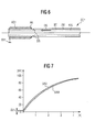
- Figure 6 shows an optical cable OC1 with an applied Guy spiral AS1, which with an earthing device ER1 is grounded.
- the optical cable OC1 has a plastic cable jacket AM on which a Kevlar layer KVL for improvement the mechanical tensile strength of the cable, which in turn is arranged around the cable core is.
- Figure 7 shows the tension curves along the Kevlar threads SKV and along the outer plastic cable sheath SAM in Dependence on the cable length of the optical cable OC1.
- the zero point of the path length is at the end of the guy spiral AS1, where an edge AK is formed.
- These breakdowns in the cable jacket preferably occur in the radial direction in the vicinity of the guy spiral or under the guy spiral AS1 on.
- Figures 6 and 7 serve only to explain the surface current OS and breakdown behavior of the optical cable OC1. There is no field control element in the optical cable OC1 according to FIG. 6 FE1 shown.
- Figure 8 shows the optical cable OC1 with field control element FE1 in AM cable sheath. That by means of the earthing device ER1 earthed guy spiral AS1 encloses the cable jacket AM in a portion of the optical cable, where , as explained in Figure 2, the guy spiral AS1 in the Plastic cable jacket AM presses in, so that there are reductions of the cable jacket circumference DE arise.
- the through the capacitive Coupling of the optical cable OC1 with the phase cables surface currents resulting from an overhead line now discharged capacitively into the field control element FE1 and can via the guy spiral AS1, which with the field controls FE1 can be in contact in an earthing device ER1 can be dissipated.
- the cable Protective cover BT with the optical fibers surrounded by FM filling material LW1 to LWn arranged.
- FIG. 9 shows a detail from FIG. 8 in detail.
- surface currents OS * along the cable surface lead to capacitive Flow IC through the outer layer of the cable jacket AM from the cable jacket surface to the field control element FE1 out. These form a current IFE in the field control element FE1.
- Figures 10 and 11 finally explain the principle of harmful dry band arcing, which is of the present invention is effectively prevented.
- Figure 10 is moisture FEU on the outside of the AM cable sheath so that leakage currents KS flow along the surface of the cable.
- These surface leakage currents KS are caused by voltages of the high voltage field induced on the surface of the optical cable.
- When drying the cable it is likely that certain Dry areas on the cable surface faster than others, so that dry zones arise between wet areas.
- Areas of FEU on the surface of the cable jacket AM, as shown in Figure 11 surface discharges OEN, which are associated with heat development, so that the Cable sheath is gradually destroyed. This mechanism too is effectively prevented by the present principle, since surface currents in the cable sheath or the one arranged there Field control element FE1 can be dissipated.
Landscapes
- Physics & Mathematics (AREA)
- General Physics & Mathematics (AREA)
- Optics & Photonics (AREA)
- Communication Cables (AREA)
- Light Guides In General And Applications Therefor (AREA)
Abstract
Description
- Elektrisch leitendes und mechanisch festes Anbringen der Mastbefestigung an einem Mast der Freileitungstrasse,
- Anbringen der Mastbefestigung am optischen Kabel,
- Eindrücken der Mastbefestigung in den Kabelmantel des optischen Kabels, so daß eine Vertiefung im eingedrückten Kabelmantel derart gebildet ist, daß der Abstand zwischen Feldsteuerelement und der Oberfläche des Kabelmantels verringert ist.
- Figur 1
- einen Querschnitt durch ein metallfreies, selbsttragendes optisches Kabel mit einem Feldsteuerelement und eine lose aufliegende Abspannspirale,
- Figur 2
- das optische Kabel gemäß Figur 1 nach Anbringen der Mastbefestigung,
- Figur 3
- die Anordnung des optischen Kabels in einer Hochspannungs-Freileitungsübertragungsstrecke,
- Figur 4
- ein Ausführungsbeispiel des optischen Kabels mit einem dreieckförmigen Feldsteuerelement,
- Figur 5
- ein Ausführungsbeispiel eines optischen Kabels mit einem gebogenen Feldsteuerelement,
- Figur 6
- einen Längsschnitt durch ein optisches Kabel mit einer Abspannspirale,
- Figur 7
- eine Spannungsverteilung entlang dem Kabelmantel,
- Figur 8
- einen detaillierten Längsschnitt durch ein optisches Kabel mit Abspannspirale gemäß Figur 6,
- Figur 9
- einen Ausschnitt aus Figur 8, und
- Figuren 10 und 12
- den Schädigungsmechanismus Dry-Band Arcing.
Claims (19)
- Metallfreies, selbsttragendes optisches Kabel (OC1) mit einer Kabelseele (KS) und einem darüber aufgebrachten, elektrisch isolierenden Kunststoff-Kabelmantel (AM) für die Verwendung als Luftkabel im Feldbereich von Phasenseilen (PS) einer Hochspannungsfreileitung (HF),
dadurch gekennzeichnet, daß
mindestens ein langgestrecktes Feldsteuerelement (FE1) im Inneren des Kabelmantels (AM) isoliert von dessen Oberfläche in derartigem Abstand von der Oberfläche (AD) vorgesehen ist, daß erst durch Eindrücken einer außen anzubringenden Mastbefestigung (AS1) in die Außenoberfläche des Kabelmantels (AM) oder erst durch Eindrücken einer außen anzubringenden Mastbefestigung (AS1) in die Außenoberfläche des Kabelmantels (AM) und Spannungsdurchschläge (SDU) im Betrieb eine Kontaktierung zwischen dem Feldsteuerelement (FE1) und der Mastbefestigung (AS1) bewirkt ist, wobei der zwischen dem Feldsteuerelement (FE1) und der Kabelseele (KS) liegende Mantelbereich und somit insgesamt eine ringsum geschlossene Kunststoff-Ummantelung um die Kabelseele (KS) bestehen bleibt. - Optisches Kabel nach Anspruch 1,
dadurch gekennzeichnet, daß
die Kabelseele (KS) ein zentral angeordnetes Kunststoffröhrchen (OH) aufweist, das mit mindestens einem Lichtwellenleiter (LW1 bis LWn) belegt ist. - Optisches Kabel nach Anspruch 2,
dadurch gekennzeichnet, daß
die Kabelseele (KS) außen rings um das Kunststoffröhrchen (OH) mindestens eine Lage zugfester Elemente (KVL) aufweist. - Optisches Übertragungselement nach einem der Ansprüche 1 bis 3,
dadurch gekennzeichnet, daß
die Mastbefestigung (AS1) durch eine Abspannspirale gebildet ist, die den Kabelmantel (AM) entlang einer vorgebbaren Teillänge schraubenförmig umfaßt. - Optisches Kabel nach einem der Ansprüche 1 bis 4,
dadurch gekennzeichnet, daß
die Mastbefestigung (AS1) geerdet ist. - Optisches Kabel nach einem der Ansprüche 1 bis 5,
dadurch gekennzeichnet, daß
sich das Feldsteuerelement (FE1) über die Gesamtlänge des Kabelmantels (AM) hinweg erstreckt. - Optisches Kabel nach einem der Ansprüche 1 bis 6,
dadurch gekennzeichnet, daß
für das Feldsteuerelement (FE1) ein elektrisch schwach leitendes Material gewählt ist. - Optisches Kabel nach einem der Ansprüche 1 bis 7,
dadurch gekennzeichnet, daß
das Feldsteuerelement (FE1) einen spezifischen elektrischen Widerstand von 1 kΩcm bis 1 MΩcm aufweist. - Optisches Kabel nach einem der Ansprüche 1 bis 8,
dadurch gekennzeichnet, daß
das Feldsteuerelement (FE1) in einer Kammer (KA1) im Kunststoffmaterial des Kabelmantels (AM) untergebracht ist. - Optisches Kabel nach Anspruch 9,
dadurch gekennzeichnet, daß
das Feldsteuerelement (FE1) die Kammer (KA1) vor dem Aufbringen der Mastbefestigung (KS1) lediglich teilweise ausfüllt, so daß mindestens ein Hohlraum (HR) frei bleibt. - Optisches Kabel nach einem der Ansprüche 9 oder 10,
dadurch gekennzeichnet, daß
die Kammer (KA1) mit dem Feldsteuerelement (FE1) in radialer Richtung bezogen auf die Zentralachse (ZA) der Kabelseele (KS) in der äußeren Schichthälfte des Kabelmantels (AM) vorgesehen ist. - Optisches Kabel nach einem der Ansprüche 9 bis 11,
dadurch gekennzeichnet, daß
sich das Feldsteuerelement (FE1) in der Kammer (KA1) radial nach innen hin am Rand der Kammer (KA1) abstützt. - Optisches Kabel nach einem der Ansprüche 1 bis 12,
dadurch gekennzeichnet, daß
das Feldsteuerelement (FE1) eine radial nach außen spitz zulaufende Querschnittsform aufweist. - Optisches Kabel nach einem der Ansprüche 1 bis 13,
dadurch gekennzeichnet, daß
das Feldsteuerelement (FE1) radial nach innen hin eine abgerundete Querschnittsform aufweist. - Optisches Kabel nach einem der Ansprüche 1 bis 14,
dadurch gekennzeichnet, daß
der zwischen dem Feldsteuerelement (FE1) und der Kabelseele (KS) liegende Mantelbereich (ID) des Kabelmantels (AM) eine derartige Schichtdicke aufweist, daß die Kabelseele (KS) auch bei zerstörter äußerer Mantelschicht weitgehend mechanisch oder elektrisch isolierend geschützt ist. - Optisches Kabel nach einem der Ansprüche 1 bis 15,
dadurch gekennzeichnet, daß
vor Anbringen der Mastbefestigung (AS1) am Kabelmantel (AM) der Abstand (AD) des Feldsteuerelemts (FE1) von der Oberfläche des Kabelmantels in einem Bereich von 0,1 mm bis 1 mm liegt. - Optisches Kabel nach einem der Ansprüche 1 bis 16,
dadurch gekennzeichnet, daß
der Abstand (ID) zwischen dem Feldsteuerelement (FE1) und der Kabelseele (KS) mindestens 1 mm beträgt. - Verfahren zur Montage eines optischen Kabels nach einem der Ansprüche 1 bis 17 in einer Hochspannungs-Freileitungstrasse mit folgenden Verfahrensschritten:Elektrisch leitendes und mechanisch festes Anbringen der Mastbefestigung (AS1) an einem Mast der Freileitungstrasse,Anbringen der Mastbefestigung (AS1) am optischen Kabel (OC1),Eindrücken der Mastbefestigung (AS1) in den Kabelmantel (AM) des optischen Kabels (OC1), so daß eine Vertiefung (DE) im eingedrückten Kabelmantel (AM*) derart gebildet ist, daß der Abstand (AD) zwischen Feldsteuerelement (FE1) und der Oberfläche des Kabelmantels (AM) verringert ist.
- Verfahren zur Montage eines optischen Kabels nach Anspruch 18,
dadurch gekennzeichnet, daß
die Mastbefestigung (AS1) derart in den Kabelmantel (AM) des optischen Kabels (OC1) eingedrückt wird, daß ein elektrischer Kontakt zwischen Feldsteuerelement (FE1) und Mastbefestigung (AS1) gebildet wird.
Applications Claiming Priority (2)
| Application Number | Priority Date | Filing Date | Title |
|---|---|---|---|
| DE10032247 | 2000-07-03 | ||
| DE2000132247 DE10032247A1 (de) | 2000-07-03 | 2000-07-03 | Metallfreies, selbsttragendes optisches Kabel und Verfahren zur Montage des optischen Kabels |
Publications (2)
| Publication Number | Publication Date |
|---|---|
| EP1170615A2 true EP1170615A2 (de) | 2002-01-09 |
| EP1170615A3 EP1170615A3 (de) | 2002-12-04 |
Family
ID=7647583
Family Applications (1)
| Application Number | Title | Priority Date | Filing Date |
|---|---|---|---|
| EP01116131A Withdrawn EP1170615A3 (de) | 2000-07-03 | 2001-07-03 | Metallfreies, selbsttragendes optisches Kabel und Verfahren zur Montage des optischen Kabels |
Country Status (2)
| Country | Link |
|---|---|
| EP (1) | EP1170615A3 (de) |
| DE (1) | DE10032247A1 (de) |
Cited By (1)
| Publication number | Priority date | Publication date | Assignee | Title |
|---|---|---|---|---|
| CN112558249A (zh) * | 2020-12-10 | 2021-03-26 | 安徽长荣光纤光缆科技有限公司 | 一种便于安装的管道光缆及其制备工艺 |
Family Cites Families (11)
| Publication number | Priority date | Publication date | Assignee | Title |
|---|---|---|---|---|
| US4342500A (en) * | 1979-08-10 | 1982-08-03 | Siemens Aktiengesellschaft | High voltage stabile optical cable structures |
| DE3504041A1 (de) * | 1984-06-29 | 1986-01-02 | Siemens AG, 1000 Berlin und 8000 München | Optisches kabel fuer hochspannungsfreileitungen |
| US4776665A (en) * | 1985-08-12 | 1988-10-11 | Siemens Aktiengesellschaft | Metal-free, self-bearing optical cable for high-tension overhead lines |
| DE3544085A1 (de) * | 1985-12-13 | 1987-06-19 | Kabelmetal Electro Gmbh | Elektrisches luftkabel mit lichtwellenleitern |
| DE3618659C2 (de) * | 1986-06-03 | 1997-04-10 | Rheydt Kabelwerk Ag | Metallfreies Luftkabel mit Lichtwellenleiteradern |
| FR2606560B1 (fr) * | 1986-11-06 | 1989-03-03 | Lienart Jean Pierre | Pince d'ancrage pour conducteur electrique isole equipe d'un cable porteur egalement isole |
| US5042904A (en) * | 1990-07-18 | 1991-08-27 | Comm/Scope, Inc. | Communications cable and method having a talk path in an enhanced cable jacket |
| US5325457A (en) * | 1991-09-20 | 1994-06-28 | Bottoms Jack Jr | Field protected self-supporting fiber optic cable |
| GB9325799D0 (en) * | 1993-12-17 | 1994-02-23 | Bicc Plc | Semiconductive linear element |
| IT1286009B1 (it) * | 1996-11-29 | 1998-06-26 | Pirelli Cavi E Sistemi Spa | Cavo ottico con nucleo tubolare metallico |
| GB2330705A (en) * | 1997-10-27 | 1999-04-28 | Pirelli General Plc | Limiting dry band arcing on an all-dielectric self-supporting cable; arc gap devices |
-
2000
- 2000-07-03 DE DE2000132247 patent/DE10032247A1/de not_active Withdrawn
-
2001
- 2001-07-03 EP EP01116131A patent/EP1170615A3/de not_active Withdrawn
Cited By (2)
| Publication number | Priority date | Publication date | Assignee | Title |
|---|---|---|---|---|
| CN112558249A (zh) * | 2020-12-10 | 2021-03-26 | 安徽长荣光纤光缆科技有限公司 | 一种便于安装的管道光缆及其制备工艺 |
| CN112558249B (zh) * | 2020-12-10 | 2022-06-14 | 安徽长荣光纤光缆科技有限公司 | 一种便于安装的管道光缆及其制备工艺 |
Also Published As
| Publication number | Publication date |
|---|---|
| DE10032247A1 (de) | 2002-01-17 |
| EP1170615A3 (de) | 2002-12-04 |
Similar Documents
| Publication | Publication Date | Title |
|---|---|---|
| DE69937112T2 (de) | Hybrides elektrisch-optisches kabel für freileitungsinstallationszwecke | |
| EP3639282B1 (de) | Steckbare hochspannungsdurchführung und elektrisches gerät mit steckbarer hochspannungsdurchführung | |
| DE2408512A1 (de) | Spleisstellen fuer hochspannungskabel und verfahren zu deren herstellung | |
| DE102013005901A1 (de) | Erdungskabel, insbesondere Bahnerdungskabel zur Erdung von Eisenbahneinrichtungen | |
| DE69736918T2 (de) | Zweischichtige elastische rohrförmige Umhüllung für elektrische Bauteile, insbesondere elektrische Kabelendverschlüsse, sowie dazugehöriges Herstellungsverfahren und Montage | |
| EP1490881B1 (de) | Dreileiterkabel | |
| CH709972A2 (de) | Elektrokabel. | |
| EP1558956B1 (de) | Hochspannungsbauteil mit optischer faser und verfahren zu seiner herstellung | |
| EP0457081B2 (de) | Isolator | |
| EP0029164A1 (de) | Hochspannungsdurchführung | |
| DE3618659C2 (de) | Metallfreies Luftkabel mit Lichtwellenleiteradern | |
| WO1996014683A1 (de) | Kapselung für einen gasisolierten hochspannungsleiter | |
| DE102011100983B4 (de) | Verbinderanordnung für Mittelspannungsanlagen | |
| DE10032247A1 (de) | Metallfreies, selbsttragendes optisches Kabel und Verfahren zur Montage des optischen Kabels | |
| DE69736916T2 (de) | Garnitur für Kabelendverschluss und Material für die Bildung der Garnitur | |
| DE2942925A1 (de) | Feuchtigkeitsgeschuetztes elektrisches kabel | |
| EP3631821A1 (de) | Steckbare hochspannungsdurchführung und elektrisches gerät mit der steckbaren hochspannungsdurchführung | |
| EP3074984B1 (de) | Hochspannungskabel | |
| EP0666576B1 (de) | Energiekabel | |
| EP2515313A1 (de) | Hochspannungsdurchführung | |
| DE102017102370A1 (de) | Verbindungsmuffe | |
| EP1783786A2 (de) | Kabelsystem mit magnetischer Schirmungshülle | |
| DE3506883A1 (de) | Metallfreies, in der nachbarschaft zu elektrischen hochspannungsanlagen verlegtes optisches luftkabel | |
| DE69808461T2 (de) | Von einer mit schirmen versehenen isolierhülse überdeckter kabelendverschluss | |
| EP3109867B1 (de) | Hochspannungsisolator |
Legal Events
| Date | Code | Title | Description |
|---|---|---|---|
| PUAI | Public reference made under article 153(3) epc to a published international application that has entered the european phase |
Free format text: ORIGINAL CODE: 0009012 |
|
| AK | Designated contracting states |
Kind code of ref document: A2 Designated state(s): AT BE CH CY DE DK ES FI FR GB GR IE IT LI LU MC NL PT SE TR |
|
| AX | Request for extension of the european patent |
Free format text: AL;LT;LV;MK;RO;SI |
|
| PUAL | Search report despatched |
Free format text: ORIGINAL CODE: 0009013 |
|
| AK | Designated contracting states |
Kind code of ref document: A3 Designated state(s): AT BE CH CY DE DK ES FI FR GB GR IE IT LI LU MC NL PT SE TR |
|
| AX | Request for extension of the european patent |
Free format text: AL;LT;LV;MK;RO;SI |
|
| AKX | Designation fees paid | ||
| REG | Reference to a national code |
Ref country code: DE Ref legal event code: 8566 |
|
| STAA | Information on the status of an ep patent application or granted ep patent |
Free format text: STATUS: THE APPLICATION IS DEEMED TO BE WITHDRAWN |
|
| 18D | Application deemed to be withdrawn |
Effective date: 20030422 |