EP1170552B1 - Device for distributing liquids - Google Patents
Device for distributing liquids Download PDFInfo
- Publication number
- EP1170552B1 EP1170552B1 EP01115543A EP01115543A EP1170552B1 EP 1170552 B1 EP1170552 B1 EP 1170552B1 EP 01115543 A EP01115543 A EP 01115543A EP 01115543 A EP01115543 A EP 01115543A EP 1170552 B1 EP1170552 B1 EP 1170552B1
- Authority
- EP
- European Patent Office
- Prior art keywords
- valve
- spindle
- shut
- handwheel
- drain
- Prior art date
- Legal status (The legal status is an assumption and is not a legal conclusion. Google has not performed a legal analysis and makes no representation as to the accuracy of the status listed.)
- Expired - Lifetime
Links
- 239000007788 liquid Substances 0.000 title claims description 4
- XLYOFNOQVPJJNP-UHFFFAOYSA-N water Substances O XLYOFNOQVPJJNP-UHFFFAOYSA-N 0.000 claims abstract description 15
- 238000007789 sealing Methods 0.000 claims description 9
- 238000010438 heat treatment Methods 0.000 claims description 6
- 238000009434 installation Methods 0.000 claims description 4
- 239000011796 hollow space material Substances 0.000 claims description 3
- 238000007599 discharging Methods 0.000 claims description 2
- 239000003651 drinking water Substances 0.000 claims description 2
- 235000020188 drinking water Nutrition 0.000 claims description 2
- 229920003023 plastic Polymers 0.000 claims description 2
- 239000004033 plastic Substances 0.000 claims description 2
- 239000000463 material Substances 0.000 claims 1
- 230000000717 retained effect Effects 0.000 claims 1
- 238000006073 displacement reaction Methods 0.000 description 3
- 238000009530 blood pressure measurement Methods 0.000 description 1
- 239000003638 chemical reducing agent Substances 0.000 description 1
- 230000001419 dependent effect Effects 0.000 description 1
- 238000011161 development Methods 0.000 description 1
- 230000018109 developmental process Effects 0.000 description 1
- 230000035622 drinking Effects 0.000 description 1
- 238000005516 engineering process Methods 0.000 description 1
- 230000002349 favourable effect Effects 0.000 description 1
- 230000003993 interaction Effects 0.000 description 1
- 238000009428 plumbing Methods 0.000 description 1
- 239000007787 solid Substances 0.000 description 1
- 230000008719 thickening Effects 0.000 description 1
Images


Classifications
-
- F—MECHANICAL ENGINEERING; LIGHTING; HEATING; WEAPONS; BLASTING
- F16—ENGINEERING ELEMENTS AND UNITS; GENERAL MEASURES FOR PRODUCING AND MAINTAINING EFFECTIVE FUNCTIONING OF MACHINES OR INSTALLATIONS; THERMAL INSULATION IN GENERAL
- F16L—PIPES; JOINTS OR FITTINGS FOR PIPES; SUPPORTS FOR PIPES, CABLES OR PROTECTIVE TUBING; MEANS FOR THERMAL INSULATION IN GENERAL
- F16L41/00—Branching pipes; Joining pipes to walls
- F16L41/02—Branch units, e.g. made in one piece, welded, riveted
- F16L41/03—Branch units, e.g. made in one piece, welded, riveted comprising junction pieces for four or more pipe members
-
- F—MECHANICAL ENGINEERING; LIGHTING; HEATING; WEAPONS; BLASTING
- F24—HEATING; RANGES; VENTILATING
- F24D—DOMESTIC- OR SPACE-HEATING SYSTEMS, e.g. CENTRAL HEATING SYSTEMS; DOMESTIC HOT-WATER SUPPLY SYSTEMS; ELEMENTS OR COMPONENTS THEREFOR
- F24D19/00—Details
- F24D19/10—Arrangement or mounting of control or safety devices
- F24D19/1006—Arrangement or mounting of control or safety devices for water heating systems
- F24D19/1009—Arrangement or mounting of control or safety devices for water heating systems for central heating
- F24D19/1015—Arrangement or mounting of control or safety devices for water heating systems for central heating using a valve or valves
-
- F—MECHANICAL ENGINEERING; LIGHTING; HEATING; WEAPONS; BLASTING
- F24—HEATING; RANGES; VENTILATING
- F24D—DOMESTIC- OR SPACE-HEATING SYSTEMS, e.g. CENTRAL HEATING SYSTEMS; DOMESTIC HOT-WATER SUPPLY SYSTEMS; ELEMENTS OR COMPONENTS THEREFOR
- F24D3/00—Hot-water central heating systems
- F24D3/10—Feed-line arrangements, e.g. providing for heat-accumulator tanks, expansion tanks ; Hydraulic components of a central heating system
- F24D3/1058—Feed-line arrangements, e.g. providing for heat-accumulator tanks, expansion tanks ; Hydraulic components of a central heating system disposition of pipes and pipe connections
- F24D3/1066—Distributors for heating liquids
Definitions
- the invention relates to a device for distributing liquids, in particular water, in drinking and service water systems, hot water heating systems or the like, with a manifold and at least one radially to the manifold arranged connection for a discharge line and with one of these axially parallel associated shut-off valve from a Valve base, which forms a guide for the operable by means of a handwheel valve spindle with the valve head and a valve upper part opposite this, on which the valve seat is formed.
- the invention has the object to find a more economical and above all space-saving option for the design of such a distribution station.
- the starting point of the invention is the idea that so far only in so-called heating circuit manifolds of heating systems followed principle, setting or To integrate control valves in the manifold, to apply even in a sanitary distributor. While it is expedient and therefore common in Schunikverteilern to mount the valves so that the required for operation hand wheels, actuators, servomotors or the like above the manifold (as in the generic publication EP 0 903 543 A2), it is at a distribution station in the sanitary area makes sense to arrange the shut-off valve for a branching off from the manifold pipe outlet line with this paraxial below the manifold; This also allows a small depth.
- a heating valve with presetting is known in single-hole mounting, which has a provided with an axial bore valve stem through which on the one hand carried a pressure measurement or by the other hand, the line can be emptied (DE 40 30 142 A1).
- a special emptying device is placed on the valve spindle for emptying the line to which a hollow space in the reaching into the emptying tube is held.
- an adjusting nut an axial displacement of the emptying tube which is movable within the hollow spindle is effected, which in turn causes an axial displacement of an emptying cone against a piston
- Valve ball loaded by a valve spring has the consequence and thus releases lateral emptying channels between the emptying cone and the emptying tube.
- the invention of a sanitary installation opens up the possibility to integrate the previously separately provided valve for emptying the outlet line in a simple manner in the shut-off valve.
- This has the further advantage in the configuration shown that the emptying valve and thus also the emptying opening are at the lowest point of the line, so that it can be completely emptied. Since the discharge of the liquid from the discharge line to be emptied also takes place downwards, the emptying can take place directly in a collecting tray arranged below the distributor.
- a particularly advantageous embodiment is that for actuating the shut-off valve required handwheel form of two parts, one of which, the inner part of the operation of the shut-off valve and the second, outer part of the Operation of the drain valve is used, so that special keys or tools are not required.
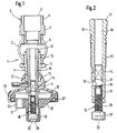
- Fig. 1 shows a longitudinal section through an embodiment of a device according to the invention, in which a shut-off valve 1 is integrated in a manifold with a manifold 2, of which a pipe socket 3 for the connection a branch line branches off.
- the shut-off valve 1 comprises two parts, a valve lower part 4 and an upper valve part 5, which face each other with respect to the distributor tube 2 axially parallel to the outlet line.
- the upper valve part 5 forms a valve seat 6 at the lower, screwed into the manifold 2 end of the pipe socket 3; it is provided in its overlying area outside with a nut contour 7 and has in the upper part of an external thread 8 for connection of the - not shown - outgoing line.
- the valve body 4 is screwed to the upper end of a pipe socket in the manifold 2; It is also provided with a nut contour 9 and serves as a guide for the valve stem 10 of the stop valve. 1
- the spindle 10 of the shut-off valve 1 has at its upper end a valve head 11 which cooperates to shut off the outgoing line to the valve seat 6 of the valve top 5; It has in the central region along its shank an external thread 12, by means of which it can be screwed within the valve body 4 provided with a corresponding internal thread and carries at its lower end to initiate the torque required for a handwheel 13.
- the handwheel 13 is rotatably mounted on the spindle 10 attached, which may be accomplished, for example, by a quadrangular configuration 14 of the central shaft portion of the spindle 10, and fixed relative to the spindle 10 by a locking screw.
- the spindle 10 of the shut-off valve 1 has an axial through hole 15, which serves for emptying the outlet line when the shut-off valve 1 is closed.
- an emptying valve 16 is inserted into the bore 15, the interaction with the shut-off valve 1 can be better explained with reference to FIG. 2, which shows the spindle 10 and the emptying valve 16 in a slightly larger scale.
- a valve seat is formed in the course of the axial bore 15 of the spindle 10 by a shoulder 17. against this valve seat acts Valve head 18 of the emptying valve 16, which is arranged at the upper end of a valve stem 19.
- the spindle 19 of the emptying valve 16 has along its shank an external thread 20, by means of which it is longitudinally adjustable along a corresponding internal thread in the lower region of the bore 15.
- a slot for attaching a screwdriver or, as shown, a recess 22 may have a polygonal cross-section, for example in the manner of a Allen screw.
- the handwheel 13 is, as can be seen again from Fig. 1, from an outer part 23, which causes the rotationally secure connection with the valve stem 10 and is widened as a solid part about bowl-shaped to a knurled ring 24 out. This results within this outer part 23, a cavity 25 which is closed to the outside by an inner lid portion 26.
- the cover part 26 is inserted into the knurled ring 24 so that it can be rotated relative to the outer part 23 about the valve axis; the connection can be secured by a snap ring 27.
- the two parts 23 and 26 of the handwheel are suitably made of plastic.
- the cover part 26 has, as FIG. 1 also reveals, a housing extension 28, which serves as protection and guidance for the head 21 of the spindle 19 of the emptying valve 16. Through an end-side opening 29, the recess 22 is accessible, for example, for applying a tool.
- the emptying valve 16 is closed, that is, the valve head 18, which may still be supported by an inserted into an annular O-ring on the valve seat 17; the shut-off valve 1 is opened, so that water can flow from the distributor pipe 2 into the outlet line. If the outlet line to be emptied, then the shut-off valve 1 is first closed and then the emptying valve 16 is opened. As a result, a transverse bore 30 arranged in the shaft of the spindle 10 below the valve seat 17 becomes 30 free, which opens into the cavity 25 of the handwheel 13, so that water can escape from the outlet line in this.
- at least one discharge opening 31 is provided in the cover part 26, which may be formed by a small cylindrical insert 32. Due to the rotatability of the cover part 26 relative to the outer part 23 of the handwheel 13, the emptying opening 31 can be pivoted on a circular ring in a favorable position for the water outlet.
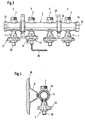
- Fig. 3 is a view of a distribution station is shown, which comprises on a manifold 2 a total of four inventively designed shut-off valves 1 at the positions A, B, C and D.
- the distributor tube 2 is provided at the left end in the illustration with an external thread 33 and at the opposite end with an outer flange 34 and a union nut 35.
- the distributor tube 2 can, as shown in FIG. 4 reveals, be secured by means of a pipe clamp 36 and a bracket 37 to a wall 38. From this representation, the small depth of the device according to the invention can be clearly seen.
- the manifold 2 is integrally formed, i. it comprises at the positions A, B, C and D a total of four shut-off valves 1.
- the entire device can also be modular, i. it can be provided any combinable distributor segments with one, two, three or four outlets.
- Fig. 3 is further indicated as the branch line was completed by the shut-off valve 1 in position B and, for example by means of an Allen wrench 39 which was running within the handwheel 13 emptying valve 16 is opened so that out of the emptying opening 31 water.
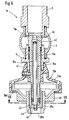
- FIG. 1 another embodiment of an inventive shut-off valve with integrated discharge option for the associated outgoing line is shown.
- a handwheel 13a is provided for actuating the shut-off valve 1 with the valve spindle 10a, which consists of an outer part 23a and an inner cover part 26a; the latter in turn has a housing projection 28a with an end opening 29a.
- the outer part 23a and the inner part 26a of the hand wheel 13a are rotatably connected to each other by engaging annular projections on the outer and inner edges, respectively.
- the spindle 19a of the emptying valve 16a consists of a valve rod 41 which has at its upper end the valve head 42 and the tensile and pressure-resistant at its lower end, but freely rotatably held in a foot 43.
- the spindle 10a of the shut-off valve 1a has the constriction 44, which cooperates with the valve head 42 of the emptying valve 16a, of the bore 15a on the valve head 11a, in such a way that the closure body 42 is aligned with the surface of the valve head 11 in the closed state of the emptying valve (FIG ).
- the foot 43 of the spindle 19a of the emptying valve 16a is approximately cup-shaped. He has polygonal, for example, hexagonal cross-section, and is rotatably, but longitudinally displaceably received in the hexagonal interior of the housing extension 28a.
- the foot 43 has an internal thread 45, with which it can be screwed onto a corresponding external thread at the lower end of the spindle 10a of the shut-off valve 1a and has in its bottom part an opening 46 which is penetrated by the valve rod 41.
- the valve rod 41 is tension and pressure resistant, for example, connected by a snap ring 47 inserted from the outside into an annular groove with the foot 43.
- FIG. 5 shows the shut-off valve 1a in the open position and the emptying valve 16a in the closed position
- FIG. 6 shows the shut-off valve 1a in the closed position and the emptying valve 16a in the open position.
- the overall nut-like foot 43 has in its lower region opposite each other side cutouts. Through these cutouts, opposite windows 49 are formed, through which the water flowing out of the outlet line can exit and flow out through the opening 29a in the housing projection 28a (FIG. 7).
- the exiting water jet is indicated in Fig. 8 at 50.
- valve head 11a of the shut-off valve 1a is provided at the rear with a thickening 52, which forms a sealing surface 53 inclined to the cylindrical outer surface of the valve spindle 19a.
- This oblique sealing surface 53 cooperates with a sealing edge 54, the at a step-like recess 55 is formed at the upper inner edge of the pipe socket 56, which forms the projecting into the manifold 2 part of the valve body 4 and on which the spindle guide is formed.
Landscapes
- Engineering & Computer Science (AREA)
- General Engineering & Computer Science (AREA)
- Mechanical Engineering (AREA)
- Chemical & Material Sciences (AREA)
- Thermal Sciences (AREA)
- Combustion & Propulsion (AREA)
- Physics & Mathematics (AREA)
- Devices For Dispensing Beverages (AREA)
- Multiple-Way Valves (AREA)
- Nozzles (AREA)
- Sanitary Device For Flush Toilet (AREA)
- Lift Valve (AREA)
- Mechanically-Actuated Valves (AREA)
Abstract
Description
Die Erfindung betrifft eine Vorrichtung zum Verteilen von Flüssigkeiten, insbesondere Wasser, bei Trink- und Brauchwasseranlagen, Warmwasser-Heizungsanlagen oder dergleichen, mit einem Verteilerrohr und mit mindestens einem radial zu dem Verteilerrohr angeordneten Anschluss für eine Abgangsleitung sowie mit einem dieser achsparallel zugeordneten Absperrventil aus einem Ventilunterteil, das eine Führung für die mittels eines Handrades betätigbare Ventilspindel mit dem Ventilkopf bildet und einem diesem gegenüberliegenden Ventiloberteil, an dem der Ventilsitz gebildet ist.The invention relates to a device for distributing liquids, in particular water, in drinking and service water systems, hot water heating systems or the like, with a manifold and at least one radially to the manifold arranged connection for a discharge line and with one of these axially parallel associated shut-off valve from a Valve base, which forms a guide for the operable by means of a handwheel valve spindle with the valve head and a valve upper part opposite this, on which the valve seat is formed.
Bei Sanitärinstallationen in der Gebäudetechnik befindet sich üblicherweise nach der Druckminder- und/oder Filtereinheit eine Verteilerstation, an der von einem Verteilerrohr die Leitungen zu den einzelnen Stockwerken bzw. Verbrauchern des Gebäudes abzweigen. Da Trinkwasserleitungen üblicherweise im Keller in die Gebäude hineingeführt werden, erstrecken sich die Abgangsleitungen von dem Verteilerrohr regelmäßig nach oben.In plumbing installations in building technology is usually located after the pressure reducer and / or filter unit, a distribution station at the branch off from a manifold, the lines to the individual floors or consumers of the building. As drinking water pipes are usually led into the building in the basement, the outlet pipes from the distribution pipe regularly extend upwards.
Diese Verteilerrohre sind meist Rohrabschnitte mit angesetzten Rohrstutzen, auf die übliche Ventile, meist Schrägventile, aufgeschraubt werden. Im Bereich einer solchen Verteilerstation wird jeder Abgangsleitung ein Absperrventil zugeordnet; außerdem muss ein Entleerventil vorgesehen sein, um die betreffende Abgangsleitung in geschlossenem Zustand des Absperrventils entleeren zu können. Abgesehen vom Aufwand für die Installation solcher Verteilerstationen ist in der Regel auch der Platzbedarf für solche Schrägventile sehr groß.These distribution pipes are usually pipe sections with attached pipe socket, to the usual valves, mostly inclined valves, are screwed. In the area of such a distribution station each outlet line is assigned a shut-off valve; In addition, an emptying valve must be provided in order to be able to empty the relevant outlet line in the closed state of the shut-off valve. Apart from the expense of installing such distribution stations, the space required for such slanted valves is usually very large.
Vor diesem Hintergrund liegt der Erfindung die Aufgabe zugrunde, eine wirtschaftlichere und vor allem platzsparendere Möglichkeit für die Gestaltung einer derartigen Verteilerstation zu finden.Against this background, the invention has the object to find a more economical and above all space-saving option for the design of such a distribution station.
Gemäß der Erfindung wird diese Aufgabe durch eine Vorrichtung mit den Merkmalen des unabhängigen Anspruchs 1 gelöst.According to the invention, this object is achieved by a device having the features of
Vorteilhafte Weiterbildungen ergeben sich aus den abhängigen Ansprüchen.Advantageous developments emerge from the dependent claims.
Ausgangsbasis der Erfindung ist der Gedanke, das bislang nur bei sogenannten Heizkreisverteilern von Heizungsanlagen befolgte Prinzip, Einstell- bzw.
Regelventile in das Verteilerrohr zu integrieren, auch bei einem Sanitärverteiler anzuwenden. Während es bei Heizkreisverteilern zweckmäßig und daher üblich ist, die Ventile so zu montieren, dass die zur Betätigung erforderlichen Handräder, Stellantriebe, Stellmotoren oder dergleichen oberhalb des Verteilerrohrs liegen (wie in der gattungsbildenden Veröffentlichung EP 0 903 543 A2), ist es bei einer Verteilerstation im Sanitärbereich sinnvoll, das Absperrventil für eine vom Verteilerrohr nach oben abzweigende Abgangsleitung mit dieser achsparallel unterhalb des Verteilerrohres anzuordnen; dies ermöglicht auch eine geringe Bautiefe.The starting point of the invention is the idea that so far only in so-called heating circuit manifolds of heating systems followed principle, setting or
To integrate control valves in the manifold, to apply even in a sanitary distributor. While it is expedient and therefore common in Heizkreisverteilern to mount the valves so that the required for operation hand wheels, actuators, servomotors or the like above the manifold (as in the generic publication EP 0 903 543 A2), it is at a distribution station in the sanitary area makes sense to arrange the shut-off valve for a branching off from the manifold pipe outlet line with this paraxial below the manifold; This also allows a small depth.
Ebenfalls bei Heizungsanlagen ist ein Heizungsventil mit Voreinstellung in Einlochbefestigung bekannt geworden, das eine mit einer axialen Bohrung versehene Ventilspindel besitzt, durch die einerseits eine Druckmessung erfolgen bzw. durch die andererseits auch die Leitung entleert werden kann (DE 40 30 142 A1). Bei diesem Ventil wird zum Entleeren der Leitung auf die Ventilspindel eine besondere Entleervorrichtung aufgesetzt, an der ein in die Hohlspindel hineinreichendes Entleerrohr gehalten ist. Mittels einer Verstellmutter wird eine Axialverschiebung des innerhalb der Hohlspindel beweglichen Entleerrohres bewirkt, die ihrerseits eine Axialverschiebung eines Entleerkegels gegen eine durch eine Ventilfeder belastete Ventilkugel zur Folge hat und so zwischen Entleerkegel und Entleerrohr seitliche Entleerkanäle freigibt.Also in heating systems, a heating valve with presetting is known in single-hole mounting, which has a provided with an axial bore valve stem through which on the one hand carried a pressure measurement or by the other hand, the line can be emptied (DE 40 30 142 A1). In this valve, a special emptying device is placed on the valve spindle for emptying the line to which a hollow space in the reaching into the emptying tube is held. By means of an adjusting nut, an axial displacement of the emptying tube which is movable within the hollow spindle is effected, which in turn causes an axial displacement of an emptying cone against a piston Valve ball loaded by a valve spring has the consequence and thus releases lateral emptying channels between the emptying cone and the emptying tube.
Vor diesem Hintergrund eröffnet die Erfindung bei einer Sanitärinstallation die Möglichkeit, das bisher gesondert vorzusehende Ventil für die Entleerung der Abgangsleitung auf einfache Weise in das Absperrventil zu integrieren. Dies hat bei der gezeigten Konfiguration noch den weiteren Vorteil, dass das Entleerventil und damit auch die Entleeröffnung am tiefsten Punkt der Leitung liegen, so dass diese vollständig entleert werden kann. Da der Austritt der Flüssigkeit aus der zu entleerenden Abgangsleitung ebenfalls nach unten erfolgt, kann die Entleerung unmittelbar in eine unterhalb des Verteilers angeordnete Auffangschale erfolgen.Against this background, the invention of a sanitary installation opens up the possibility to integrate the previously separately provided valve for emptying the outlet line in a simple manner in the shut-off valve. This has the further advantage in the configuration shown that the emptying valve and thus also the emptying opening are at the lowest point of the line, so that it can be completely emptied. Since the discharge of the liquid from the discharge line to be emptied also takes place downwards, the emptying can take place directly in a collecting tray arranged below the distributor.
Eine besonders vorteilhafte Ausführung besteht darin, dass zur Betätigung des Absperrventils erforderliche Handrad aus zwei Teilen auszubilden, von denen der eine, innere Teil der Betätigung des Absperrventils und der zweite, äußere Teil der Betätigung des Entleerventils dient, so dass besondere Schlüssel oder Werkzeuge nicht erforderlich sind.A particularly advantageous embodiment is that for actuating the shut-off valve required handwheel form of two parts, one of which, the inner part of the operation of the shut-off valve and the second, outer part of the Operation of the drain valve is used, so that special keys or tools are not required.
Weitere Merkmale und vorteilhafte Eigenschaften der Erfindung ergeben sich aus der nachstehenden Beschreibung der in der Zeichnung dargestellten Ausführungsbeispiele. Es zeigt
- Fig. 1
- einen Schnitt durch eine erfindungsgemäße Verteilervorrichtung mit einem Absperrventil,
- Fig. 2
- einen Längsschnitt durch die Ventilspindel gemäß Fig. 1 in größerem Maßstab,
- Fig. 3
- eine Ansicht einer Verteilerstation mit mehreren Absperrventilen,
- Fig. 4
- einen Querschnitt entlang der Linie IV-IV in Fig. 3, die
- Fig. 5 und 6 der Fig. 1
- entsprechende Darstellungen einer anderen Ausführungsform in unterschiedlichen Betriebszuständen,
- Fig. 7
- einen Querschnitt entlang der Linie VII-VII in Fig. 6,
- Fig. 8
- eine Ansicht des Absperrventils gemäß Fig. 6 in Entleerstellung und
- Fig. 9
- eine stark vergrößerte Darstellung des Ventilkopfes des Absperrventils gemäß Detail X in Fig. 5.
- Fig. 1
- a section through a distributor device according to the invention with a shut-off valve,
- Fig. 2
- a longitudinal section through the valve spindle of FIG. 1 on a larger scale,
- Fig. 3
- a view of a distribution station with several shut-off valves,
- Fig. 4
- a cross-section along the line IV-IV in Fig. 3, the
- FIGS. 5 and 6 of FIG. 1
- corresponding representations of another embodiment in different operating states,
- Fig. 7
- a cross section along the line VII-VII in Fig. 6,
- Fig. 8
- a view of the shut-off valve of FIG. 6 in emptying and
- Fig. 9
- a greatly enlarged view of the valve head of the shut-off valve according to detail X in Fig. 5th
Fig. 1 zeigt einen Längsschnitt durch eine Ausführungsform einer erfindungsgemäßen Vorrichtung, bei der ein Absperrventil 1 in einen Verteiler mit einem Verteilerrohr 2 integriert ist, von dem ein Rohrstutzen 3 für den Anschluss einer Abgangsleitung abzweigt. Demgemäß umfasst das Absperrventil 1 zwei Teile, ein Ventilunterteil 4 und ein Ventiloberteil 5, die sich bezüglich des Verteilerrohres 2 achsparallel zur Abgangsleitung gegenüberliegen.Fig. 1 shows a longitudinal section through an embodiment of a device according to the invention, in which a shut-off
Das Ventiloberteil 5 bildet an dem unteren, in das Verteilerrohr 2 eingeschraubten Ende des Rohrstutzens 3 einen Ventilsitz 6; es ist in seinem darüberliegenden Bereich außen mit einer Mutternkontur 7 versehen und besitzt im oberen Bereich ein Außengewinde 8 zum Anschluss der - nicht dargestellten - Abgangsleitung. Das Ventilunterteil 4 ist mit dem oberen Ende eines Rohrstutzens in das Verteilerrohr 2 eingeschraubt; es ist ebenfalls mit einer Mutternkontur 9 versehen und dient als Führung für die Ventilspindel 10 des Absperrventils 1.The upper valve part 5 forms a
Die Spindel 10 des Absperrventils 1 besitzt an ihrem oberen Ende einen Ventilkopf 11, der zum Absperren der Abgangsleitung mit dem Ventilsitz 6 des Ventiloberteils 5 zusammenwirkt; sie besitzt im mittleren Bereich entlang ihres Schaftes ein Außengewinde 12, mittels dessen sie innerhalb des mit einem entsprechenden Innengewinde ausgestatteten Ventilunterteils 4 schraubbar ist und trägt an ihrem unteren Ende zur Einleitung des dafür erforderlichen Drehmoments ein Handrad 13. Das Handrad 13 ist drehfest auf die Spindel 10 aufgesteckt, was beispielsweise durch eine vierkantige Ausgestaltung 14 des mittleren Schaftteils der Spindel 10 bewerkstelligt sein kann, und gegenüber der Spindel 10 durch eine Feststellschraube fixiert.The
Erfindungsgemäß besitzt die Spindel 10 des Absperrventils 1 eine axiale durchgehende Bohrung 15, die bei geschlossenem Absperrventil 1 zum Entleeren der Abgangsleitung dient. Zum Verschließen und Öffnen dieser Entleerleitung ist in die Bohrung 15 ein Entleerventil 16 eingesetzt, dessen Zusammenwirken mit dem Absperrventil 1 anhand Fig. 2 besser erläutert werden kann, welche die Spindel 10 und das Entleerventil 16 in etwas größerem Maßstab zeigt.According to the invention, the
Für das Entleerventil 16 ist im Verlauf der axialen Bohrung 15 der Spindel 10 durch eine Schulter 17 ein Ventilsitz gebildet. Gegen diesen Ventilsitz wirkt der Ventilkopf 18 des Entleerventils 16, der am oberen Ende einer Ventilspindel 19 angeordnet ist. Auch die Spindel 19 des Entleerventils 16 weist entlang ihres Schaftes ein Außengewinde 20 auf, mittels dessen sie entlang eines entsprechenden Innengewindes im unteren Bereich der Bohrung 15 längsverstellbar ist. Zur Einleitung der dazu erforderlichen Drehbewegung besitzt die Spindel 19 am unteren Ende einen Fuß 21, der stirnseitig einen Schlitz zum Ansetzen eines Schraubendrehers oder, wie dargestellt, eine Vertiefung 22 mit polygonalem Querschnitt zum Beispiel nach Art einer Inbusschraube aufweisen kann.For the emptying
Das Handrad 13 besteht, wie wiederum Fig. 1 erkennen lässt, aus einem äußeren Teil 23, das die verdrehsichere Verbindung mit der Ventilspindel 10 bewirkt und als Massivteil etwa schüsselförmig zu einem Rändelring 24 hin aufgeweitet ist. Dadurch entsteht innerhalb dieses äußeren Teils 23 ein Hohlraum 25, der nach außen hin durch ein inneres Deckelteil 26 abgeschlossen ist. Das Deckelteil 26 ist in den Rändelring 24 so eingesetzt, dass es gegenüber dem äußeren Teil 23 um die Ventilachse gedreht werden kann; die Verbindung kann durch einen Sprengring 27 gesichert sein. Die beiden Teile 23 und 26 des Handrades bestehen zweckmäßig aus Kunststoff.The
Das Deckelteil 26 besitzt, wie Fig. 1 weiterhin erkennen lässt, einen Gehäuseansatz 28, der als Schutz und Führung für den Kopf 21 der Spindel 19 des Entleerventils 16 dient. Durch eine stirnseitige Durchbrechung 29 ist die Vertiefung 22 zugänglich, zum Beispiel zum Ansetzen eines Werkzeuges.The
Im Betriebszustand der Vorrichtung ist das Entleerventil 16 geschlossen, d.h. liegt der Ventilkopf 18, der noch durch einen in eine Ringnut eingelegten O-Ring unterstützt sein kann, an dem Ventilsitz 17 an; das Absperrventil 1 ist geöffnet, so dass Wasser aus dem Verteilerrohr 2 in die Abgangsleitung strömen kann. Soll die Abgangsleitung entleert werden, dann wird zunächst das Absperrventil 1 geschlossen und danach das Entleerventil 16 geöffnet. Dadurch wird eine im Schaft der Spindel 10 unterhalb des Ventilsitzes 17 angeordnete Querbohrung 30 frei, die in den Hohlraum 25 des Handrades 13 mündet, so dass Wasser aus der Abgangsleitung in diesen austreten kann. Zur Ausleitung des auf diese Weise austretenden Wassers ist im Deckelteil 26 mindestens eine Entleeröffnung 31 vorgesehen, die durch einen kleinen zylindrischen Einsatz 32 gebildet sein kann. Durch die Verdrehbarkeit des Deckelteils 26 gegenüber dem äußeren Teil 23 des Handrades 13 kann die Entleeröffnung 31 auf einem Kreisring in eine für den Wasseraustritt günstige Position verschwenkt werden.In the operating state of the device, the emptying
In Fig. 3 ist eine Ansicht einer Verteilerstation dargestellt, die an einem Verteilerrohr 2 insgesamt vier erfindungsgemäß ausgebildete Absperrventile 1 an den Positionen A, B, C und D umfasst. Das Verteilerrohr 2 ist an dem in der Darstellung linken Ende mit einem Außengewinde 33 und an dem gegenüberliegenden Ende mit einer Außenbördelung 34 und einer Überwurfmutter 35 versehen. Das Verteilerrohr 2 kann, wie Fig. 4 erkennen lässt, mittels einer Rohrschelle 36 und eines Bügels 37 an einer Wand 38 befestigt werden. Aus dieser Darstellung ist deutlich die geringe Bautiefe der erfindungsgemäßen Vorrichtung erkennbar.In Fig. 3 is a view of a distribution station is shown, which comprises on a manifold 2 a total of four inventively designed shut-off
Bei der in Fig. 3 dargestellten Verteilerstation ist das Verteilerrohr 2 einteilig ausgebildet, d.h. es umfasst an den Positionen A, B, C und D insgesamt vier Absperrventile 1. Die gesamte Vorrichtung kann aber auch modular aufgebaut sein, d.h. es können beliebig kombinierbare Verteilersegmente mit einem, zwei, drei oder vier Abgängen vorgesehen sein.In the distribution station shown in Fig. 3, the
In Fig. 3 ist weiterhin angedeutet, wie durch das Absperrventil 1 in der Position B die Zweigleitung abgeschlossen wurde und wie zum Beispiel mittels eines Inbusschlüssels 39 das innerhalb des Handrades 13 verlaufende Entleerventil 16 geöffnet wurde, so dass aus der Entleeröffnung 31 Wasser heraustritt.In Fig. 3 is further indicated as the branch line was completed by the shut-off
In den Fig. 5 bis 8 ist eine andere Ausführungsform für ein erfindungsgemäßes Absperrventil mit integrierter Entleermöglichkeit für die zugeordnete Abgangsleitung dargestellt. Im Prinzip entspricht die Anordnung des Absperrventils 1 a demjenigen gemäß Fig. 1, jedenfalls was Ausgestaltung und Anordnung des Verteilerrohrs 2, des Ventilunterteils 4 und des Ventiloberteils 5 anlangt. Auch hier ist zur Betätigung des Absperrventils 1 mit der Ventilspindel 10a ein Handrad 13a vorgesehen, das aus einem äußeren Teil 23a und einem inneren Deckelteil 26a besteht; letzteres besitzt wiederum einen Gehäuseansatz 28a mit einer stirnseitigen Durchbrechung 29a. Das äußere Teil 23a und das innere Teil 26a des Handrades 13a sind durch Einrasten ringförmiger Vorsprünge an den äußeren bzw. inneren Rändern gegeneinander verdrehbar miteinander verbunden.5 to 8, another embodiment of an inventive shut-off valve with integrated discharge option for the associated outgoing line is shown. In principle, the arrangement of the Shut-off
Bei dieser Ausführungsform besteht die Spindel 19a des Entleerventils 16a aus einer Ventilstange 41, die an ihrem oberen Ende den Ventilkopf 42 aufweist und die an ihrem unteren Ende zug- und druckfest, aber frei drehbar in einem Fuß 43 gehalten ist. Die Spindel 10a des Absperrventils 1a weist die mit dem Ventilkopf 42 des Entleerventils 16a zusammenwirkende Verengung 44 der Bohrung 15a am Ventilkopf 11a auf, und zwar so, dass der Verschlusskörper 42 in geschlossenem Zustand des Entleerventils mit der Oberfläche des Ventilkopfes 11 fluchtet (Fig. 5).In this embodiment, the
Der Fuß 43 der Spindel 19a des Entleerventils 16a ist etwa becherartig ausgebildet. Er hat polygonförmigen, zum Beispiel sechseckigen Querschnitt, und ist so in dem ebenfalls sechseckigen Innenraum des Gehäuseansatzes 28a drehfest, aber längsverschieblich aufgenommen. Der Fuß 43 besitzt ein Innengewinde 45, mit dem er auf ein entsprechendes Außengewinde am unteren Ende der Spindel 10a des Absperrventils 1a aufschraubbar ist und weist in seinem Bodenteil eine Durchbrechung 46 auf, die von der Ventilstange 41 durchsetzt wird. Die Ventilstange 41 ist zug- und druckfest, zum Beispiel durch einen von außen in eine Ringnut eingesetzten Sprengring 47 mit dem Fuß 43 verbunden.The
Fig. 5 zeigt das Absperrventil 1a in geöffneter und das Entleerventil 16a in geschlossener Stellung, Fig. 6 das Absperrventil 1a in geschlossener und das Entleerventil 16a in geöffneter Stellung.5 shows the shut-off
Während die Betätigung der Spindel 10a des Absperrventils 1a durch das äußere Teil 23a des Handrades 13a erfolgt, das mit der Spindel 10a drehfest verbunden ist, kann bei dieser Ausführungsform die Betätigung der Spindel 19a des Entleerventils 16a durch das innere Deckelteil 26a des Handrades 13a erfolgen, das über den in dem Gehäuseansatz 28a drehfest, aber längsverschieblich gehaltenen Fuß 43 und die Gewindeverbindung 45 eine Längsbewegung der Ventilstange 41 ermöglicht. Zur Verdrehung des Deckelteils 26a gegenüber dem äußeren Teil 23a ist es mit Flügeln 48 versehen, die vor allem in der Ansicht der Fig. 8 deutlich zu erkennen sind.While the actuation of the
Der insgesamt mutternartig ausgebildete Fuß 43 besitzt in seinem unteren Bereich einander gegenüberliegend seitliche Ausfräsungen. Durch diese Ausfräsungen werden einander gegenüberliegende Fenster 49 gebildet, durch die das aus der Abgangsleitung ausfließende Wasser austreten und durch die Durchbrechung 29a im Gehäuseansatz 28a abfließen kann (Fig. 7). Der austretende Wasserstrahl ist in Fig. 8 bei 50 angedeutet.The overall nut-
Eine vergrößerte Darstellung der Dichtungen zwischen dem Kopf 42 der Ventilstange 41 und dem Ventilkopf 11a einerseits sowie zwischen diesem und dem in das Verteilerrohr 2 hineinragenden Rohrstutzen andererseits zeigt Fig. 9 als Detail X in Fig. 5. Der für die Längsverschiebung der Ventilspindel 10a des Absperrventils 1a erforderliche Spalt zwischen der Außenfläche der Ventilspindel 10a und der Spindelführung am Ventilunterteil 4 kann in an sich bekannter Weise durch Dichtringe 51 gedichtet werden. Da das Absperrventil 1a aber während der längsten Zeit des Betriebes der Verteilervorrichtung geöffnet sein wird, d.h. von Wasser beaufschlagt ist, ist es sinnvoll, im oberen Bereich dieses Spaltes eine zusätzliche Dichtung vorzusehen.An enlarged view of the seals between the
Wie insbesondere Fig. 9 erkennen lässt, ist der Ventilkopf 11a des Absperrventils 1a rückseitig mit einer Verdickung 52 versehen, die eine zur zylindrischen Außenfläche der Ventilspindel 19a geneigt verlaufende Dichtfläche 53 bildet. Diese schräge Dichtfläche 53 wirkt mit einer Dichtkante 54 zusammen, die an einer treppenartigen Ausnehmung 55 am oberen Innenrand des Rohrstutzens 56 gebildet ist, der den in das Verteilerrohr 2 hineinragenden Teil des Ventilunterteils 4 bildet und an dem die Spindelführung ausgebildet ist. Durch diese metallische Dichtung wird der Spalt zwischen der Spindel 10a und der Spindelführung im Rohrstutzen 56 am oberen Ende abgedichtet; dadurch kann vermieden werden, dass sich in dem Spalt Wasserstein bildet und die Gefahr besteht, dass die Spindel mit der Zeit schwergängig wird oder gar festsitzt.As can be seen in particular from FIG. 9, the
Claims (22)
- An apparatus for distributing liquids, in particular water, in drinking water and service water installations, hot-water heating installations or the like, having a distributor pipe (2) and having at least one connector (3) arranged radially to the distributor pipe (2) for a discharge duct and also having an associated shut-off valve (1,1a) axially parallel thereto, wherein the shut-off valve (1,1a) comprises a valve lower part (4,4a) which has a valve head (11,11a) and which forms a guide for the valve spindle (10,10a) which can be actuated by a handwheel (13,13a), and comprises a valve upper part (5,5a) which is situated opposite the latter with respect to the distributor pipe (2) and on which the valve seat (6) is formed,
characterised by the following features:- the valve spindle (10,10a) of the shut-off valve (1,1a) has an axial bore (15,15a) which forms a drain duct for the discharge duct and, in turn, can be closed by a drain valve (16,16a),- the axial bore (15,15a) is continuous over the length of the spindle (10,10a) and the drain valve (16,16a) is arranged concentrically to the latter with an axially parallel movement direction, and- the drain valve (16,16a) comprises, in turn, a valve spindle (19,19a) which, at one end, is provided with a valve head (18,42) which acts against a valve seat formed in the course of the bore (15,15a) by a constriction (17,44) and which, at the other end, is provided with means for actuating the valve. - An apparatus according to Claim 1, characterised in that the constriction (44) is disposed on the valve head (11a) of the shut-off valve (1a).
- An apparatus according to Claim 1 or 2, characterised in that the valve spindle (19) of the drain valve (16) is provided at least over part of its length with an external screw-thread (20) and the bore (15) is provided with a corresponding internal screw-thread.
- An apparatus according to any one of Claims 1 to 3, characterised in that the valve spindle (19) of the drain valve (16) is provided at its end opposite the valve head (18) with a base (21) which has a profile suitable for the application of a torque.
- An apparatus according to any one of Claims 1 to 4, characterised in that the handwheel (13,13a) comprises an outer operating part (23,23a) which can be connected to the spindle (10,10a) of the shut-off valve (1,1a) in a manner precluding relative rotation and which has a grip rim, and also comprises an inner cover part (26,26a).
- An apparatus according to Claim 5, characterised in that the outer part (23,23a) is widened in a dish-shaped manner and the inner part (26,26a) is designed so as to close in the manner of a cover the hollow space (25) thus formed.
- An apparatus according to Claim 6, characterised in that the inner part (26,26a) is rotatable about the valve axis relative to the outer part (23,23a).
- An apparatus according to any one of Claims 3 to 7, characterised in that the spindle (10) of the shut-off valve (1) has below the constriction (17) of the drain valve (16) at least one radial bore (30) as a drain opening discharging into the hollow space (25) of the handwheel (13), and in that the handwheel (13) has at least one outlet opening (31).
- An apparatus according to Claim 8, characterised in that the at least one outlet opening (31) is provided in the inner part (26) of the handwheel (13).
- An apparatus according to any one of Claims 5 to 9, characterised in that the inner part (26,26a) of the handwheel (13,13a) has a housing extension (28,28a) to accommodate the base (21,43) of the spindle (19,19a) of the drain valve (16,16a).
- An apparatus according to Claim 10, characterised in that the housing extension (28,28a) has an opening (29,29a) at the end face.
- An apparatus according to Claim 10 or 11, characterised in that the housing extension (28a) encloses in a manner precluding relative rotation but axially displaceably the base (43) of the spindle (19a) of the drain valve (16a).
- An apparatus according to any one of Claims 5 to 12, characterised in that the outer part (26a) of the handwheel (13a) is provided with wing-like projections (48) for the application of a rotating movement to actuate the drain valve (16a).
- An apparatus according to any one of Claims 1 to 13, characterised in that the spindle (19a) of the drain-valve (16a) comprises a valve stem (41) which at the upper end is provided with the valve head (42) and the lower end of which is retained rotatably in a base part (43).
- An apparatus according to Claim 14, characterised in that the base part (43) is sleeve-shaped and can be screwed on to the lower end of the spindle (10a) of the shut-off valve (1a) .
- An apparatus according to Claim 14 or 15, characterised in that the base part (43) has openings (49) forming outlet orifices.
- An apparatus according to any one of Claims 1 to 16, characterised in that the outer part (23,23a) of the handwheel (13,13a) can be connected by means of a radial clamping screw to the spindle (10,10a) of the shut-off valve (1,1a).
- An apparatus according to any one of Claims 1 to 17, characterised in that the handwheel (13,13a) consists of plastics material.
- An apparatus according to any one of Claims 1 to 18, characterised in that the valve head (11,11a) of the shut-off valve (1,1a) has on its outside a sealing face (53) which in the open position of the shut-off valve (1,1a) cooperates with a sealing edge (54) disposed on the valve lower part (4).
- An apparatus according to Claim 19, characterised in that the sealing face (53) is formed on a thickened portion (52) of the valve head (11,11a).
- An apparatus according to Claim 20, characterised in that the sealing face (53) extends flat and inclined relative to the cylindrical outer surface of the valve head (11,11a).
- An apparatus according to any one of Claims 19 to 21, characterised in that the sealing edge (54) is formed on a stepped recess (55) on the upper inner rim of the valve lower part (4).
Applications Claiming Priority (4)
| Application Number | Priority Date | Filing Date | Title |
|---|---|---|---|
| DE20011693U | 2000-07-05 | ||
| DE20011693 | 2000-07-05 | ||
| DE20014320U DE20014320U1 (en) | 2000-07-05 | 2000-08-19 | Device for distributing liquids, especially water, in drinking and industrial water systems, hot water heating systems or the like. |
| DE20014320U | 2000-08-19 |
Publications (3)
| Publication Number | Publication Date |
|---|---|
| EP1170552A2 EP1170552A2 (en) | 2002-01-09 |
| EP1170552A3 EP1170552A3 (en) | 2003-06-04 |
| EP1170552B1 true EP1170552B1 (en) | 2006-07-26 |
Family
ID=26056374
Family Applications (1)
| Application Number | Title | Priority Date | Filing Date |
|---|---|---|---|
| EP01115543A Expired - Lifetime EP1170552B1 (en) | 2000-07-05 | 2001-06-28 | Device for distributing liquids |
Country Status (3)
| Country | Link |
|---|---|
| EP (1) | EP1170552B1 (en) |
| AT (1) | ATE334349T1 (en) |
| DE (1) | DE50110525D1 (en) |
Families Citing this family (2)
| Publication number | Priority date | Publication date | Assignee | Title |
|---|---|---|---|---|
| DE202007014858U1 (en) * | 2007-10-19 | 2008-01-03 | Kermi Gmbh | test set |
| SI3728956T1 (en) * | 2017-12-20 | 2024-05-31 | R.B.M. S.P.A. | Collector for distributing a heat transfer fluid in a heating and/or cooling and/or conditioning network, in particular of household and/or industrial type |
Family Cites Families (4)
| Publication number | Priority date | Publication date | Assignee | Title |
|---|---|---|---|---|
| DE4030142A1 (en) * | 1990-09-24 | 1992-03-26 | Neheim Goeke & Co Metall | Heating valve with independent preadjustment - has valve closure member fixed on one side in hollow valve spindle |
| DE19652117C1 (en) * | 1996-12-14 | 1998-04-16 | Heimeier Gmbh Metall Theodor | Adaptor fitting for radiator valves |
| DE29704960U1 (en) * | 1997-03-18 | 1998-04-16 | Reich Kg Regel & Sicherheits | Adjusting device |
| DE29716779U1 (en) * | 1997-09-18 | 1999-01-28 | Dumser Metallbau GmbH & Co. KG, 76829 Landau | Distributor for a circuit of a heating or cooling supply system operated with a liquid medium |
-
2001
- 2001-06-28 DE DE50110525T patent/DE50110525D1/en not_active Expired - Fee Related
- 2001-06-28 EP EP01115543A patent/EP1170552B1/en not_active Expired - Lifetime
- 2001-06-28 AT AT01115543T patent/ATE334349T1/en not_active IP Right Cessation
Also Published As
| Publication number | Publication date |
|---|---|
| EP1170552A3 (en) | 2003-06-04 |
| DE50110525D1 (en) | 2006-09-07 |
| ATE334349T1 (en) | 2006-08-15 |
| EP1170552A2 (en) | 2002-01-09 |
Similar Documents
| Publication | Publication Date | Title |
|---|---|---|
| EP2573283B1 (en) | Outlet element | |
| WO2009100930A1 (en) | Distribution valve with integrated flow metering unit | |
| DE69410449T2 (en) | AUTOMATIC CONTROL VALVE | |
| EP0681675B1 (en) | Adapter fitting for the selective connection of a heater | |
| EP2090813A2 (en) | Frost-proof drain fitting | |
| DE3838205C2 (en) | ||
| EP1170552B1 (en) | Device for distributing liquids | |
| WO2017118583A1 (en) | Valve armature for the filling of a sanitary cistern and sanitary cistern having a valve armature of this type | |
| DE3700927C2 (en) | ||
| DE4108458C2 (en) | Sanitary fitting | |
| DE2722269A1 (en) | DEVICE FOR QUICKLY EMPTYING A CHAMBER OF A PNEUMATIC CYLINDER | |
| EP2634317B1 (en) | Sanitary fittings | |
| DE4030142C2 (en) | ||
| EP0572501B1 (en) | Radiator valve | |
| EP1918619A1 (en) | Faucet | |
| DE567158C (en) | Flush valve | |
| DE20014320U1 (en) | Device for distributing liquids, especially water, in drinking and industrial water systems, hot water heating systems or the like. | |
| DE19603254C2 (en) | Valve tapping fitting for pipelines under media pressure | |
| DE2252395C3 (en) | Changeover switch for a bathtub-shower system | |
| DE69212031T2 (en) | Pneumatic connection system with an improved air control valve | |
| EP0942210B1 (en) | Single-hole mixer | |
| EP0821193B1 (en) | Tapping fitting for plastic pipes | |
| DE19613391A1 (en) | Spray nozzle for high pressure cleaner or similar operations | |
| DE29704960U1 (en) | Adjusting device | |
| DE19739944A1 (en) | Manual shut-off gun with pressure and volume control |
Legal Events
| Date | Code | Title | Description |
|---|---|---|---|
| PUAI | Public reference made under article 153(3) epc to a published international application that has entered the european phase |
Free format text: ORIGINAL CODE: 0009012 |
|
| AK | Designated contracting states |
Kind code of ref document: A2 Designated state(s): AT BE CH CY DE DK ES FI FR GB GR IE IT LI LU MC NL PT SE TR |
|
| AX | Request for extension of the european patent |
Free format text: AL;LT;LV;MK;RO;SI |
|
| PUAL | Search report despatched |
Free format text: ORIGINAL CODE: 0009013 |
|
| AK | Designated contracting states |
Designated state(s): AT BE CH CY DE DK ES FI FR GB GR IE IT LI LU MC NL PT SE TR |
|
| AX | Request for extension of the european patent |
Extension state: AL LT LV MK RO SI |
|
| RIC1 | Information provided on ipc code assigned before grant |
Ipc: 7F 24D 19/10 B Ipc: 7F 24D 3/10 A Ipc: 7F 16L 41/03 B |
|
| 17P | Request for examination filed |
Effective date: 20030712 |
|
| 17Q | First examination report despatched |
Effective date: 20030922 |
|
| AKX | Designation fees paid |
Designated state(s): AT CH DE GB LI |
|
| RAP1 | Party data changed (applicant data changed or rights of an application transferred) |
Owner name: WATTS INDUSTRIES DEUTSCHLAND GESELLSCHAFT MIT BESC |
|
| GRAP | Despatch of communication of intention to grant a patent |
Free format text: ORIGINAL CODE: EPIDOSNIGR1 |
|
| GRAS | Grant fee paid |
Free format text: ORIGINAL CODE: EPIDOSNIGR3 |
|
| GRAA | (expected) grant |
Free format text: ORIGINAL CODE: 0009210 |
|
| AK | Designated contracting states |
Kind code of ref document: B1 Designated state(s): AT CH DE GB LI |
|
| REG | Reference to a national code |
Ref country code: GB Ref legal event code: FG4D Free format text: NOT ENGLISH |
|
| REG | Reference to a national code |
Ref country code: CH Ref legal event code: EP |
|
| REF | Corresponds to: |
Ref document number: 50110525 Country of ref document: DE Date of ref document: 20060907 Kind code of ref document: P |
|
| REG | Reference to a national code |
Ref country code: CH Ref legal event code: NV Representative=s name: PATENTANWAELTE SCHAAD, BALASS, MENZL & PARTNER AG |
|
| GBT | Gb: translation of ep patent filed (gb section 77(6)(a)/1977) |
Effective date: 20061026 |
|
| PLBE | No opposition filed within time limit |
Free format text: ORIGINAL CODE: 0009261 |
|
| STAA | Information on the status of an ep patent application or granted ep patent |
Free format text: STATUS: NO OPPOSITION FILED WITHIN TIME LIMIT |
|
| 26N | No opposition filed |
Effective date: 20070427 |
|
| PGFP | Annual fee paid to national office [announced via postgrant information from national office to epo] |
Ref country code: CH Payment date: 20080624 Year of fee payment: 8 |
|
| PGFP | Annual fee paid to national office [announced via postgrant information from national office to epo] |
Ref country code: AT Payment date: 20080620 Year of fee payment: 8 |
|
| PGFP | Annual fee paid to national office [announced via postgrant information from national office to epo] |
Ref country code: DE Payment date: 20080521 Year of fee payment: 8 |
|
| PGFP | Annual fee paid to national office [announced via postgrant information from national office to epo] |
Ref country code: GB Payment date: 20080624 Year of fee payment: 8 |
|
| REG | Reference to a national code |
Ref country code: CH Ref legal event code: PL |
|
| GBPC | Gb: european patent ceased through non-payment of renewal fee |
Effective date: 20090628 |
|
| PG25 | Lapsed in a contracting state [announced via postgrant information from national office to epo] |
Ref country code: LI Free format text: LAPSE BECAUSE OF NON-PAYMENT OF DUE FEES Effective date: 20090630 Ref country code: CH Free format text: LAPSE BECAUSE OF NON-PAYMENT OF DUE FEES Effective date: 20090630 |
|
| PG25 | Lapsed in a contracting state [announced via postgrant information from national office to epo] |
Ref country code: GB Free format text: LAPSE BECAUSE OF NON-PAYMENT OF DUE FEES Effective date: 20090628 |
|
| PG25 | Lapsed in a contracting state [announced via postgrant information from national office to epo] |
Ref country code: AT Free format text: LAPSE BECAUSE OF NON-PAYMENT OF DUE FEES Effective date: 20090628 Ref country code: DE Free format text: LAPSE BECAUSE OF NON-PAYMENT OF DUE FEES Effective date: 20100101 |