EP1170512B1 - Vérin à fluide sous pression avec verrouillage mécanique lorsque non pressurisé - Google Patents
Vérin à fluide sous pression avec verrouillage mécanique lorsque non pressurisé Download PDFInfo
- Publication number
- EP1170512B1 EP1170512B1 EP01114451A EP01114451A EP1170512B1 EP 1170512 B1 EP1170512 B1 EP 1170512B1 EP 01114451 A EP01114451 A EP 01114451A EP 01114451 A EP01114451 A EP 01114451A EP 1170512 B1 EP1170512 B1 EP 1170512B1
- Authority
- EP
- European Patent Office
- Prior art keywords
- piston
- locking
- working cylinder
- piston rod
- unlocking
- Prior art date
- Legal status (The legal status is an assumption and is not a legal conclusion. Google has not performed a legal analysis and makes no representation as to the accuracy of the status listed.)
- Expired - Lifetime
Links
Images


Classifications
-
- F—MECHANICAL ENGINEERING; LIGHTING; HEATING; WEAPONS; BLASTING
- F15—FLUID-PRESSURE ACTUATORS; HYDRAULICS OR PNEUMATICS IN GENERAL
- F15B—SYSTEMS ACTING BY MEANS OF FLUIDS IN GENERAL; FLUID-PRESSURE ACTUATORS, e.g. SERVOMOTORS; DETAILS OF FLUID-PRESSURE SYSTEMS, NOT OTHERWISE PROVIDED FOR
- F15B15/00—Fluid-actuated devices for displacing a member from one position to another; Gearing associated therewith
- F15B15/20—Other details, e.g. assembly with regulating devices
- F15B15/26—Locking mechanisms
- F15B15/261—Locking mechanisms using positive interengagement, e.g. balls and grooves, for locking in the end positions
-
- F—MECHANICAL ENGINEERING; LIGHTING; HEATING; WEAPONS; BLASTING
- F15—FLUID-PRESSURE ACTUATORS; HYDRAULICS OR PNEUMATICS IN GENERAL
- F15B—SYSTEMS ACTING BY MEANS OF FLUIDS IN GENERAL; FLUID-PRESSURE ACTUATORS, e.g. SERVOMOTORS; DETAILS OF FLUID-PRESSURE SYSTEMS, NOT OTHERWISE PROVIDED FOR
- F15B15/00—Fluid-actuated devices for displacing a member from one position to another; Gearing associated therewith
- F15B15/20—Other details, e.g. assembly with regulating devices
- F15B15/26—Locking mechanisms
- F15B15/262—Locking mechanisms using friction, e.g. brake pads
- F15B15/264—Screw mechanisms attached to the piston
Definitions
- the invention relates to a working cylinder with mechanical Path blocking for use in hydraulic or pneumatic operated mechanisms, their movement in the event of failure the pressure energy through a mechanically acting locking system is hindered.
- a device for clamping an axially moving rod is also disclosed in the publication DE 37 07 046 A1.
- the clamping takes place by means of a clamping sleeve with outer cone, on which the inner cone is spring-loaded standing piston acts.
- a special version of a continuously adjustable working cylinder who is able to take his position under To hold the load reliably in any intermediate position, is disclosed in the document DE 38 07 669 C2. achieved this effect is achieved by means of a hollow piston rod an inner profile in which a slidable, axial spring-loaded rod with a ball recirculation channel with balls, which engage in the profiling of the piston rod, is arranged.
- the rod is with an actuating piston connected in an actuating cylinder that the rod at Pressurization with the pressure medium of the working cylinder so that the balls run freely can and in the event of pressure drop brought into the blocking position the piston rod will continue to move is hindered.
- the document DE 297 20 838 U1 describes a working cylinder with integrated lifting brake, which essentially consists of a brake cone and a brake piston, whereby in the depressurized state, a non-positive coupling between this is present.
- the brake cone is with a through the working piston movement by means of a spindle nut, driven, Threaded spindle connected in the hollow piston rod.
- the brake piston with a compression spring in a spring chamber is arranged in the bottom closure part. For releasing the lifting brake this will be for the actuation of the working cylinder existing print medium is used by using a 4/3 Valve and a separate connection on the working cylinder is guided into the piston chamber of the brake piston and this removed from the brake cone against the spring preload becomes.
- a pneumatic working cylinder for presetting the cylinder with active or passive brake is in the publication EP 0 648 942 A1.
- a hollow piston rod with a working piston with a threaded sleeve a threaded rod arranged with a brake disc is connected, their rotation and thus the piston movement, is braked or blocked by means of a friction element.
- the friction element is located on a locking element two interconnected piston elements in one separate piston chamber with its own connection for the Print medium are arranged displaceably.
- Dependent on the brake can be used during the installation of the Working cylinder designed as an active or passive brake his. In any case, to release or apply the brake an additional, separately controlled pressure medium connection required.
- the position of the working piston is with the help a signal generator coupled to the threaded rod evaluated. Due to the type of execution as well as the interaction of the brake disc and friction element is one Working cylinders also only when necessary Locking torques can be used sensibly.
- the document US 2 879 746 proposes 2 versions of one Working cylinder with means for mechanically locking the Piston movement before.
- a working piston with hollow piston rod, spindle nut, threaded spindle and a brake element connected thereto Form of a disc available.
- a frictional connection is established between the shoulder of the brake disc and one firmly in the Working cylinder arranged counterpart by means of a Spring preload, specially designed piston, with its own piston chamber and separate pressure medium supply, a frictional connection is established.
- the brake is released by pressurizing the specially trained Piston, which is axially displaced.
- the proposed one Working cylinder with mechanical locking by means of Friction is only for applications with low locking torques suitable.
- US Pat. No. 3,442,176 a elaborate cylinder lock system in the form of a, only ratchet lock acting in one direction of rotation, with a Working piston with spindle nut, hollow piston rod, threaded spindle, in which a loose extension rod from the closed End of the piston rod can be moved and a locking mechanism mounted thereon.
- the ratchet lock is made from a first one, on wedges axially displaceable, ratchet wheel on a disc on the Threaded spindle and one, in the locking part of the cylinder assembled, second ratchet wheel formed. If the teeth the ratchet wheels are engaged, the threaded spindle can only turn in one direction, gradually.
- Both ratchet wheels are spring-loaded from each other kept separate, with a small piston rod a special piston in a separate piston chamber one, arranged in this spring, an axial displacement the disc with the first ratchet wheel.
- This spring acts as a second spring, with higher preload, in a drilled piston chamber of a second special Towards the piston on the sliding ratchet wheel.
- the second special piston is from the loose extension rod then shifted when the piston rod of the working cylinder is in a predetermined position when retracting, whereby the second special piston with the Disc of the ratchet wheel until it engages with the fixed one Ratchet wheel moves and the piston rod extends again is prevented.
- To extend the piston rod First the piston chamber of the special piston with pressure medium acted upon so that the engaged Ratchet wheels are separated and only then the cylinder space to extend the piston rod by means of a necessary Hydraulic reversal pressurized.
- the object of the invention is a pressure medium operated Working cylinders with mechanical path locking develop, the locking device integrated in the working cylinder which is accurate positioning and instant reliable blocking in the event of pressure loss guaranteed, no additional auxiliary energy as well as additional external Control elements and control lines for the and locking requires a compact design as well allows.
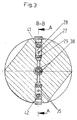
- the basic idea of the invention is training a working cylinder with integrated mechanical locking the translatory movement of a hollow piston rod, which is coupled to a pierced piston, wherein the inside of the bore of the piston has a thread, the one with an external thread, inside the hollow piston rod arranged with a threaded spindle Coupling profile is engaged at its lower end, and a movable locking disc on the coupling profile, with a ring gear on the underside, form-fitting is axially displaceably mounted on a sprocket the top of a fixed locking washer in the bottom part of the Working cylinders in a pressureless state with each other are coupled, the two sprockets of the Locking washers have a positive locking that inhibits the first ring gear or form a positive coupling.
- the axial gear ring can be advantageous Change sliding locking washer for repair purposes.
- the thread pairing between the piston and the threaded spindle is preferably a non-self-locking thread used with a large incline to ensure smooth, free rotation of the threaded spindle, which in high quality Plain bearings is supported.
- the slope of the Thread determined depending on the value of the piston rod acting force and the coefficients of friction between the functional parts of the working cylinder the value of resulting negative reverse torque.
- the locking device is pressure-dependent. It is through a control integrated in the bottom part of the working cylinder always put into the blocked state when there is no operating pressure a fluid is present or the pressure fails.
- the locking device is first released by the spring-loaded, axially movable locking disk with the ring gear by means of an unlocking piston via plunger opposite the ring gear of the fixed locking disc is raised so far that only after that the movement of the main piston of the working cylinder is made possible.
- the control integrated in the base part of the working cylinder that for that essentially from the rotating lead screw and the two locking washers with sprockets existing, mechanical locking system works, works with the normal operating pressure of the working cylinder.
- the Control has one in the main axis of the working cylinder Slightly displaceable around a central position against spring forces Middle slide with fluid return channels on the is in neutral neutral position when depressurized, this fluid return channels with the unlocking piston chamber communicate with the unlocking piston chamber Depressurise so that it unlocked Fluid into the respective flow-oriented connection Check valves flow out and through the spring preload the axially movable locking disc over this and the plunger the unlocking piston is pressed into its starting position becomes.
- the pressurized flows first Fluid through the channels leading to the unlocking piston chamber and piston chamber of the working cylinder.
- these Channels are non-return valves with a defined preload installed, which initially discharges into the piston chambers prevent, with the extent of the pressure increase, only the Middle slide is moved to its end position, and after that the unlocking piston is pressurized.
- the unlocking piston moves the movable locking disc via ram against the action of the locking spring so that the unlocked state is given.
- the preload valves that prevent the fluid from flowing into the prevent each piston chamber are in their preload set 10% higher than the preloaded check valves, which the free inflow into the unlocking piston chamber prevent. In this way, the safe guarantee for the onset of movement of the piston only after it has been completed Unlocking the form lock given.
- the preload valves leading to the piston chambers of the working cylinder lead to the outflow of the fluid from the respective Piston chamber check valves connected in parallel.
- the cylinder tube is double-walled with channels formed on the inner tube, whereby the fluid to as also from the piston rod area without additional external lines via the control in the bottom part of the working cylinder is directed.
- Size of the axial force of the spring for the preload of the axially movable locking washer be dimensioned so that this with sufficient locking quality, taking into account that on the working cylinder dynamic loads, at least corresponds to the return torque impressed by the external load.
- the displacement of the unlocking piston is advantageous Ensuring that it can be moved freely without oil held by inevitable leak oil on every stroke the unlocking piston to unlock the form or frictional coupling of the two ring gears of the locking washers through one in the central axis of the working cylinder arranged leak oil line via a check valve in the fluid circuit is pushed back.
- the advantages of the invention are in particular the reliable, immediate blocking of the movement of the piston rod of the working cylinder when pressure is not present Fluid.
- the current position of the piston rod is without braking distance fixed.
- the twisting of the working cylinder is caused by flattening on the bottom part. and corresponding counterparts at the installation site prevented, or in simple execution via the thru axle the spherical bearing.
- the size of the working cylinder with mechanical path locking does not differ in the radial dimensions and in the axial dimensions only slightly of those a comparable working cylinder without blocking.
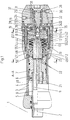
- a working cylinder 1 with its Main axis 2 in a double-walled cylinder tube 3 with Channels 4 and radial groove 5 a piston 6 with an internal thread 7, which is coupled to a hollow piston rod 8, on.
- a threaded spindle 9 at its lower end Square 10 for positive coupling with a sliding Locking disk 11 with a first ring gear 12, which is pre-tensioned by means of locking spring 13, integrally formed is.
- an unlocking piston 15 which via plunger 16 (16.1; 16.2) the first ring gear 12 with the axially displaceable Locking disc 11 from a second ring gear 17 a fixed Locking disk 18 presses are in the threaded spindle 9 in the area the displacement 14 has a bore 19 in the main axis 2 a check valve 20 and with an axial bore 21 in Connected radial bores 22 are arranged.
- a drain port 30 that communicates with a room 31, via a lower connecting line 32, an outer one Ring channel 33 and a line 34 with an oil return Valve communicates with valve chamber 35 a center slide 36 for controlling the pressurization of the unlocking piston 15 is arranged.
- the central slide 36 is depressurized by springs 37 held in the defined middle position, being over its backflow channels 38 and a backflow bore 39 a Connection between an unlocking piston chamber 40 and the check valves 29; 35 exists.
- an oil return-leading locking tube 42 which according to FIG. 5 and FIG. 6 a non-parallel check valve 43 (43.1; 43.2) is switched, which via an annular chamber 44 and a bore 45 (45.1; 45.2) in the locking tube 41; 42 opens arranged.
- the upper locking tube 41 is shown in FIGS. 1 and 2 via a left annular chamber 46 and lines 47 (47.1; 47.2) with the channels 4 in the double-walled cylinder tube 3 and thus further via the radial groove 5 with a piston rod space 48 connected.
- the oil return leading Locking tube 42 is connected via a further line 49 to a Piston chamber 50 connected.
- the mechanical locking system in one double acting Working cylinder 1 lies in its main axis 2, wherein the autonomous control is arranged in the bottom part 23 and only by the pressure of the inflow and outflow of the fluid to the normal operation is operated. It essentially exists from a threaded spindle 9, an axially displaceable Locking disc 11 with a first ring gear 12 which on the Square 10 is secured against rotation, positively and a fixed locking disk 18 with a second ring gear 17.
- the working cylinder 1 is depressurized, the teeth are of the first ring gear 12 of the displaceable locking disk 11 and that of the second ring gear 17 of the fixed locking disk 18 engaged, positively coupled, the sliding Locking disc 11 by means of the locking spring 13 in this Locked position on the square 10 was moved.
- the sliding locking disk 11 and the fixed locking disk 18 with the sprockets 12; 17, the mating of the thread the threaded spindle 9 with the internal thread 7 of the piston 6 and the locking spring 13 are the crucial functional elements of the mechanical locking system, the locking, positive engagement of the teeth of the two sprockets 12; 17 works as a mold. It is sized that it is against the action of the reverse torque, which over the coupling of the internal thread 7 of the piston 6 with the threaded spindle 9 due to external forces on the piston rod 8 arises, a sufficient rest quality is guaranteed.
- the firm Lock washer 18 is in a known manner with the bottom part 23 detachable, but non-positively and positively connected.
- the pressurized port 24 is the pressurized Fluid is introduced and enters via the upper line 25 the inner annulus 26 from which it continues through the upper Connection line 27 into the upper check valve chamber 28 arrives, which enables the outflow into the upper locking tube 41.
- the locking tubes 41; 42 a biasing valve 55 (55.1; 55.2).
- the blocking tubes 41; 42 are the check valves 43.1; 43.2 switched antiparallel to the backflow out the respective run-oriented piston rod space 48 or To allow piston chamber 50.
- the preload of the preload valves 55.1; 55.2 is dimensioned so that the guarantee for it is given that the central slide 36, which is in the unpressurized Condition via the springs 37 in a defined central position is held when the piston rod 8 is retracted into its right end position is pressed before the preload valve 55.1 the fluid via line 47.1, channels 4 and the radial groove 5 can flow into the piston rod space 48.
- the central slide 36 In the right end position of the central slide 36 are Reverse flow channels 38 moved so that the unlocking piston 15 are pressurized to be pressurized with the fluid can.
- Piston 6 which has its internal thread 7 with the thread of Threaded spindle 9 is in positive coupling, results their rotating movement and thus that of the Square 10 positively coupled sliding locking disc 11.
- the movement of the piston 6 and with it coupled piston rod 8 always causes a rotation of the Threaded spindle 9 and the elements coupled to it.
- the size of the force of the locking spring 13 is dimensioned so that this is due to the effect of an external Load on the piston rod 8 via the rotating threaded spindle 9 brought back torque held against rotation becomes.
- Leakage oil from the displacement 14 and the area of the locking spring 13 are known in each stroke of the unlocking piston 15 Way through the check valve 20 in the piston chamber 50 dissipated.
Landscapes
- Engineering & Computer Science (AREA)
- Physics & Mathematics (AREA)
- Fluid Mechanics (AREA)
- Mechanical Engineering (AREA)
- General Engineering & Computer Science (AREA)
- Actuator (AREA)
- Optical Record Carriers And Manufacture Thereof (AREA)
- Pens And Brushes (AREA)
- Mutual Connection Of Rods And Tubes (AREA)
- Vehicle Body Suspensions (AREA)
Claims (4)
- Vérin (1) actionné par un fluide sous pression, comportant un blocage mécanique intégré, bloquant en fonction de la pression le mouvement de translation d'une tige de piston (8), un dispositif commandant l'entrée et la sortie d'un fluide sous pression, un tube cylindrique (3) à double paroi, une pièce de fond (23) avec un disque de serrage fixe (18), un guidage de la tige (8), partiellement creuse, d'un piston percé (6) dont le perçage comporte un filetage intérieur (7) coopérant avec le filetage d'une broche filetée (9) dont l'extrémité inférieure comporte un profil de couplage sur lequel peut coulisser axialement par combinaison de formes un disque de blocage (11) qui, en l'absence de pression, est accouplé par précontrainte élastique au disque de blocage (18) fixe situé dans la pièce de fond (24) du vérin (1),
caractérisé en ce quele disque de blocage (11), par une première couronne dentée (12) est accouplé par combinaison de formes à une seconde couronne dentée (17) du disque de blocage (18),dans la pièce de fond (23) est monté pour commander en fonction de la pression du fluide de fonctionnement du vérin (1), l'accouplement par combinaison de formes des deux couronnes dentées (12, 17) des disques de blocage (11, 18), un dispositif de commande qui travaille sans élément de commande extérieur supplémentaire et ne comporte aucun branchement de pression séparé, et dont un déblocage sans force est assuré par un piston de déverrouillage (15) à l'aide de soupapes de précontrainte (55) et d'un tiroir central (35), de même que par la sollicitation de la chambre de tige de piston (48) ou de la chambre de piston (50) par le fluide sous pression seulement après le déverrouillage du système de blocage. - Vérin selon la revendication 1,
caractérisé en ce que
l'appariement du filetage extérieur (7) du piston (6) et du filetage de la broche filetée (9) est assuré par un filetage non autobloquant à pente importante. - Vérin selon l'une quelconque des revendications 1 ou 2,
caractérisé en ce qu'
un couplage par des garnitures de friction est assuré entre le disque de blocage coulissant (11) et le disque de blocage fixe (18). - Vérin selon l'une quelconque des revendications 1 à 3,
caractérisé en ce qu'
une chambre de déplacement (14) d'un piston de déverrouillage (15) est maintenue sans fluide hydraulique par son effet de refoulement pendant le déverrouillage.
Applications Claiming Priority (2)
| Application Number | Priority Date | Filing Date | Title |
|---|---|---|---|
| DE20011789U | 2000-07-06 | ||
| DE20011789U DE20011789U1 (de) | 2000-07-06 | 2000-07-06 | Druckmittelbetriebener Arbeitszylinder mit mechanischer Wegsperrung im drucklosen Zustand |
Publications (2)
| Publication Number | Publication Date |
|---|---|
| EP1170512A1 EP1170512A1 (fr) | 2002-01-09 |
| EP1170512B1 true EP1170512B1 (fr) | 2004-01-21 |
Family
ID=7943648
Family Applications (1)
| Application Number | Title | Priority Date | Filing Date |
|---|---|---|---|
| EP01114451A Expired - Lifetime EP1170512B1 (fr) | 2000-07-06 | 2001-06-15 | Vérin à fluide sous pression avec verrouillage mécanique lorsque non pressurisé |
Country Status (3)
| Country | Link |
|---|---|
| EP (1) | EP1170512B1 (fr) |
| AT (1) | ATE258275T1 (fr) |
| DE (2) | DE20011789U1 (fr) |
Cited By (1)
| Publication number | Priority date | Publication date | Assignee | Title |
|---|---|---|---|---|
| DE102006030617B4 (de) * | 2005-12-29 | 2009-09-10 | Bümach Engineering International B.V. | Druckmittelbetriebener Arbeitszylinder mit mechanischer Wegsperrung im drucklosen Zustand |
Families Citing this family (5)
| Publication number | Priority date | Publication date | Assignee | Title |
|---|---|---|---|---|
| ITTO20011066A1 (it) * | 2001-11-13 | 2002-02-13 | Rolfo Spa | Attuatore lineare con bloccaggio meccanico interno. |
| DE20216197U1 (de) * | 2002-10-22 | 2004-03-04 | Bümach Engineering International B.V. | Hydraulischer Arbeitszylinder |
| DE102004022203B3 (de) * | 2004-05-05 | 2005-08-11 | Neumeister Hydraulik Gmbh | Verriegelungszylinder mit Gewinde-Freilauf |
| DE202004009302U1 (de) | 2004-06-11 | 2004-08-26 | Bümach Engineering International B.V. | Druckmittelbetriebener Arbeitszylinder mit mechanischer Wegsperrung im drucklosen Zustand |
| DE202005020365U1 (de) | 2005-12-29 | 2006-02-23 | Bümach Engineering International B.V. | Druckmittelbetriebener Arbeitszylinder mit mechanischer Wegsperrung im drucklosen Zustand |
Family Cites Families (9)
| Publication number | Priority date | Publication date | Assignee | Title |
|---|---|---|---|---|
| GB683633A (en) * | 1949-02-25 | 1952-12-03 | Gen Motors Corp | Improved fluid-pressure actuator |
| GB725003A (en) * | 1952-03-27 | 1955-03-02 | Gen Motors Corp | Improved fluid-pressure actuator |
| US2804053A (en) * | 1954-04-14 | 1957-08-27 | Gen Motors Corp | Actuator and locking means therefor |
| US2879746A (en) * | 1955-12-08 | 1959-03-31 | Gen Motors Corp | Actuator with unidirectional locking means |
| US3442176A (en) * | 1967-05-01 | 1969-05-06 | Gen Electric | Actuator locking mechanism |
| IT1271509B (it) * | 1993-10-06 | 1997-05-30 | Luciano Migliori | Attuatore pneumatico lineare con freno ad azione reversibile |
| JPH08303410A (ja) * | 1995-04-27 | 1996-11-19 | Hino Motors Ltd | 流体圧シリンダ |
| DE29720838U1 (de) * | 1997-11-25 | 1998-02-26 | Andexser Lucie | Arbeitszylinder mit integrierter Hubbremse |
| AT4094U1 (de) * | 1999-12-07 | 2001-01-25 | Weber Hydraulik Gmbh | Linearverstellantrieb |
-
2000
- 2000-07-06 DE DE20011789U patent/DE20011789U1/de not_active Expired - Lifetime
-
2001
- 2001-06-15 EP EP01114451A patent/EP1170512B1/fr not_active Expired - Lifetime
- 2001-06-15 DE DE50101349T patent/DE50101349D1/de not_active Expired - Fee Related
- 2001-06-15 AT AT01114451T patent/ATE258275T1/de not_active IP Right Cessation
Cited By (1)
| Publication number | Priority date | Publication date | Assignee | Title |
|---|---|---|---|---|
| DE102006030617B4 (de) * | 2005-12-29 | 2009-09-10 | Bümach Engineering International B.V. | Druckmittelbetriebener Arbeitszylinder mit mechanischer Wegsperrung im drucklosen Zustand |
Also Published As
| Publication number | Publication date |
|---|---|
| DE20011789U1 (de) | 2000-12-21 |
| DE50101349D1 (de) | 2004-02-26 |
| ATE258275T1 (de) | 2004-02-15 |
| EP1170512A1 (fr) | 2002-01-09 |
Similar Documents
| Publication | Publication Date | Title |
|---|---|---|
| EP1995471B1 (fr) | Cylindre verrouillable à palier fluidique | |
| EP2570679B1 (fr) | Vérin de verrouillage et procédés de verrouillage et de déverrouillage correspondants | |
| EP3101283B1 (fr) | Cylindre de verrouillage a double action et son procede de fonctionnement | |
| EP1776527B1 (fr) | Dispositif de verrouillage pour des actionneurs lineaires | |
| EP1170512B1 (fr) | Vérin à fluide sous pression avec verrouillage mécanique lorsque non pressurisé | |
| EP2039944B1 (fr) | Actionneur linéaire, en particulier unité cylindre-piston dotée d'un dispositif de verrouillage | |
| EP0505349B2 (fr) | Vérin hydraulique | |
| EP1605171B1 (fr) | Vérin à fluide sous pression avec bloquage mécanique | |
| DE10356598B3 (de) | Verriegelungszylinder | |
| DE10356596B3 (de) | Verriegelungszylinder | |
| DE102016119251A1 (de) | Hydromechanischer Verriegelungszylinder und hydraulisches Steuersystem zu dessen Betätigung | |
| DE3718246C1 (de) | Hubbegrenzungsvorrichtung fuer den Druckkolben zur Reibungskupplung in einer Kupplungsspindelpresse | |
| EP0457030A1 (fr) | Cylindre de frein à ressort pour freins actionnés par moyen de pression pour véhicules routiers | |
| DE10356597B3 (de) | Verriegelungszylinder | |
| DE202005020365U1 (de) | Druckmittelbetriebener Arbeitszylinder mit mechanischer Wegsperrung im drucklosen Zustand | |
| EP2628960B1 (fr) | Clapet anti-retour hydraulique | |
| DE4224247C1 (de) | Absperrschieber | |
| DE2041390C3 (de) | Doppeltwirkender Arbeitszylinder | |
| DE102006030617B4 (de) | Druckmittelbetriebener Arbeitszylinder mit mechanischer Wegsperrung im drucklosen Zustand | |
| DE1169780B (de) | Hydraulischer Stellzylinder mit Verriegelungs-einrichtung | |
| EP1517049A2 (fr) | Cylindre pneumatique verrouillable | |
| DE2945221A1 (de) | Arbeitszylinder | |
| DE1074361B (de) | Selbsthemmende Spanneinrichtung für Werkzeugmaschinen, insbesondere für Drehbänke |
Legal Events
| Date | Code | Title | Description |
|---|---|---|---|
| PUAI | Public reference made under article 153(3) epc to a published international application that has entered the european phase |
Free format text: ORIGINAL CODE: 0009012 |
|
| 17P | Request for examination filed |
Effective date: 20010615 |
|
| AK | Designated contracting states |
Kind code of ref document: A1 Designated state(s): AT BE CH CY DE DK ES FI FR GB GR IE IT LI LU MC NL PT SE TR Kind code of ref document: A1 Designated state(s): AT DE FR GB IT NL |
|
| AX | Request for extension of the european patent |
Free format text: AL;LT;LV;MK;RO;SI |
|
| GBC | Gb: translation of claims filed (gb section 78(7)/1977) | ||
| EL | Fr: translation of claims filed | ||
| TCNL | Nl: translation of patent claims filed | ||
| AKX | Designation fees paid |
Free format text: AT DE FR GB IT NL |
|
| 17Q | First examination report despatched |
Effective date: 20030204 |
|
| GRAP | Despatch of communication of intention to grant a patent |
Free format text: ORIGINAL CODE: EPIDOSNIGR1 |
|
| GRAS | Grant fee paid |
Free format text: ORIGINAL CODE: EPIDOSNIGR3 |
|
| GRAA | (expected) grant |
Free format text: ORIGINAL CODE: 0009210 |
|
| AK | Designated contracting states |
Kind code of ref document: B1 Designated state(s): AT DE FR GB IT NL |
|
| REG | Reference to a national code |
Ref country code: GB Ref legal event code: FG4D Free format text: NOT ENGLISH |
|
| GBT | Gb: translation of ep patent filed (gb section 77(6)(a)/1977) |
Effective date: 20040121 |
|
| REG | Reference to a national code |
Ref country code: IE Ref legal event code: FG4D Free format text: GERMAN |
|
| REF | Corresponds to: |
Ref document number: 50101349 Country of ref document: DE Date of ref document: 20040226 Kind code of ref document: P |
|
| REG | Reference to a national code |
Ref country code: IE Ref legal event code: FD4D |
|
| ET | Fr: translation filed | ||
| PLBE | No opposition filed within time limit |
Free format text: ORIGINAL CODE: 0009261 |
|
| STAA | Information on the status of an ep patent application or granted ep patent |
Free format text: STATUS: NO OPPOSITION FILED WITHIN TIME LIMIT |
|
| 26N | No opposition filed |
Effective date: 20041022 |
|
| PGFP | Annual fee paid to national office [announced via postgrant information from national office to epo] |
Ref country code: NL Payment date: 20090630 Year of fee payment: 9 |
|
| PGFP | Annual fee paid to national office [announced via postgrant information from national office to epo] |
Ref country code: AT Payment date: 20090615 Year of fee payment: 9 Ref country code: IT Payment date: 20090617 Year of fee payment: 9 |
|
| PGFP | Annual fee paid to national office [announced via postgrant information from national office to epo] |
Ref country code: FR Payment date: 20090625 Year of fee payment: 9 |
|
| PGFP | Annual fee paid to national office [announced via postgrant information from national office to epo] |
Ref country code: DE Payment date: 20090630 Year of fee payment: 9 Ref country code: GB Payment date: 20090610 Year of fee payment: 9 |
|
| REG | Reference to a national code |
Ref country code: NL Ref legal event code: V1 Effective date: 20110101 |
|
| GBPC | Gb: european patent ceased through non-payment of renewal fee |
Effective date: 20100615 |
|
| REG | Reference to a national code |
Ref country code: FR Ref legal event code: ST Effective date: 20110228 |
|
| PG25 | Lapsed in a contracting state [announced via postgrant information from national office to epo] |
Ref country code: IT Free format text: LAPSE BECAUSE OF NON-PAYMENT OF DUE FEES Effective date: 20100615 |
|
| PG25 | Lapsed in a contracting state [announced via postgrant information from national office to epo] |
Ref country code: DE Free format text: LAPSE BECAUSE OF NON-PAYMENT OF DUE FEES Effective date: 20110101 |
|
| PG25 | Lapsed in a contracting state [announced via postgrant information from national office to epo] |
Ref country code: FR Free format text: LAPSE BECAUSE OF NON-PAYMENT OF DUE FEES Effective date: 20100630 Ref country code: NL Free format text: LAPSE BECAUSE OF NON-PAYMENT OF DUE FEES Effective date: 20110101 Ref country code: AT Free format text: LAPSE BECAUSE OF NON-PAYMENT OF DUE FEES Effective date: 20100615 |
|
| PG25 | Lapsed in a contracting state [announced via postgrant information from national office to epo] |
Ref country code: GB Free format text: LAPSE BECAUSE OF NON-PAYMENT OF DUE FEES Effective date: 20100615 |