EP1170512B1 - Fluid pressure actuator with mechanical locking device when unpressurized - Google Patents
Fluid pressure actuator with mechanical locking device when unpressurized Download PDFInfo
- Publication number
- EP1170512B1 EP1170512B1 EP01114451A EP01114451A EP1170512B1 EP 1170512 B1 EP1170512 B1 EP 1170512B1 EP 01114451 A EP01114451 A EP 01114451A EP 01114451 A EP01114451 A EP 01114451A EP 1170512 B1 EP1170512 B1 EP 1170512B1
- Authority
- EP
- European Patent Office
- Prior art keywords
- piston
- locking
- working cylinder
- piston rod
- unlocking
- Prior art date
- Legal status (The legal status is an assumption and is not a legal conclusion. Google has not performed a legal analysis and makes no representation as to the accuracy of the status listed.)
- Expired - Lifetime
Links
Images


Classifications
-
- F—MECHANICAL ENGINEERING; LIGHTING; HEATING; WEAPONS; BLASTING
- F15—FLUID-PRESSURE ACTUATORS; HYDRAULICS OR PNEUMATICS IN GENERAL
- F15B—SYSTEMS ACTING BY MEANS OF FLUIDS IN GENERAL; FLUID-PRESSURE ACTUATORS, e.g. SERVOMOTORS; DETAILS OF FLUID-PRESSURE SYSTEMS, NOT OTHERWISE PROVIDED FOR
- F15B15/00—Fluid-actuated devices for displacing a member from one position to another; Gearing associated therewith
- F15B15/20—Other details, e.g. assembly with regulating devices
- F15B15/26—Locking mechanisms
- F15B15/261—Locking mechanisms using positive interengagement, e.g. balls and grooves, for locking in the end positions
-
- F—MECHANICAL ENGINEERING; LIGHTING; HEATING; WEAPONS; BLASTING
- F15—FLUID-PRESSURE ACTUATORS; HYDRAULICS OR PNEUMATICS IN GENERAL
- F15B—SYSTEMS ACTING BY MEANS OF FLUIDS IN GENERAL; FLUID-PRESSURE ACTUATORS, e.g. SERVOMOTORS; DETAILS OF FLUID-PRESSURE SYSTEMS, NOT OTHERWISE PROVIDED FOR
- F15B15/00—Fluid-actuated devices for displacing a member from one position to another; Gearing associated therewith
- F15B15/20—Other details, e.g. assembly with regulating devices
- F15B15/26—Locking mechanisms
- F15B15/262—Locking mechanisms using friction, e.g. brake pads
- F15B15/264—Screw mechanisms attached to the piston
Definitions
- the invention relates to a working cylinder with mechanical Path blocking for use in hydraulic or pneumatic operated mechanisms, their movement in the event of failure the pressure energy through a mechanically acting locking system is hindered.
- a device for clamping an axially moving rod is also disclosed in the publication DE 37 07 046 A1.
- the clamping takes place by means of a clamping sleeve with outer cone, on which the inner cone is spring-loaded standing piston acts.
- a special version of a continuously adjustable working cylinder who is able to take his position under To hold the load reliably in any intermediate position, is disclosed in the document DE 38 07 669 C2. achieved this effect is achieved by means of a hollow piston rod an inner profile in which a slidable, axial spring-loaded rod with a ball recirculation channel with balls, which engage in the profiling of the piston rod, is arranged.
- the rod is with an actuating piston connected in an actuating cylinder that the rod at Pressurization with the pressure medium of the working cylinder so that the balls run freely can and in the event of pressure drop brought into the blocking position the piston rod will continue to move is hindered.
- the document DE 297 20 838 U1 describes a working cylinder with integrated lifting brake, which essentially consists of a brake cone and a brake piston, whereby in the depressurized state, a non-positive coupling between this is present.
- the brake cone is with a through the working piston movement by means of a spindle nut, driven, Threaded spindle connected in the hollow piston rod.
- the brake piston with a compression spring in a spring chamber is arranged in the bottom closure part. For releasing the lifting brake this will be for the actuation of the working cylinder existing print medium is used by using a 4/3 Valve and a separate connection on the working cylinder is guided into the piston chamber of the brake piston and this removed from the brake cone against the spring preload becomes.
- a pneumatic working cylinder for presetting the cylinder with active or passive brake is in the publication EP 0 648 942 A1.
- a hollow piston rod with a working piston with a threaded sleeve a threaded rod arranged with a brake disc is connected, their rotation and thus the piston movement, is braked or blocked by means of a friction element.
- the friction element is located on a locking element two interconnected piston elements in one separate piston chamber with its own connection for the Print medium are arranged displaceably.
- Dependent on the brake can be used during the installation of the Working cylinder designed as an active or passive brake his. In any case, to release or apply the brake an additional, separately controlled pressure medium connection required.
- the position of the working piston is with the help a signal generator coupled to the threaded rod evaluated. Due to the type of execution as well as the interaction of the brake disc and friction element is one Working cylinders also only when necessary Locking torques can be used sensibly.
- the document US 2 879 746 proposes 2 versions of one Working cylinder with means for mechanically locking the Piston movement before.
- a working piston with hollow piston rod, spindle nut, threaded spindle and a brake element connected thereto Form of a disc available.
- a frictional connection is established between the shoulder of the brake disc and one firmly in the Working cylinder arranged counterpart by means of a Spring preload, specially designed piston, with its own piston chamber and separate pressure medium supply, a frictional connection is established.
- the brake is released by pressurizing the specially trained Piston, which is axially displaced.
- the proposed one Working cylinder with mechanical locking by means of Friction is only for applications with low locking torques suitable.
- US Pat. No. 3,442,176 a elaborate cylinder lock system in the form of a, only ratchet lock acting in one direction of rotation, with a Working piston with spindle nut, hollow piston rod, threaded spindle, in which a loose extension rod from the closed End of the piston rod can be moved and a locking mechanism mounted thereon.
- the ratchet lock is made from a first one, on wedges axially displaceable, ratchet wheel on a disc on the Threaded spindle and one, in the locking part of the cylinder assembled, second ratchet wheel formed. If the teeth the ratchet wheels are engaged, the threaded spindle can only turn in one direction, gradually.
- Both ratchet wheels are spring-loaded from each other kept separate, with a small piston rod a special piston in a separate piston chamber one, arranged in this spring, an axial displacement the disc with the first ratchet wheel.
- This spring acts as a second spring, with higher preload, in a drilled piston chamber of a second special Towards the piston on the sliding ratchet wheel.
- the second special piston is from the loose extension rod then shifted when the piston rod of the working cylinder is in a predetermined position when retracting, whereby the second special piston with the Disc of the ratchet wheel until it engages with the fixed one Ratchet wheel moves and the piston rod extends again is prevented.
- To extend the piston rod First the piston chamber of the special piston with pressure medium acted upon so that the engaged Ratchet wheels are separated and only then the cylinder space to extend the piston rod by means of a necessary Hydraulic reversal pressurized.
- the object of the invention is a pressure medium operated Working cylinders with mechanical path locking develop, the locking device integrated in the working cylinder which is accurate positioning and instant reliable blocking in the event of pressure loss guaranteed, no additional auxiliary energy as well as additional external Control elements and control lines for the and locking requires a compact design as well allows.
- the basic idea of the invention is training a working cylinder with integrated mechanical locking the translatory movement of a hollow piston rod, which is coupled to a pierced piston, wherein the inside of the bore of the piston has a thread, the one with an external thread, inside the hollow piston rod arranged with a threaded spindle Coupling profile is engaged at its lower end, and a movable locking disc on the coupling profile, with a ring gear on the underside, form-fitting is axially displaceably mounted on a sprocket the top of a fixed locking washer in the bottom part of the Working cylinders in a pressureless state with each other are coupled, the two sprockets of the Locking washers have a positive locking that inhibits the first ring gear or form a positive coupling.
- the axial gear ring can be advantageous Change sliding locking washer for repair purposes.
- the thread pairing between the piston and the threaded spindle is preferably a non-self-locking thread used with a large incline to ensure smooth, free rotation of the threaded spindle, which in high quality Plain bearings is supported.
- the slope of the Thread determined depending on the value of the piston rod acting force and the coefficients of friction between the functional parts of the working cylinder the value of resulting negative reverse torque.
- the locking device is pressure-dependent. It is through a control integrated in the bottom part of the working cylinder always put into the blocked state when there is no operating pressure a fluid is present or the pressure fails.
- the locking device is first released by the spring-loaded, axially movable locking disk with the ring gear by means of an unlocking piston via plunger opposite the ring gear of the fixed locking disc is raised so far that only after that the movement of the main piston of the working cylinder is made possible.
- the control integrated in the base part of the working cylinder that for that essentially from the rotating lead screw and the two locking washers with sprockets existing, mechanical locking system works, works with the normal operating pressure of the working cylinder.
- the Control has one in the main axis of the working cylinder Slightly displaceable around a central position against spring forces Middle slide with fluid return channels on the is in neutral neutral position when depressurized, this fluid return channels with the unlocking piston chamber communicate with the unlocking piston chamber Depressurise so that it unlocked Fluid into the respective flow-oriented connection Check valves flow out and through the spring preload the axially movable locking disc over this and the plunger the unlocking piston is pressed into its starting position becomes.
- the pressurized flows first Fluid through the channels leading to the unlocking piston chamber and piston chamber of the working cylinder.
- these Channels are non-return valves with a defined preload installed, which initially discharges into the piston chambers prevent, with the extent of the pressure increase, only the Middle slide is moved to its end position, and after that the unlocking piston is pressurized.
- the unlocking piston moves the movable locking disc via ram against the action of the locking spring so that the unlocked state is given.
- the preload valves that prevent the fluid from flowing into the prevent each piston chamber are in their preload set 10% higher than the preloaded check valves, which the free inflow into the unlocking piston chamber prevent. In this way, the safe guarantee for the onset of movement of the piston only after it has been completed Unlocking the form lock given.
- the preload valves leading to the piston chambers of the working cylinder lead to the outflow of the fluid from the respective Piston chamber check valves connected in parallel.
- the cylinder tube is double-walled with channels formed on the inner tube, whereby the fluid to as also from the piston rod area without additional external lines via the control in the bottom part of the working cylinder is directed.
- Size of the axial force of the spring for the preload of the axially movable locking washer be dimensioned so that this with sufficient locking quality, taking into account that on the working cylinder dynamic loads, at least corresponds to the return torque impressed by the external load.
- the displacement of the unlocking piston is advantageous Ensuring that it can be moved freely without oil held by inevitable leak oil on every stroke the unlocking piston to unlock the form or frictional coupling of the two ring gears of the locking washers through one in the central axis of the working cylinder arranged leak oil line via a check valve in the fluid circuit is pushed back.
- the advantages of the invention are in particular the reliable, immediate blocking of the movement of the piston rod of the working cylinder when pressure is not present Fluid.
- the current position of the piston rod is without braking distance fixed.
- the twisting of the working cylinder is caused by flattening on the bottom part. and corresponding counterparts at the installation site prevented, or in simple execution via the thru axle the spherical bearing.
- the size of the working cylinder with mechanical path locking does not differ in the radial dimensions and in the axial dimensions only slightly of those a comparable working cylinder without blocking.
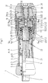
- a working cylinder 1 with its Main axis 2 in a double-walled cylinder tube 3 with Channels 4 and radial groove 5 a piston 6 with an internal thread 7, which is coupled to a hollow piston rod 8, on.
- a threaded spindle 9 at its lower end Square 10 for positive coupling with a sliding Locking disk 11 with a first ring gear 12, which is pre-tensioned by means of locking spring 13, integrally formed is.
- an unlocking piston 15 which via plunger 16 (16.1; 16.2) the first ring gear 12 with the axially displaceable Locking disc 11 from a second ring gear 17 a fixed Locking disk 18 presses are in the threaded spindle 9 in the area the displacement 14 has a bore 19 in the main axis 2 a check valve 20 and with an axial bore 21 in Connected radial bores 22 are arranged.
- a drain port 30 that communicates with a room 31, via a lower connecting line 32, an outer one Ring channel 33 and a line 34 with an oil return Valve communicates with valve chamber 35 a center slide 36 for controlling the pressurization of the unlocking piston 15 is arranged.
- the central slide 36 is depressurized by springs 37 held in the defined middle position, being over its backflow channels 38 and a backflow bore 39 a Connection between an unlocking piston chamber 40 and the check valves 29; 35 exists.
- an oil return-leading locking tube 42 which according to FIG. 5 and FIG. 6 a non-parallel check valve 43 (43.1; 43.2) is switched, which via an annular chamber 44 and a bore 45 (45.1; 45.2) in the locking tube 41; 42 opens arranged.
- the upper locking tube 41 is shown in FIGS. 1 and 2 via a left annular chamber 46 and lines 47 (47.1; 47.2) with the channels 4 in the double-walled cylinder tube 3 and thus further via the radial groove 5 with a piston rod space 48 connected.
- the oil return leading Locking tube 42 is connected via a further line 49 to a Piston chamber 50 connected.
- the mechanical locking system in one double acting Working cylinder 1 lies in its main axis 2, wherein the autonomous control is arranged in the bottom part 23 and only by the pressure of the inflow and outflow of the fluid to the normal operation is operated. It essentially exists from a threaded spindle 9, an axially displaceable Locking disc 11 with a first ring gear 12 which on the Square 10 is secured against rotation, positively and a fixed locking disk 18 with a second ring gear 17.
- the working cylinder 1 is depressurized, the teeth are of the first ring gear 12 of the displaceable locking disk 11 and that of the second ring gear 17 of the fixed locking disk 18 engaged, positively coupled, the sliding Locking disc 11 by means of the locking spring 13 in this Locked position on the square 10 was moved.
- the sliding locking disk 11 and the fixed locking disk 18 with the sprockets 12; 17, the mating of the thread the threaded spindle 9 with the internal thread 7 of the piston 6 and the locking spring 13 are the crucial functional elements of the mechanical locking system, the locking, positive engagement of the teeth of the two sprockets 12; 17 works as a mold. It is sized that it is against the action of the reverse torque, which over the coupling of the internal thread 7 of the piston 6 with the threaded spindle 9 due to external forces on the piston rod 8 arises, a sufficient rest quality is guaranteed.
- the firm Lock washer 18 is in a known manner with the bottom part 23 detachable, but non-positively and positively connected.
- the pressurized port 24 is the pressurized Fluid is introduced and enters via the upper line 25 the inner annulus 26 from which it continues through the upper Connection line 27 into the upper check valve chamber 28 arrives, which enables the outflow into the upper locking tube 41.
- the locking tubes 41; 42 a biasing valve 55 (55.1; 55.2).
- the blocking tubes 41; 42 are the check valves 43.1; 43.2 switched antiparallel to the backflow out the respective run-oriented piston rod space 48 or To allow piston chamber 50.
- the preload of the preload valves 55.1; 55.2 is dimensioned so that the guarantee for it is given that the central slide 36, which is in the unpressurized Condition via the springs 37 in a defined central position is held when the piston rod 8 is retracted into its right end position is pressed before the preload valve 55.1 the fluid via line 47.1, channels 4 and the radial groove 5 can flow into the piston rod space 48.
- the central slide 36 In the right end position of the central slide 36 are Reverse flow channels 38 moved so that the unlocking piston 15 are pressurized to be pressurized with the fluid can.
- Piston 6 which has its internal thread 7 with the thread of Threaded spindle 9 is in positive coupling, results their rotating movement and thus that of the Square 10 positively coupled sliding locking disc 11.
- the movement of the piston 6 and with it coupled piston rod 8 always causes a rotation of the Threaded spindle 9 and the elements coupled to it.
- the size of the force of the locking spring 13 is dimensioned so that this is due to the effect of an external Load on the piston rod 8 via the rotating threaded spindle 9 brought back torque held against rotation becomes.
- Leakage oil from the displacement 14 and the area of the locking spring 13 are known in each stroke of the unlocking piston 15 Way through the check valve 20 in the piston chamber 50 dissipated.
Abstract
Description
Die Erfindung bezeichnet einen Arbeitszylinder mit mechanischer Wegsperrung für den Einsatz in hydraulisch oder pneumatisch betriebenen Mechanismen, deren Bewegung bei Ausfall der Druckenergie durch ein mechanisch wirkendes Sperrsystem gehindert ist.The invention relates to a working cylinder with mechanical Path blocking for use in hydraulic or pneumatic operated mechanisms, their movement in the event of failure the pressure energy through a mechanically acting locking system is hindered.
Aus dem allgemeinen Stand der Technik sind mechanische Sperrsysteme für Arbeitszylinder bekannt, die durch eine form- oder kraftschlüssige Blockierung der Bewegung der Kolbenstange wirken, wobei Systeme mit kraftschlüssiger Blockierung überwiegen. Beispielsweise werden dabei Reibkörper durch Federkräfte auf den inneren oder auch äußeren Mantel der Kolbenstange, oder auch inneren Mantel des Arbeitszylinderrohrs gepresst, um mittels des erzielten Reibschlusses die Bewegung der unter axialer Last stehenden Kolbenstange zu verhindern bzw. zu blockieren.Mechanical are from the general state of the art Locking systems for working cylinders known by a positive or non-positive blocking of the movement of the Piston rod act, systems with non-positive Blockage prevail. For example, friction bodies by spring forces on the inner or outer Jacket of the piston rod, or inner jacket of the working cylinder tube pressed to by means of the frictional engagement achieved the movement of those under axial load To prevent or block the piston rod.
Die Druckschrift DE 35 10 643 A1 beschreibt einen Klemmkopf zur Fixierung einer Stange mittels von Aussen auf diese angreifendem Klemmelement mit schräger Führungsfläche, das von einem mittels Servokolben verschiebbaren, unter Federvorspannung stehendem Spannelement betätigt wird.DE 35 10 643 A1 describes a clamping head for fixing a rod by means of an attack on it from the outside Clamping element with an oblique guide surface, the from a slidable by means of servo pistons, under spring preload standing clamping element is actuated.
Eine ähnliche Lösung einer blockierenden Klemmvorrichtung
wird in der Druckschrift DE 38 11 225 C2 beschrieben. Mehrere
axial in Führungen verschiebbare Klemmbacken werden
durch Federelemente zur Blockierung an die Kolbenstange gepresst.
Die Öffnungslage wird mit einem zylindergeführten
Servokolben erreicht.A similar solution to a blocking clamp
is described in the
Eine Vorrichtung zur Klemmung einer axial bewegten Stange
wird ebenfalls in der Druckschrift DE 37 07 046 A1 offenbart.
Hierbei erfolgt die Klemmung mittels einer Klemmhülse
mit Aussenkonus, auf den der Innenkonus eines unter Federvorspannung
stehenden Kolbens wirkt. A device for clamping an axially moving rod
is also disclosed in the
Diesen beschriebenen Klemmköpfen ist neben einer aufwendigen Fertigung gemeinsam, dass generell bei auftretenden grossen dynamischen Kräften auf Grund der Haftreibung keine genaue Positionierung möglich ist. Nachteilig wirkt sich die Klemmung auch auf die Nutzungsdauer funktioneller Teile, hier der Kolbenstange aus, da durch die Haftreibung ein erheblicher Verschleiss bedingt ist. Die Abmessungen eines Arbeitszylinders mit derartigen Klemmvorrichtungen sind wesentlich grösser bzw. bei ausserhalb des Zylinders angebrachten Klemmvorrichtungen sind diese radial weit ausladend.This described clamping heads is in addition to a complex Manufacturing together that generally occurs when large dynamic forces due to static friction none exact positioning is possible. It has a disadvantageous effect the clamping also on the service life of functional parts, here the piston rod, because of the static friction considerable wear is caused. The dimensions of a Working cylinders with such clamping devices are essential larger or attached outside the cylinder Clamping devices are radially wide.
Mit fast den gleichen Nachteilen des Verschleisses von funktionellen Teilen ist die in der Druckschrift DE 3810183 A1 offenbarte Lösung einer Vorrichtung zur Verriegelung einer Kolbenstange einer Kolben-Zylinderanordnung behaftet. Zur Verriegelung weist der Kolben mittels Federn verschiebbare Scheibensegmente auf, die mittels ringförmiger, kolbenartiger Stellelemente mit konischen Stellelementen auf konische Flächen an den Scheibenflächen gedrückt werden und so die Scheibensegmente gegen den Druck der Federn nach innen ziehen. Im drucklosen Zustand werden die Scheibensegmente gegen den Innenmantel des Zylinderrohrs gepresst und blockieren so die Kolbenbewegung.With almost the same disadvantages of wear from functional parts is that in the publication DE 3810183 A1 disclosed solution of a device for locking a Piston rod of a piston-cylinder arrangement affected. For locking purposes, the piston has slidable springs Disc segments on the ring-shaped, piston-like Control elements with conical control elements conical surfaces are pressed on the disc surfaces and so the disc segments against the pressure of the springs inwards pull. The disc segments are in a depressurized state pressed against the inner jacket of the cylinder tube and block the piston movement.
Eine andere Lösung, bei der die Blockierung der Bewegung
einer Kolbenstange erzielt wird, beschreibt die Druckschrift
DE 33 07 644 A1. In die hohle Kolbenstange ist eine
Vorrichtung zur kraftschlüssigen Klemmung eingebaut, wobei
Klemmsegmente mit Reibbelägen an einem Stützrohr durch einen
Konus an einer Betätigungsstange, die mit einem Steuerkolben
in einem Steuerzylinder verbunden und über eine Feder
in die Klemmstellung vorgespannt ist, zur Blockierung
gegen die Innenwand der Kolbenstange gepresst werden.Another solution where the movement is blocked
a piston rod is achieved, describes the
Eine besondere Ausführung eines stufenlos verstellbaren Arbeitszylinders,
der in der Lage ist, seine Position unter
Last in beliebiger Zwischenstellung zuverlässig zu halten,
wird in der Druckschrift DE 38 07 669 C2 offenbart. Erzielt
wird diese Wirkung mittels einer hohlen Kolbenstange mit
einer Innenprofilierung, in der eine verschiebbare, axial
federbelastete Stange mit einem Kugelumlaufkanal mit Kugeln,
die in die Profilierung der Kolbenstange eingreifen,
angeordnet ist. Die Stange ist mit einem Betätigungskolben
in einem Betätigungszylinder verbunden, der die Stange bei
Druckbeaufschlagung mit dem Druckmedium des Arbeitszylinders
so verschiebt, dass die Kugeln ungehindert umlaufen
können und im Falle des Druckabfalls in Sperrstellung gebracht
werden, somit die Kolbenstange an der weiteren Bewegung
gehindert ist.A special version of a continuously adjustable working cylinder,
who is able to take his position under
To hold the load reliably in any intermediate position,
is disclosed in the
Die Druckschrift DE 297 20 838 U1 beschreibt einen Arbeitszylinder mit integrierter Hubbremse, die im Wesentlichen aus einem Bremskegel und einem Bremskolben besteht, wobei im Drucklosen Zustand eine kraftschlüssige Kopplung zwischen diesen vorliegt. Der Bremskegel ist mit einer, durch die Arbeitskolbenbewegung mittels Spindelmutter, angetriebenen, Gewindespindel in der hohlen Kolbenstange verbunden. Der Bremskolben mit einer Druckfeder in einer Federkammer ist im Bodenverschlussteil angeordnet. Zum Lösen der Hubbremse wird das für die Betätigung des Arbeitszylinders vorhandene Druckmedium genutzt, indem dieses über ein 4/3 Ventil sowie einem separaten Anschluss am Arbeitszylinder in den Kolbenraum des Bremskolben geführt wird und dieser gegen die Vorspannung der Feder vom Bremskegel entfernt wird. Der Druck liegt dabei gleichzeitig am Bremskolben und Arbeitskolben an, so dass die Entriegelung stets unter Last, ohne kraftfreie Entkopplung erfolgt. Grundsätzlich ist diese Ausführung einer Hubbremse, mit in der Nähe der Zentralachse des Arbeitszylinders angeordneter reibschlüssiger Bremse nur für sehr kleine Sperrmomente anwendbar. Ein nach diesem Prinzip ausgeführter Arbeitszylinder für große Sperrmomente, wie sie für schwere Lasten als auch genaue Positionierungen erforderlich sind, müsste mit einer radial weit ausladenden Schraubkappe zur Aufnahme der Hubbremse ausgeführt sein, wodurch eine fertigungs- und kostenaufwändige Konstruktion entstünde, deren praktischer Anwendbarkeit enge Grenzen gesetzt sind.The document DE 297 20 838 U1 describes a working cylinder with integrated lifting brake, which essentially consists of a brake cone and a brake piston, whereby in the depressurized state, a non-positive coupling between this is present. The brake cone is with a through the working piston movement by means of a spindle nut, driven, Threaded spindle connected in the hollow piston rod. The brake piston with a compression spring in a spring chamber is arranged in the bottom closure part. For releasing the lifting brake this will be for the actuation of the working cylinder existing print medium is used by using a 4/3 Valve and a separate connection on the working cylinder is guided into the piston chamber of the brake piston and this removed from the brake cone against the spring preload becomes. The pressure is at the same time on the brake piston and Piston on, so that the release is always under Load without force-free decoupling. in principle is this version of a lifting brake, with near the Central axis of the working cylinder arranged frictionally Brake can only be used for very small locking torques. A working cylinder designed for this principle large locking torques as they are accurate for heavy loads as well Positionings are required, should be done with a radially widely protruding screw cap to accommodate the lifting brake be executed, making a manufacturing and costly Construction would arise, its more practical Applicability is limited.
Ein Pneumatik-Arbeitszylinder zur Voreinstellung des Zylinders mit aktiver oder passiver Bremse wird in der Druckschrift EP 0 648 942 A1 offenbart. In einer hohlen Kolbenstange mit einem Arbeitskolben mit einer Gewindemuffe ist eine Gewindestange angeordnet, die mit einer Bremsscheibe verbunden ist, deren Rotation und damit die Kolbenbewegung, mittels eines Reibelements gebremst bzw. gesperrt wird. Das Reibelement befindet sich an einem Feststellelement aus zwei miteinander verbundenen Kolbenelementen, die in einem separaten Kolbenraum mit einem eigenen Anschluss für das Druckmedium verschiebbar angeordnet sind. In Abhängigkeit vom Einsatzzweck kann die Bremse während der Montage des Arbeitszylinders als aktive oder passive Bremse ausgebildet sein. Zum Lösen bzw. Betätigen der Bremse ist in jedem Fall ein zusätzlicher, separat gesteuerter Druckmittelanschluss erforderlich. Die Position des Arbeitskolbens wird mit Hilfe eines mit der Gewindestange gekoppelten Signalgenerators ausgewertet. Auf Grund der Art Ausführung als auch des Zusammenwirkens von Bremsscheibe und Reibelement ist ein derartiger Arbeitszylinder ebenso nur bei notwendigen geringen Sperrmomenten sinnvoll einsetzbar.A pneumatic working cylinder for presetting the cylinder with active or passive brake is in the publication EP 0 648 942 A1. In a hollow piston rod with a working piston with a threaded sleeve a threaded rod arranged with a brake disc is connected, their rotation and thus the piston movement, is braked or blocked by means of a friction element. The The friction element is located on a locking element two interconnected piston elements in one separate piston chamber with its own connection for the Print medium are arranged displaceably. Dependent on the brake can be used during the installation of the Working cylinder designed as an active or passive brake his. In any case, to release or apply the brake an additional, separately controlled pressure medium connection required. The position of the working piston is with the help a signal generator coupled to the threaded rod evaluated. Due to the type of execution as well as the interaction of the brake disc and friction element is one Working cylinders also only when necessary Locking torques can be used sensibly.
Ein weiterer Arbeitszylinder mit Sperrmitteln wird in der Druckschrift US 2 804 053 beschrieben. Dieser weist ebenfalls einen Arbeitskolben mit hohler Kolbenstange, Spindelmutter, Gewindespindel und ein mit dieser verbundenes, axial verschiebbares Bremsenteil in Form einer Bremsscheibe, die unter Federvorspannung mit einem weiteren Bremsenteil in Form eines Reibelements im Drucklosen Zustand im Eingriff steht, auf. Zum Lösen der Bremse ist ein spezieller Lösekolben mit Stößel, der bei Druckbeaufschlagung die Bremsscheibe vom Reibelement abhebt, in einem zusätzlichen Kolbenraum mit separatem Druckmittelanschluss angeordnet. Auch diese aufwändige Lösung ist wegen der Friktionsbremse nur für relativ geringe Sperrmomente geeignet und bedingt einen zusätzlichen Druckmittelanschluss für den Lösekolben sowie eine zusätzliche Ansteuerung.Another cylinder with locking means is in the Document US 2 804 053. This also points a working piston with a hollow piston rod, spindle nut, Threaded spindle and a connected to it, axially displaceable brake part in the form of a brake disc, the under spring preload with another brake part in the form of a friction element in the depressurized state in Intervention stands up. To release the brake is a special one Release piston with plunger, which when pressurized Brake disc stands out from the friction element in an additional Piston chamber with separate pressure medium connection. This complex solution is also due to the friction brake only suitable and limited for relatively low locking torques an additional pressure medium connection for the release piston as well as an additional control.
Die Druckschrift US 2 879 746 schlägt 2 Ausführungen eines Arbeitszylinders mit Mitteln zum mechanischen Sperren der Kolbenbewegung vor. Es sind unter anderem wiederum ein Arbeitskolben mit hohler Kolbenstange, Spindelmutter, Gewindespindel und ein mit dieser verbundenes Bremsenelement in Form einer Scheibe vorhanden. Im drucklosen Zustand wird zwischen der Schulter der Bremsscheibe sowie einem fest im Arbeitszylinder angeordnetem Gegenstück mittels eines unter Federvorspannung stehenden, speziell ausgebildeten Kolbens, mit eigenem Kolbenraum und separater Druckmittelzuführung, ein Reibschluss hergestellt. Das Lösen der Bremse erfolgt durch Druckmittelbeaufschlagung des speziell ausgebildeten Kolbens, wobei dieser axial verschoben wird. Der vorgeschlagene Arbeitszylinder mit mechanischer Sperrung mittels Reibschluss ist nur für Anwendungen mit geringen Sperrmomenten geeignet.The document US 2 879 746 proposes 2 versions of one Working cylinder with means for mechanically locking the Piston movement before. Among other things, there is also a working piston with hollow piston rod, spindle nut, threaded spindle and a brake element connected thereto Form of a disc available. When depressurized between the shoulder of the brake disc and one firmly in the Working cylinder arranged counterpart by means of a Spring preload, specially designed piston, with its own piston chamber and separate pressure medium supply, a frictional connection is established. The brake is released by pressurizing the specially trained Piston, which is axially displaced. The proposed one Working cylinder with mechanical locking by means of Friction is only for applications with low locking torques suitable.
Des Weiteren wird auch in der Druckschrift US 3 442 176 ein aufwändiges Arbeitszylindersperrsystem in Form einer, nur in einer Drehrichtung wirkenden Ratschensperre, mit einem Arbeitskolben mit Spindelmutter, hohler Kolbenstange, Gewindespindel, in der ein loser Verlängerungsstab vom geschlossenen Ende der Kolbenstange verschoben werden kann, und einem an dieser montiertem Sperrmechanismus, beschrieben. Die Ratschensperre wird aus einem ersten, auf Keilen axial verschiebbarem, Ratschenrad an einer Scheibe an der Gewindespindel und einem, im Verschlussteil der Zylinders montiertem, zweiten Ratschenrad gebildet. Wenn die Zähne der Ratschenräder im Eingriff sind, kann sich die Gewindespindel nur in einer Richtung, schrittweise drehen. Die beiden Ratschenräder werden mittels Federvorspannung voneinander getrennt gehalten, wobei eine kleine Kolbenstange eines speziellen Kolbens in einem separaten Kolbenraum mittels einer, in diesem angeordneter Feder, eine axiale Verschiebung der Scheibe mit dem ersten Ratschenrad bewirkt. Dieser Feder wirkt eine zweite Feder, mit höherer Vorspannung, in einem gebohrten Kolbenraum eines zweiten speziellen Kolbens am verschiebbaren Ratschenrad entgegen. Der zweite spezielle Kolben wird vom losen Verlängerungsstab dann verschoben, wenn sich die Kolbenstange des Arbeitszylinders beim Einfahren in einer vorbestimmten Position befindet, wodurch sich der zweite spezielle Kolben mit der Scheibe des Ratschenrades bis zum Eingriff mit dem festen Ratschenrad verschiebt und ein Wiederausfahren der Kolbenstange verhindert wird. Zum Ausfahren der Kolbenstange wird zunächst der Kolbenraum des speziellen Kolbens mit Druckmittel beaufschlagt, so dass die im Eingriff befindlichen Ratschenräder getrennt werden und erst dann der Zylinderraum zum Ausfahren der Kolbenstange mittels einer notwendigen Hydraulikumsteuerung mit dem Druckmittel beaufschlagt.Furthermore, US Pat. No. 3,442,176 a elaborate cylinder lock system in the form of a, only ratchet lock acting in one direction of rotation, with a Working piston with spindle nut, hollow piston rod, threaded spindle, in which a loose extension rod from the closed End of the piston rod can be moved and a locking mechanism mounted thereon. The ratchet lock is made from a first one, on wedges axially displaceable, ratchet wheel on a disc on the Threaded spindle and one, in the locking part of the cylinder assembled, second ratchet wheel formed. If the teeth the ratchet wheels are engaged, the threaded spindle can only turn in one direction, gradually. The Both ratchet wheels are spring-loaded from each other kept separate, with a small piston rod a special piston in a separate piston chamber one, arranged in this spring, an axial displacement the disc with the first ratchet wheel. This spring acts as a second spring, with higher preload, in a drilled piston chamber of a second special Towards the piston on the sliding ratchet wheel. The second special piston is from the loose extension rod then shifted when the piston rod of the working cylinder is in a predetermined position when retracting, whereby the second special piston with the Disc of the ratchet wheel until it engages with the fixed one Ratchet wheel moves and the piston rod extends again is prevented. To extend the piston rod First the piston chamber of the special piston with pressure medium acted upon so that the engaged Ratchet wheels are separated and only then the cylinder space to extend the piston rod by means of a necessary Hydraulic reversal pressurized.
In der Druckschrift GB 683 633 wird ein Arbeitszylinder gemäß Oberbegriff das Anspruchs 1 beschrieben. In GB 683 633 a working cylinder according to the preamble of claim 1.
Die Aufgabe der Erfindung besteht darin, einen druckmittelbetriebenen Arbeitszylinder mit mechanischer Wegsperrung zu entwickeln, dessen Sperrvorrichtung im Arbeitszylinder integriert ist, die eine genaue Positionierung und eine sofortige zuverlässige Sperrung bei Druckausfall gewährleistet, keine zusätzliche Hilfsenergie sowie zusätzliche äussere Steuerungselemente und Steuerleitungen für die Ent- und Verriegelung benötigt als auch eine kompakte Bauweise ermöglicht.The object of the invention is a pressure medium operated Working cylinders with mechanical path locking develop, the locking device integrated in the working cylinder which is accurate positioning and instant reliable blocking in the event of pressure loss guaranteed, no additional auxiliary energy as well as additional external Control elements and control lines for the and locking requires a compact design as well allows.
Die Aufgabe wird durch die im Patentanspruch 1 aufgeführten Merkmale gelöst. Bevorzugte Weiterbildungen ergeben sich aus den Unteransprüchen.The object is achieved by those listed in claim 1 Features solved. Preferred further developments result from the subclaims.
Der Grundgedanke der Erfindung besteht in der Ausbildung eines Arbeitszylinders mit integrierter mechanischer Sperrung der translatorischen Bewegung einer hohlen Kolbenstange, die mit einem durchbohrten Kolben gekoppelt ist, wobei die Innenseite der Bohrung des Kolbens ein Gewinde aufweist, das mit einem Außengewinde einer, im Inneren der hohlen Kolbenstange angeordneten Gewindespindel mit einem Koppelungsprofil an derem unteren Ende im Eingriff steht, und auf dem Koppelungsprofil eine bewegliche Sperrscheibe, mit einem Zahnkranz an deren Unterseite, formschlüssig axial verschiebbar gelagert ist, der mit einem Zahnkranz an der Oberseite einer festen Sperrscheibe im Bodenteil des Arbeitszylinders im drucklosen Zustand formschlüssig miteinander gekoppelt sind, wobei die beiden Zahnkränze der Sperrscheiben eine den ersten Zahnkranz hemmende, formschlüssige oder kraftschlüssige Koppelung bilden.The basic idea of the invention is training a working cylinder with integrated mechanical locking the translatory movement of a hollow piston rod, which is coupled to a pierced piston, wherein the inside of the bore of the piston has a thread, the one with an external thread, inside the hollow piston rod arranged with a threaded spindle Coupling profile is engaged at its lower end, and a movable locking disc on the coupling profile, with a ring gear on the underside, form-fitting is axially displaceably mounted on a sprocket the top of a fixed locking washer in the bottom part of the Working cylinders in a pressureless state with each other are coupled, the two sprockets of the Locking washers have a positive locking that inhibits the first ring gear or form a positive coupling.
Vorteilhaft lässt sich insbesondere der Zahnkranz der axial verschiebbaren Sperrscheibe für Reparaturzwecke wechseln. Für die Gewindepaarung zwischen dem Kolben und der Gewindespindel wird vorzugsweise ein nicht selbsthemmendes Gewinde mit großer Steigung eingesetzt, um eine leichtgängige, freie Drehung der Gewindespindel, die in hochwertigen Gleitlagern gelagert ist, zu ermöglichen. Die Steigung des Gewindes bestimmt in Abhängigkeit vom Wert der auf die Kolbenstange einwirkenden Kraft und den Reibwerten zwischen den funktionellen Teilen des Arbeitszylinders den Wert des resultierenden negativen Rückdrehmoments.In particular, the axial gear ring can be advantageous Change sliding locking washer for repair purposes. For the thread pairing between the piston and the threaded spindle is preferably a non-self-locking thread used with a large incline to ensure smooth, free rotation of the threaded spindle, which in high quality Plain bearings is supported. The slope of the Thread determined depending on the value of the piston rod acting force and the coefficients of friction between the functional parts of the working cylinder the value of resulting negative reverse torque.
Die Sperrvorrichtung wirkt druckabhängig. Sie wird durch eine im Bodenteil des Arbeitszylinders integrierte Steuerung immer dann in den Sperrzustand versetzt, wenn kein Betriebsdruck eines Fluids anliegt oder der Druck ausfällt. Bei Beaufschlagung des Arbeitszylinders mit- dem Betriebsdruck wird zunächst die Sperrvorrichtung gelöst, indem die unter Federvorspannung stehende, axial bewegliche Sperrscheibe mit dem Zahnkranz mittels eines Entriegelungskolbens über Stößel gegenüber dem Zahnkranz der festen Sperrscheibe soweit angehoben wird, dass erst danach die Bewegung des Hauptkolbens des Arbeitszylinders ermöglicht wird. Während der Bewegung des, über die mit der Kolbenstange gekoppelten Teile des zu bewegenden Getriebes, gegen Verdrehen gesicherten Kolbens im Zylinderrohr wird eine Drehung der Gewindespindel mit der formschlüssig gekoppelten, axial beweglichen Sperrscheibe bewirkt. Unabhängig von der Bewegungsrichtung des Kolbens erfolgt bei nicht anliegendem Betriebsdruck eine sofortige mechanische Sperrung der Kolbenbewegung, indem die Drehbewegung der Gewindespindel im Gewinde des Kolbens durch die formschlüssige Koppelung der beiden Zahnkränze der Sperrscheiben blockiert wird. Hierbei ist auch der Zylinderraum des Entriegelungskolbens drucklos, wodurch die unter Federvorspannung stehende, mit der Gewindespindel formschlüssig gekoppelte, axial verschiebbare Sperrscheibe den Entriegelungskolben über die Stößel zurückdrückt und mit dem Zahnkranz gegen den Zahnkranz der festen Sperrscheibe gepresst, eine formschlüssige Koppelung hergestellt wird und die Drehung der Gewindespindel damit sofort sperrt.The locking device is pressure-dependent. It is through a control integrated in the bottom part of the working cylinder always put into the blocked state when there is no operating pressure a fluid is present or the pressure fails. When the working pressure is applied to the working cylinder the locking device is first released by the spring-loaded, axially movable locking disk with the ring gear by means of an unlocking piston via plunger opposite the ring gear of the fixed locking disc is raised so far that only after that the movement of the main piston of the working cylinder is made possible. During the movement of the, coupled with the piston rod Parts of the gear to be moved against twisting secured piston in the cylinder barrel will turn the threaded spindle with the positively coupled, axial movable locking disc causes. Regardless of the direction of movement of the piston occurs when the operating pressure is not present immediate mechanical blocking of the piston movement, by rotating the threaded spindle in the thread of the piston through the positive coupling of the two ring gears of the locking disks is blocked. in this connection the cylinder chamber of the unlocking piston is also depressurized, whereby the spring-loaded, with the Threaded spindle coupled positively, axially displaceable Locking disk presses the unlocking piston back over the plunger and with the ring gear against the ring gear of fixed locking disc pressed, a positive coupling is produced and the rotation of the threaded spindle locks immediately.
Die im Bodenteil des Arbeitszylinders integrierte Steuerung, die für das im Wesentlichen aus der rotierenden Gewindespindel und den beiden Sperrscheiben mit Zahnkränzen bestehende, mechanische Sperrsystem arbeitet, funktioniert mit dem normalen Betriebsdruck des Arbeitszylinders. Die Steuerung weist in der Hauptachse des Arbeitszylinders einen um eine Mittellage gegen Federkräfte gering verschiebbaren Mittelschieber mit Fluidrückführungskanälen auf, der im drucklosen Zustand in neutraler Mittelstellung steht, diese Fluidrückführungskanäle mit dem Entriegelungskolbenraum in Verbindung stehen, den Entriegelungskolbenraum drucklos schalten, damit das die Entriegelung bewirkte Fluid in den jeweils ablauforientierten Anschluss über Rückschlagventile abströmt und durch die Federvorspannung der axial beweglichen Sperrscheibe über diese und die Stößel der Entriegelungskolben in seine Ausgangslage gedrückt wird.The control integrated in the base part of the working cylinder, that for that essentially from the rotating lead screw and the two locking washers with sprockets existing, mechanical locking system works, works with the normal operating pressure of the working cylinder. The Control has one in the main axis of the working cylinder Slightly displaceable around a central position against spring forces Middle slide with fluid return channels on the is in neutral neutral position when depressurized, this fluid return channels with the unlocking piston chamber communicate with the unlocking piston chamber Depressurise so that it unlocked Fluid into the respective flow-oriented connection Check valves flow out and through the spring preload the axially movable locking disc over this and the plunger the unlocking piston is pressed into its starting position becomes.
Beim Entriegelungsvorgang strömt zunächst unter Druck stehendes Fluid über die Kanäle, die zum Entriegelungskolbenraum und Kolbenraum des Arbeitszylinders führen. In diese Kanäle sind jeweils Rückschlagventile mit definierter Vorspannung eingebaut, die den Abstrom in die Kolbenräume vorerst hindern, wobei im Maße der Druckerhöhung, erst der Mittelschieber in seine Endlage verschoben wird, und danach der Entriegelungskolben druckbeaufschlagt. Der Entriegelungskolben verschiebt über Stößel die bewegliche Sperrscheibe gegen die Wirkung der Sperrfeder, so dass der entsperrte Zustand gegeben ist.During the unlocking process, the pressurized flows first Fluid through the channels leading to the unlocking piston chamber and piston chamber of the working cylinder. In these Channels are non-return valves with a defined preload installed, which initially discharges into the piston chambers prevent, with the extent of the pressure increase, only the Middle slide is moved to its end position, and after that the unlocking piston is pressurized. The unlocking piston moves the movable locking disc via ram against the action of the locking spring so that the unlocked state is given.
Die Vorspannventile, die das Abströmen des Fluids in den jeweiligen Kolbenraum verhindern, sind in ihrer Vorspannung um 10% höher eingestellt als die vorgespannten Rückschlagventile, die den freien Zustrom in den Entriegelungskolbenraum hindern. Auf diese Weise ist die sichere Gewähr für das Einsetzen der Bewegung des Kolbens erst nach erfolgter Entriegelung des Formgehemmes gegeben.The preload valves that prevent the fluid from flowing into the prevent each piston chamber are in their preload set 10% higher than the preloaded check valves, which the free inflow into the unlocking piston chamber prevent. In this way, the safe guarantee for the onset of movement of the piston only after it has been completed Unlocking the form lock given.
Den Vorspannventilen, die zu den Kolbenräumen des Arbeitszylinders führen, sind zum Abströmen des Fluids aus dem jeweiligen Kolbenraum Rückschlagventile parallel geschaltet. Günstigerweise ist das Zylinderrohr doppelwandig mit Kanälen am Innenrohr ausgebildet, wodurch das Fluid zum als auch vom Kolbenstangenraum ohne zusätzliche äußere Leitungen über die Steuerung im Bodenteil des Arbeitszylinders geleitet wird.The preload valves leading to the piston chambers of the working cylinder lead to the outflow of the fluid from the respective Piston chamber check valves connected in parallel. Conveniently, the cylinder tube is double-walled with channels formed on the inner tube, whereby the fluid to as also from the piston rod area without additional external lines via the control in the bottom part of the working cylinder is directed.
Zur sicheren Funktion der form- oder kraftschlüssigen Koppelung der beiden Zahnkränze der Sperrscheiben muss die Größe der axialen Kraft der Feder für die Vorspannung der axial beweglichen Sperrscheibe so bemessen sein, dass diese bei ausreichender Rastgüte, unter Beachtung der auf den Arbeitszylinder einwirkenden dynamischen Lasten, mindestens dem durch die äußere Last aufgeprägten Rückdrehmoment entspricht.For the safe function of the positive or non-positive coupling of the two ring gears of the locking washers Size of the axial force of the spring for the preload of the axially movable locking washer be dimensioned so that this with sufficient locking quality, taking into account that on the working cylinder dynamic loads, at least corresponds to the return torque impressed by the external load.
Es ist auch vorstellbar, die formschlüssige Koppelung der beiden Zahnkränze der Sperrscheiben durch eine rein kraftschlüssige Koppelung zu ersetzen.It is also conceivable for the positive coupling of the two sprockets of the locking washers by a purely frictional To replace coupling.
Vorteilhaft wird der Hubraum des Entriegelungskolbens zur Gewährleistung dessen freier Verschiebbarkeit ständig ölfrei gehalten, indem unvermeidliches Lecköl bei jedem Hub des Entriegelungskolbens zur Entriegelung der form- oder kraftschlüssigen Koppelung der beiden Zahnkränze der Sperrscheiben durch eine in der Zentralachse des Arbeitszylinders angeordnete Leckölleitung über ein Rückschlagventil in den Fluidkreislauf zurückgedrückt wird.The displacement of the unlocking piston is advantageous Ensuring that it can be moved freely without oil held by inevitable leak oil on every stroke the unlocking piston to unlock the form or frictional coupling of the two ring gears of the locking washers through one in the central axis of the working cylinder arranged leak oil line via a check valve in the fluid circuit is pushed back.
Die Vorteile der Erfindung bestehen insbesondere in der zuverlässigen, sofortigen Sperrung der Bewegung der Kolbenstange des Arbeitszylinders bei nicht anliegendem Druck eines Fluids.The advantages of the invention are in particular the reliable, immediate blocking of the movement of the piston rod of the working cylinder when pressure is not present Fluid.
Die aktuelle Position der Kolbenstange wird ohne Bremsweg fixiert.The current position of the piston rod is without braking distance fixed.
Ein Verschleiss funktioneller Teile des Arbeitszylinders tritt nicht ein.Wear of functional parts of the working cylinder does not occur.
Es sind keine zusätzlichen äußeren Steuerungselemente, und Leitungen erforderlich.There are no additional external controls, and Lines required.
Das Verdrehen des Arbeitszylinders wird durch Abflachungen am Bodenteil. und entsprechende Gegenstücke am Einbauort verhindert, oder bei einfacher Ausführung über die Steckachse der Gelenklager.The twisting of the working cylinder is caused by flattening on the bottom part. and corresponding counterparts at the installation site prevented, or in simple execution via the thru axle the spherical bearing.
Die Baugröße des Arbeitszylinders mit mechanischer Wegsperrung unterscheidet sich in den radialen Abmessungen nicht und in den axialen Abmessungen nur unwesentlich von denen eines vergleichbaren Arbeitszylinders ohne Wegsperrung.The size of the working cylinder with mechanical path locking does not differ in the radial dimensions and in the axial dimensions only slightly of those a comparable working cylinder without blocking.
Die Erfindung wird als Ausführungsbeispiel an Hand von
Nach Fig. 1 und Fig. 2 weist ein Arbeitszylinder 1 mit seiner
Hauptachse 2 in einem doppelwandigen Zylinderrohr 3 mit
Kanälen 4 und Radialnut 5 einen Kolben 6 mit einem Innengewinde
7, der mit einer hohlen Kolbenstange 8 gekoppelt ist,
auf. In die hohle Kolbenstange 8 ragt als Teil des Sperrsystems
eine Gewindespindel 9, an derem unteren Ende ein
Vierkant 10 zur formschlüssigen Kopplung mit einer verschiebbaren
Sperrscheibe 11 mit einem ersten Zahnkranz 12,
die mittels Sperrfeder 13 unter Vorspannung steht, angeformt
ist. Zur Ableitung von Lecköl aus einem Hubraum 14
eines Entriegelungskolben 15, der über Stößel 16 (16.1;
16.2) den ersten Zahnkranz 12 mit der axial verschiebbare
Sperrscheibe 11 aus einem zweiten Zahnkranz 17 einer festen
Sperrscheibe 18 drückt, sind in der Gewindespindel 9 im Bereich
des Hubraum 14 eine Bohrung 19, in der Hauptachse 2
ein Rückschlagventil 20 sowie mit einer Axialbohrung 21 in
Verbindung stehende Radialbohrungen 22 angeordnet.According to Fig. 1 and Fig. 2, a working cylinder 1 with its
In einem aus mehreren Einzelteilen zusammengesetzten Bodenteil
23 mit einem Zuflussanschluss 24, der über eine obere
Leitung 25 mit einer inneren Ringkammer 26 sowie einer oberen
Verbindungsleitung 27 mit einem oberen Rückschlagventilraum
28 mit einem oberen Rückschlagventil 29 in Verbindung
steht; einem Abflussanschluss 30, der mit einem Raum
31, über eine untere Verbindungsleitung 32, einen äusseren
Ringkanal 33 und einer Leitung 34 mit einem ölrücklaufführenden
Ventil mit Ventilraum 35 in Verbindung steht, ist
ein Mittelschieber 36 zur Steuerung der Druckbeaufschlagung
des Entriegelungskolben 15 angeordnet.In a bottom part composed of several
Der Mittelschieber 36 wird von Federn 37 im drucklosen Zustand
in der definierten Mittellage gehalten, wobei über
seine Rückströmkanäle 38 und eine Rückströmbohrung 39 eine
Verbindung zwischen einem Entriegelungskolbenraum 40 und
den Rückschlagventilen 29; 35 besteht.The
Im Bodenteil 23 sind des Weiteren ein oberes Sperrrohr 41,
ein ölrücklaufführendes Sperrrohr 42, denen gemäss Fig. 5
und Fig. 6 jeweils ein Rückschlagventil 43 (43.1; 43.2) antiparallel
geschaltet ist, das über eine Ringkammer 44 und
einer Bohrung 45 (45.1; 45.2) in das Sperrrohr 41; 42 mündet,
angeordnet. Das obere Sperrrohr 41 ist nach Fig. 1 und
Fig. 2 über eine linke Ringkammer 46 sowie Leitungen 47
(47.1; 47.2) mit den Kanälen 4 im doppelwandigen Zylinderrohr
3 und somit weiter über die Radialnut 5 mit einem Kolbenstangenraum
48 verbunden. Das ölrücklaufführende
Sperrrohr 42 ist über eine weitere Leitung 49 mit einem
Kolbenraum 50 verbunden.In the
Aus Fig. 2 gehen weiterhin die Verbindungen zwischen dem
Entriegelungskolbenraum 40 und der inneren Ringkammer 26
über einen oberen Verbindungskanal 51 mit einem weiteren
vorgespannten Rückschlagventil 52 als auch zwischen dem äusseren
Ringkanals 33 über einen unteren Verbindungskanal 53
mit zusätzlichem vorgespannten Rückschlagventil 54 und dem
Entriegelungskolbenraum 40 hervor.From Fig. 2 continue the connections between the
Unlocking
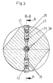
Im Schnittbild nach Fig. 4 werden ergänzend das doppelwandige
Zylinderrohr 3 mit seinen Kanälen 4 sowie die Gewindespindel
9 mit Axialbohrung 21 und den mit dieser verbundenen
Radialbohrungen 22 dargestellt.4 are the double-
Das mechanisch wirkende Sperrsystem in einem doppelt wirkenden
Arbeitszylinder 1 liegt in dessen Hauptachse 2, wobei
die autarke Steuerung im Bodenteil 23 angeordnet ist
und nur durch den Druck des Zu- und Abstroms des Fluids zum
normalen Betrieb betätigt wird. Es besteht im Wesentlichen
aus einer Gewindespindel 9, einer axial verschiebbaren
Sperrscheibe 11 mit einem ersten Zahnkranz 12, die auf dem
Vierkant 10 verdrehsicher, formschlüssig gelagert ist und
einer festen Sperrscheibe 18 mit einem zweiten Zahnkranz
17. Bei drucklosem Arbeitszylinder 1 sind die Verzahnungen
des ersten Zahnkranz 12 der verschiebbaren Sperrscheibe 11
und die des zweiten Zahnkranz 17 der festen Sperrscheibe 18
im Eingriff, formschlüssig gekoppelt, wobei die verschiebbare
Sperrscheibe 11 mittels der Sperrfeder 13 in diese
Sperrposition auf dem Vierkant 10 verschoben wurde.The mechanical locking system in one double acting
Working cylinder 1 lies in its
Die verschiebbare Sperrscheibe 11 und die feste Sperrscheibe
18 mit den Zahnkränzen 12; 17, die Paarung des Gewindes
der Gewindespindel 9 mit dem Innengewinde 7 des Kolbens 6
und die Sperrfeder 13 sind die entscheidenden Funktionselemente
des mechanischen Sperrsystems, wobei der rastende,
formschlüssige Eingriff der Verzahnungen der beiden Zahnkränze
12; 17 als Formgehemme arbeitet. Es ist so bemessen,
dass es gegen die Wirkung des Rückdrehmoments, welches über
die Kopplung des Innengewindes 7 des Kolbens 6 mit der Gewindespindel
9 durch äussere Kräfte auf die Kolbenstange 8
entsteht, eine ausreichende Rastgüte gewährleistet. Die feste
Sperrscheibe 18 ist in bekannter Weise mit dem Bodenteil
23 lösbar, jedoch kraft- und formschlüssig verbunden.
Am Außenmantel des Bodenteils 23 können an geeigneter Stelle
Abflachungen eingearbeitet sein, die für eine verdrehsichere
äussere Kopplung des Arbeitszylinders 1 sorgen, wenn
grössere Rückdrehmomente sicher aufzunehmen sind. Kleinere
Rückdrehmomente können über die Achse des Arbeitszylinders
1 geführt werden, um ein Gegenmoment über eine mit der Kolbenstange
8 verbundene Steckachsenlagerung zu erzeugen. The sliding
Die Funktion des Systems zur mechanischen Wegsperrung des Arbeitszylinders 1 wird nachfolgend an zwei wesentlichen Funktionszuständen näher erläutert.The function of the system for mechanically blocking the Working cylinder 1 will follow two essential Functional states explained in more detail.
Zustand 1 - das gesperrte System soll bei einzufahrender
Kolbenstange 8 durch den Zustrom eines unter Druck stehenden
Fluids entriegelt werden.State 1 - the locked system should be retracted
Über den Zuflussanschluss 24 wird das unter Druck stehende
Fluid eingeleitet und gelangt über die obere Leitung 25 in
die innere Ringkammer 26, aus der es weiter über die obere
Verbindungsleitung 27 in den oberen Rückschlagventilraum 28
gelangt, der den Abstrom in das obere Sperrrohr 41 ermöglicht.
Nach Fig. 1 und Fig. 2 weisen die Sperrrohre 41; 42
an ihrem linken Ende jeweils ein Vorspannventil 55 (55.1;
55.2) auf. Den Sperrrohren 41; 42 sind die Rückschlagventile
43.1; 43.2 antiparallel geschaltet, um den Rückfluss aus
dem jeweils ablauforientierten Kolbenstangenraum 48 oder
Kolbenraum 50 zu ermöglichen. Die Vorspannung der Vorspannventile
55.1; 55.2 ist so bemessen, dass die Gewähr dafür
gegeben ist, dass der Mittelschieber 36, der im drucklosen
Zustand über die Federn 37 in einer definierten Mittellage
gehalten wird, bei einzufahrender Kolbenstange 8 in seine
rechte Endlage gedrückt wird, bevor das Vorspannventil 55.1
das Fluid über die Leitung 47.1, die Kanäle 4 und die Radialnut
5 in den Kolbenstangenraum 48 abströmen lässt. In
der rechten Endlage des Mittelschiebers 36 sind dessen
Rückströmkanäle 38 so verschoben, dass der Entriegelungskolben
15 druckstabil mit dem Fluid beaufschlagt werden
kann.The
Nachdem der Mittelschieber 36 seine rechte Endlage erreicht
hat, strömt das über den oberen Verbindungskanal 51 und
durch das weitere vorgespannte Rückschlagventil 52 in den
Entriegelungskolbenraum 40, wodurch der Entriegelungskolben
15 axial, gegen die Wirkung der Vorspannung der Sperrfeder
13 über die verschiebbare Sperrscheibe 11 und die Stössel
16.1; 16.2, verschoben wird. Der Entriegelungskolben 15
verschiebt über die Stössel 16.1; 16.2 die verschiebbare
Sperrscheibe 11 axial auf dem Vierkant 10 der Gewindespindel
9, wodurch der Eingriff - die formschlüssige Kopplung
der Verzahnungen des ersten Zahnkranz 12 und des zweiten
Zahnkranz 17 aufgehoben werden, der Sperrzustand aufgehoben
ist. Der erforderliche Druck des Fluids , um den Sperrzustand
mittels des Verschiebens des Entriegelungskolbens 15
aufzuheben ist in seinem Wert um mindestens 10% Prozent höher
als der zum Verschieben des Mittelschiebers 36 benötigte
Druck. Erst nach dem Verschieben des Entriegelungskolbens
15, der damit erzielten Entsperrung, und einer weiteren
Druckerhöhung um mindestens weitere 10% gegenüber dem
Druck zum Verschieben des Entriegelungskolbens 15, öffnet
sich das Vorspannventil 55.1 des oberen Sperrrohrs 41, der
Abstrom des Fluids zum Kolbenstangenraum 48 erfolgt.After the
Mit der dann möglichen und erfolgenden Verschiebung des
Kolbens 6, der über sein Innengewinde 7 mit dem Gewinde der
Gewindespindel 9 in formschlüssiger Kopplung steht, ergibt
sich deren rotierende Bewegung und damit auch der über den
Vierkant 10 formschlüssig gekoppelten verschiebbaren Sperrscheibe
11. Die Bewegung des Kolbens 6 und der mit diesem
gekoppelten Kolbenstange 8 bewirkt stets eine Rotation der
Gewindespindel 9 und der mit dieser gekoppelten Elemente.With the then possible and successful postponement of
Piston 6, which has its
Das während der einfahrenden Bewegung der Kolbenstange 8
aus dem Kolbenraum 50 abzuführende Fluid strömt über die
weitere Leitung 49 durch das Rückschlagventil 43.2, die
Ringkammer 44 und die Bohrung 45.2 in das ölrückführende
Sperrrohr 42 sowie weiter über das ölrückführende Ventil
mit Ventilraum 35, die Leitung 34, den äusseren Ringkanal
33, die untere Verbindungsleitung 32 zum Abflussanschluss
30.That during the retracting movement of the
Zustand 2 - das entsperrte System soll bei einfahrender
Kolbenstange 8 durch einen plötzlichen Abfall des Drucks
des Fluids, beispielsweise Havarie der Druckleitung, sofort
verriegelt werden, um die Absenkung der äußeren Last zu
verhindern.State 2 - the unlocked system should enter
Infolge des fehlenden Drucks im Arbeitszylinder 1 wird der
Mittelschieber 36 durch die Federn 37 in die Mittellage
verschoben, wobei die Rückströmkanäle 38 über die Rückströmbohrung
39 mit dem Entriegelungskolbenraum 40 in abflussorientierte
Deckung gebracht werden und das Fluid vom
Entriegelungskolben 15, der durch die Vorspannung der
Sperrfeder 13 über die verschiebbare Sperrscheibe 11 und
die Stößel 16 (16.1: 16.2) zurückgedrückt wird, aus dem
Entriegelungskolbenraum 40 gedrückt wird.Due to the lack of pressure in the working cylinder 1, the
Gleichzeitig wird bewirkt, dass die Verzahnungen der Zahnkränze
12; 17 der Sperrscheiben 11, 18 wieder in Eingriff
kommen und die verdrehsichere Kopplung durch Formschluss
hergestellt ist. Die Größe der Kraft der Sperrfeder 13 ist
so bemessen, dass das infolge der Wirkung einer äußeren
Last auf die Kolbenstange 8 über die rotierende Gewindespindel
9 eingebrachte Rückdrehmoment verdrehsicher gehalten
wird.At the same time it causes the toothing of the ring gears
12; 17 of the locking
Lecköl aus dem Hubraum 14 sowie dem Bereich der Sperrfeder
13 werden bei jedem Hub des Entriegelungskolbens 15 in bekannter
Weise über das Rückschlagventil 20 in den Kolbenraum
50 abgeführt.Leakage oil from the displacement 14 and the area of the locking
In der praktischen Ausführung des beschriebenen Arbeitszylinders
1 wird die Gewindespindel 9 wie technisch üblich
von einem Gleitlager aufgenommen und mittels Anlaufscheibe
und Sicherungsring gehalten. In the practical version of the working cylinder described
1 is the threaded
- 11
- Arbeitszylinderworking cylinder
- 22
- Hauptachsemain axis
- 33
- doppelwandiges Zylinderrohrdouble-walled cylinder tube
- 44
- Kanälechannels
- 55
- Radialnutradial groove
- 66
- Kolbenpiston
- 77
- Innengewindeinner thread
- 88th
- Kolbenstangepiston rod
- 99
- Gewindespindelscrew
- 1010
- Vierkantsquare
- 1111
- verschiebbare Sperrscheibesliding lock washer
- 1212
- erster Zahnkranzfirst ring gear
- 1313
- Sperrfederlocking spring
- 1414
- Hubraumcapacity
- 1515
- Entriegelungskolbenunlocking
- 1616
- Stößel (16.1; 16.2)Plunger (16.1; 16.2)
- 1717
- zweiter Zahnkranzsecond ring gear
- 1818
- feste Sperrscheibefixed lock washer
- 1919
- Bohrungdrilling
- 2020
- Rückschlagventilcheck valve
- 2121
- Axialbohrungaxial bore
- 2222
- Radialbohrungenradial bores
- 2323
- Bodenteilthe bottom part
- 2424
- Zuflussanschlussinlet connection
- 2525
- obere Leitungtop line
- 2626
- innere Ringkammerinner annulus
- 2727
- obere Verbindungsleitungupper connecting line
- 2828
- oberer Rückschlagventilraumupper check valve space
- 2929
- oberes Rückschlagventilupper check valve
- 3030
- Abflussanschlussoutflow
- 3131
- Raumroom
- 3232
- untere Verbindungsleitung lower connecting line
- 33 ,33,
- äußerer Ringkanalouter ring channel
- 3434
- Leitungmanagement
- 3535
- ölrücklaufführendes Ventil mit Ventilraumoil return valve with valve chamber
- 3636
- Mittelschiebermeans slide
- 3737
- Federnfeathers
- 3838
- Rückströmkanälereturn flow
- 3939
- RückströmbohrungRückströmbohrung
- 4040
- EntriegelungskolbenraumEntriegelungskolbenraum
- 4141
- oberes Sperrrohrupper locking tube
- 4242
- ölrücklaufführendes Sperrrohroil returning locking tube
- 4343
- Rückschlagventil (43.1; 43.2)Check valve (43.1; 43.2)
- 4444
- Ringkammerannular chamber
- 4545
- Bohrung (45.1; 45.2)Bore (45.1; 45.2)
- 4646
- linke Ringkammerleft ring chamber
- 4747
- Leitungen (47.1; 47.2)Lines (47.1; 47.2)
- 4848
- KolbenstangenraumPiston rod space
- 4949
- weitere Leitungfurther management
- 5050
- Kolbenraumpiston chamber
- 5151
- oberer Verbindungskanalupper connection channel
- 5252
- weiteres vorgespanntes Rückschlagventilanother preloaded check valve
- 5353
- unterer Verbindungskanallower connection channel
- 5454
- zusätzliches vorgespanntes Rückschlagventiladditional preloaded check valve
- 5555
- Vorspannventil (55.1; 55.2)Preload valve (55.1; 55.2)
Claims (4)
- Pressure medium-operated working cylinder (1) having integrated, pressure-dependent mechanical locking of the translatory movement of a piston rod (8), having a control device for supplying and draining a pressure medium, a double-walled cylinder pipe (3), a base part (23) with a fixed locking disc (18), a piston rod guide, a partially hollow piston rod (8) on a bored-through piston (6) with an internal thread (7) which is operatively connected to the thread of a threaded spindle (9) which, at the lower end, has a coupling profile on which a locking disc (11) is axially displaceably mounted in a form-fit manner, which locking disc is coupled in the unpressurised state to the fixed locking disc (18) in the base part (23) of the working cylinder (1) by means of resilient pretensioning,
characterised in that
the locking disc (11) is coupled in a form-fit manner by a first toothed ring (12) to a second toothed ring (17) of the fixed locking disc (18) and
in the base part (23) a control device for the form-fit coupling of the two toothed rings (12; 17) of the locking discs (11; 18) is disposed, which control device is dependent upon the pressure of the fluid for operating the working cylinder (1), operates without additional external control elements and has no separate pressure medium connection and in that force-free unlocking is effected by an unlocking piston (15) by means of pretensioning valves (55) and a central slide valve (36), and the piston rod chamber (48) or piston chamber (50) are each subjected to the pressure fluid only after the locking system has been unlocked by this fluid. - Working cylinder as claimed in claim 1, characterised in that the thread pairing between the internal thread (7) of the piston (6) and the thread of the threaded spindle (9) consists of a non-self-locking thread with a steep pitch.
- Working cylinder as claimed in claims 1 or 2, characterised in that coupling is effected between the displaceable locking disc (11) and the fixed locking disc (18) by means of friction linings.
- Working cylinder as claimed in claims 1 to 3, characterised in that a swept volume (14) of an unlocking piston (15) is kept free of oil by its displacement effect during unlocking.
Applications Claiming Priority (2)
| Application Number | Priority Date | Filing Date | Title |
|---|---|---|---|
| DE20011789U DE20011789U1 (en) | 2000-07-06 | 2000-07-06 | Pressurized cylinder with mechanical travel lock in the depressurized state |
| DE20011789U | 2000-07-06 |
Publications (2)
| Publication Number | Publication Date |
|---|---|
| EP1170512A1 EP1170512A1 (en) | 2002-01-09 |
| EP1170512B1 true EP1170512B1 (en) | 2004-01-21 |
Family
ID=7943648
Family Applications (1)
| Application Number | Title | Priority Date | Filing Date |
|---|---|---|---|
| EP01114451A Expired - Lifetime EP1170512B1 (en) | 2000-07-06 | 2001-06-15 | Fluid pressure actuator with mechanical locking device when unpressurized |
Country Status (3)
| Country | Link |
|---|---|
| EP (1) | EP1170512B1 (en) |
| AT (1) | ATE258275T1 (en) |
| DE (2) | DE20011789U1 (en) |
Cited By (1)
| Publication number | Priority date | Publication date | Assignee | Title |
|---|---|---|---|---|
| DE102006030617B4 (en) * | 2005-12-29 | 2009-09-10 | Bümach Engineering International B.V. | Pressure-medium-operated working cylinder with mechanical path blocking in the unpressurized state |
Families Citing this family (5)
| Publication number | Priority date | Publication date | Assignee | Title |
|---|---|---|---|---|
| ITTO20011066A1 (en) * | 2001-11-13 | 2002-02-13 | Rolfo Spa | LINEAR ACTUATOR WITH INTERNAL MECHANICAL LOCKING. |
| DE20216197U1 (en) * | 2002-10-22 | 2004-03-04 | Bümach Engineering International B.V. | Hydraulic working cylinder |
| DE102004022203B3 (en) * | 2004-05-05 | 2005-08-11 | Neumeister Hydraulik Gmbh | Locking cylinder for ramps for low bed trucks has units for disengaging a plunger thread and a spindle thread so that axial movement of the plunger about the rotary axis is possible relative to the cylinder without rotating the spindle |
| DE202004009302U1 (en) | 2004-06-11 | 2004-08-26 | Bümach Engineering International B.V. | Pressurized cylinder with mechanical travel lock in the depressurized state |
| DE202005020365U1 (en) | 2005-12-29 | 2006-02-23 | Bümach Engineering International B.V. | Pressure-medium-operated working cylinder with mechanical path blocking in the unpressurized state |
Family Cites Families (9)
| Publication number | Priority date | Publication date | Assignee | Title |
|---|---|---|---|---|
| GB683633A (en) * | 1949-02-25 | 1952-12-03 | Gen Motors Corp | Improved fluid-pressure actuator |
| GB725003A (en) * | 1952-03-27 | 1955-03-02 | Gen Motors Corp | Improved fluid-pressure actuator |
| US2804053A (en) * | 1954-04-14 | 1957-08-27 | Gen Motors Corp | Actuator and locking means therefor |
| US2879746A (en) * | 1955-12-08 | 1959-03-31 | Gen Motors Corp | Actuator with unidirectional locking means |
| US3442176A (en) * | 1967-05-01 | 1969-05-06 | Gen Electric | Actuator locking mechanism |
| IT1271509B (en) * | 1993-10-06 | 1997-05-30 | Luciano Migliori | LINEAR PNEUMATIC ACTUATOR WITH REVERSIBLE ACTION BRAKE |
| JPH08303410A (en) * | 1995-04-27 | 1996-11-19 | Hino Motors Ltd | Fluid pressure cylinder |
| DE29720838U1 (en) * | 1997-11-25 | 1998-02-26 | Andexser Lucie | Working cylinder with integrated lifting brake |
| AT4094U1 (en) * | 1999-12-07 | 2001-01-25 | Weber Hydraulik Gmbh | LINEAR ACTUATOR |
-
2000
- 2000-07-06 DE DE20011789U patent/DE20011789U1/en not_active Expired - Lifetime
-
2001
- 2001-06-15 AT AT01114451T patent/ATE258275T1/en not_active IP Right Cessation
- 2001-06-15 EP EP01114451A patent/EP1170512B1/en not_active Expired - Lifetime
- 2001-06-15 DE DE50101349T patent/DE50101349D1/en not_active Expired - Fee Related
Cited By (1)
| Publication number | Priority date | Publication date | Assignee | Title |
|---|---|---|---|---|
| DE102006030617B4 (en) * | 2005-12-29 | 2009-09-10 | Bümach Engineering International B.V. | Pressure-medium-operated working cylinder with mechanical path blocking in the unpressurized state |
Also Published As
| Publication number | Publication date |
|---|---|
| DE50101349D1 (en) | 2004-02-26 |
| EP1170512A1 (en) | 2002-01-09 |
| ATE258275T1 (en) | 2004-02-15 |
| DE20011789U1 (en) | 2000-12-21 |
Similar Documents
| Publication | Publication Date | Title |
|---|---|---|
| EP1995471B1 (en) | Locking cylinder with fluid bearing | |
| EP2570679B1 (en) | Cylinder piston unit with locking means and correspondind methods for locking and unlocking | |
| EP1776527B1 (en) | Locking mechanism for linear actuators | |
| EP1170512B1 (en) | Fluid pressure actuator with mechanical locking device when unpressurized | |
| EP3101283B1 (en) | Double acting locking cylinder and method for operating a double acting locking cylinder | |
| EP2039944B1 (en) | Linear actuator, in particular cylinder-piston unit with locking device | |
| EP0505349B2 (en) | Hydraulic actuator | |
| EP1605171B1 (en) | Fluid pressure-actuated cylinder with mechanical locking | |
| DE10356598B3 (en) | Locking cylinder for hydraulically actuated component has spindle axially movable relative to cylinder and fixed to support body | |
| DE10356596B3 (en) | Locking cylinder for hydraulic system has load-holding descent brake devices connected to two working chambers | |
| DE102016119251A1 (en) | Hydromechanical locking cylinder and hydraulic control system for its operation | |
| DE3718246C1 (en) | Stroke limiting device for the pressure piston for the friction clutch in a clutch screw press | |
| EP0457030A1 (en) | Spring brake cylinder for compressed air operated vehicle brakes | |
| DE10356597B3 (en) | Locking cylinder unit for hydraulically actuated component has several locking bodies in form of separately movable locking bolts | |
| DE202005020365U1 (en) | Pressure-medium-operated working cylinder with mechanical path blocking in the unpressurized state | |
| EP2628960B1 (en) | Hydraulic non-return valve | |
| DE4224247C1 (en) | Shut=off slider with two=part shut=off plate insertable between two sealing seats - has ventilation elements each with two independently operating pressurised medium circuits used to raise plate parts from seats | |
| DE2041390C3 (en) | Double-acting working cylinder | |
| DE102006030617B4 (en) | Pressure-medium-operated working cylinder with mechanical path blocking in the unpressurized state | |
| DE1169780B (en) | Hydraulic adjusting cylinder with locking device | |
| EP1517049A2 (en) | Lockable pneumatic cylinder | |
| DE2945221A1 (en) | Remote-controlled ram assembly - has piston held by spring loaded locking member released by second piston | |
| DE1074361B (en) | Self-locking clamping devices for machine tools, in particular for lathes |
Legal Events
| Date | Code | Title | Description |
|---|---|---|---|
| PUAI | Public reference made under article 153(3) epc to a published international application that has entered the european phase |
Free format text: ORIGINAL CODE: 0009012 |
|
| 17P | Request for examination filed |
Effective date: 20010615 |
|
| AK | Designated contracting states |
Kind code of ref document: A1 Designated state(s): AT BE CH CY DE DK ES FI FR GB GR IE IT LI LU MC NL PT SE TR Kind code of ref document: A1 Designated state(s): AT DE FR GB IT NL |
|
| AX | Request for extension of the european patent |
Free format text: AL;LT;LV;MK;RO;SI |
|
| GBC | Gb: translation of claims filed (gb section 78(7)/1977) | ||
| EL | Fr: translation of claims filed | ||
| TCNL | Nl: translation of patent claims filed | ||
| AKX | Designation fees paid |
Free format text: AT DE FR GB IT NL |
|
| 17Q | First examination report despatched |
Effective date: 20030204 |
|
| GRAP | Despatch of communication of intention to grant a patent |
Free format text: ORIGINAL CODE: EPIDOSNIGR1 |
|
| GRAS | Grant fee paid |
Free format text: ORIGINAL CODE: EPIDOSNIGR3 |
|
| GRAA | (expected) grant |
Free format text: ORIGINAL CODE: 0009210 |
|
| AK | Designated contracting states |
Kind code of ref document: B1 Designated state(s): AT DE FR GB IT NL |
|
| REG | Reference to a national code |
Ref country code: GB Ref legal event code: FG4D Free format text: NOT ENGLISH |
|
| GBT | Gb: translation of ep patent filed (gb section 77(6)(a)/1977) |
Effective date: 20040121 |
|
| REG | Reference to a national code |
Ref country code: IE Ref legal event code: FG4D Free format text: GERMAN |
|
| REF | Corresponds to: |
Ref document number: 50101349 Country of ref document: DE Date of ref document: 20040226 Kind code of ref document: P |
|
| REG | Reference to a national code |
Ref country code: IE Ref legal event code: FD4D |
|
| ET | Fr: translation filed | ||
| PLBE | No opposition filed within time limit |
Free format text: ORIGINAL CODE: 0009261 |
|
| STAA | Information on the status of an ep patent application or granted ep patent |
Free format text: STATUS: NO OPPOSITION FILED WITHIN TIME LIMIT |
|
| 26N | No opposition filed |
Effective date: 20041022 |
|
| PGFP | Annual fee paid to national office [announced via postgrant information from national office to epo] |
Ref country code: NL Payment date: 20090630 Year of fee payment: 9 |
|
| PGFP | Annual fee paid to national office [announced via postgrant information from national office to epo] |
Ref country code: AT Payment date: 20090615 Year of fee payment: 9 Ref country code: IT Payment date: 20090617 Year of fee payment: 9 |
|
| PGFP | Annual fee paid to national office [announced via postgrant information from national office to epo] |
Ref country code: FR Payment date: 20090625 Year of fee payment: 9 |
|
| PGFP | Annual fee paid to national office [announced via postgrant information from national office to epo] |
Ref country code: DE Payment date: 20090630 Year of fee payment: 9 Ref country code: GB Payment date: 20090610 Year of fee payment: 9 |
|
| REG | Reference to a national code |
Ref country code: NL Ref legal event code: V1 Effective date: 20110101 |
|
| GBPC | Gb: european patent ceased through non-payment of renewal fee |
Effective date: 20100615 |
|
| REG | Reference to a national code |
Ref country code: FR Ref legal event code: ST Effective date: 20110228 |
|
| PG25 | Lapsed in a contracting state [announced via postgrant information from national office to epo] |
Ref country code: IT Free format text: LAPSE BECAUSE OF NON-PAYMENT OF DUE FEES Effective date: 20100615 |
|
| PG25 | Lapsed in a contracting state [announced via postgrant information from national office to epo] |
Ref country code: DE Free format text: LAPSE BECAUSE OF NON-PAYMENT OF DUE FEES Effective date: 20110101 |
|
| PG25 | Lapsed in a contracting state [announced via postgrant information from national office to epo] |
Ref country code: FR Free format text: LAPSE BECAUSE OF NON-PAYMENT OF DUE FEES Effective date: 20100630 Ref country code: NL Free format text: LAPSE BECAUSE OF NON-PAYMENT OF DUE FEES Effective date: 20110101 Ref country code: AT Free format text: LAPSE BECAUSE OF NON-PAYMENT OF DUE FEES Effective date: 20100615 |
|
| PG25 | Lapsed in a contracting state [announced via postgrant information from national office to epo] |
Ref country code: GB Free format text: LAPSE BECAUSE OF NON-PAYMENT OF DUE FEES Effective date: 20100615 |