EP1170436A1 - Greenhouse awning - Google Patents
Greenhouse awning Download PDFInfo
- Publication number
- EP1170436A1 EP1170436A1 EP01108101A EP01108101A EP1170436A1 EP 1170436 A1 EP1170436 A1 EP 1170436A1 EP 01108101 A EP01108101 A EP 01108101A EP 01108101 A EP01108101 A EP 01108101A EP 1170436 A1 EP1170436 A1 EP 1170436A1
- Authority
- EP
- European Patent Office
- Prior art keywords
- awning
- push
- conservatory
- fabric
- bands
- Prior art date
- Legal status (The legal status is an assumption and is not a legal conclusion. Google has not performed a legal analysis and makes no representation as to the accuracy of the status listed.)
- Granted
Links
Images
Classifications
-
- E—FIXED CONSTRUCTIONS
- E04—BUILDING
- E04F—FINISHING WORK ON BUILDINGS, e.g. STAIRS, FLOORS
- E04F10/00—Sunshades, e.g. Florentine blinds or jalousies; Outside screens; Awnings or baldachins
- E04F10/02—Sunshades, e.g. Florentine blinds or jalousies; Outside screens; Awnings or baldachins of flexible canopy materials, e.g. canvas ; Baldachins
- E04F10/06—Sunshades, e.g. Florentine blinds or jalousies; Outside screens; Awnings or baldachins of flexible canopy materials, e.g. canvas ; Baldachins comprising a roller-blind with means for holding the end away from a building
- E04F10/0685—Covers or housings for the rolled-up blind
-
- E—FIXED CONSTRUCTIONS
- E04—BUILDING
- E04F—FINISHING WORK ON BUILDINGS, e.g. STAIRS, FLOORS
- E04F10/00—Sunshades, e.g. Florentine blinds or jalousies; Outside screens; Awnings or baldachins
- E04F10/02—Sunshades, e.g. Florentine blinds or jalousies; Outside screens; Awnings or baldachins of flexible canopy materials, e.g. canvas ; Baldachins
- E04F10/06—Sunshades, e.g. Florentine blinds or jalousies; Outside screens; Awnings or baldachins of flexible canopy materials, e.g. canvas ; Baldachins comprising a roller-blind with means for holding the end away from a building
- E04F10/0607—Sunshades, e.g. Florentine blinds or jalousies; Outside screens; Awnings or baldachins of flexible canopy materials, e.g. canvas ; Baldachins comprising a roller-blind with means for holding the end away from a building with guiding-sections for supporting the movable end of the blind
-
- E—FIXED CONSTRUCTIONS
- E04—BUILDING
- E04F—FINISHING WORK ON BUILDINGS, e.g. STAIRS, FLOORS
- E04F10/00—Sunshades, e.g. Florentine blinds or jalousies; Outside screens; Awnings or baldachins
- E04F10/02—Sunshades, e.g. Florentine blinds or jalousies; Outside screens; Awnings or baldachins of flexible canopy materials, e.g. canvas ; Baldachins
- E04F10/06—Sunshades, e.g. Florentine blinds or jalousies; Outside screens; Awnings or baldachins of flexible canopy materials, e.g. canvas ; Baldachins comprising a roller-blind with means for holding the end away from a building
- E04F10/0644—Sunshades, e.g. Florentine blinds or jalousies; Outside screens; Awnings or baldachins of flexible canopy materials, e.g. canvas ; Baldachins comprising a roller-blind with means for holding the end away from a building with mechanisms for unrolling or balancing the blind
- E04F10/0648—Sunshades, e.g. Florentine blinds or jalousies; Outside screens; Awnings or baldachins of flexible canopy materials, e.g. canvas ; Baldachins comprising a roller-blind with means for holding the end away from a building with mechanisms for unrolling or balancing the blind acting on the roller tube
Definitions
- the invention relates to a conservatory awning comprising a Fabric shaft for winding up an awning fabric to form a Cloth wraps and side guide rails for guiding the awning cloth when extending.
- Such conservatory awnings are used to shade conservatories or parts of buildings with larger glass sections.
- Such awnings with rail-guided counter-pull systems are traditional equipped, d. H. one arranged at the front end of the awning fabric Failure rail is pulled.
- commercially available Articulated arm awnings used.
- the object of the invention is a conservatory awning of the generic type so that the disadvantages conventional awnings avoided and the design options be expanded.
- the push bands made of stainless steel, carbon composite material or the like. she can be connected to the awning fabric over a wide area or at certain points.
- the push bands are preferably in rails or rail sections guided, which the push bands favorably form-fitting issue.
- the push bands advantageously have a thickness corresponding approximately to that Thickness of the awning cover.
- the push bands can be rows of holes, punched or toothed Intervention of corresponding drive, guidance and / or stabilization means exhibit.
- These devices can be spring-loaded by spring-loaded pressure rollers mounted pressure sliding jaws or spring-loaded, the winding surrounding flange half-shells can be formed.
- a strap be provided, which extends around the push band winding and is spring loaded, especially in the tangential direction.
- the Push bands have a curvature around their longitudinal axis and possibly also be guided in a correspondingly curved guide rail.
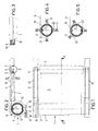
- a conservatory awning 1 shown in the drawing comprises an awning cloth 2, which on a cloth shaft 3 to form a Cloth roll 4 is wound.
- the front end 5 of the awning fabric 2 is over a piping 6 and one Keder groove 7 connected to a drop rail 3.
- the drop rail 3 is laterally each with an L-shaped slider 8 provided, which in turn with a slightly curved around the longitudinal axis, Connected to the drop rail 3 extending push band 9 is, slider 8 and push belt 9 in one of a total of two guide rails 10 are slidably guided. This will make the required stiffening of the push belt 9 guaranteed in the push direction.
- the push belt 10 forms its own winding 19, which in the embodiment 1 to 3 is guided by a clamp guide 11, the comprises two half-shells 12, 13 surrounding the winding, which Have flange lugs 14, 15 through which a screw 16 extends, being between the screw head 17 of the screw 16 and the flange 14 a coil spring 18 is arranged, which ensures that the half-shells 12, 13 towards each other and against the push band winding 19 always are subjected to force, so that a uniform extension of the push belt 9 is guaranteed.
- the drive thrust is transmitted via the drive when extending the cloth shaft, which apply the push bands 9 to thrust, so that accordingly, in contrast to the prior art, not with Tension bands or the like is worked.
- a tension band 23 is provided, which extends around the push band winding 19.
- On first end 24 of the tensioning band 23 is provided with a piping 25 which is in a keder groove 26 is fixed.
- the other end 27 is over a hook 28 connected to an approximately tangentially arranged coil spring, the other end of the coil spring 29 being fixed by a hook 30 is.
Abstract
Description
Die Erfindung richtet sich auf eine Wintergartenmarkise umfassend eine Tuchwelle zum Aufwickeln eines Markisentuches unter Ausbildung eines Tuchwickels und seitliche Führungsschienen zum Führen des Markisentuches beim Ausfahren.The invention relates to a conservatory awning comprising a Fabric shaft for winding up an awning fabric to form a Cloth wraps and side guide rails for guiding the awning cloth when extending.
Solche Wintergartenmarkisen dienen zur Beschattung von Wintergärten oder Gebäudeteilen mit größeren Glasabschnitten.Such conservatory awnings are used to shade conservatories or parts of buildings with larger glass sections.
Herkömmlicherweise sind solche Markisen mit schienengeführten Gegenzugsystemen ausgestattet, d. h. eine am Vorderende des Markisentuchs angeordnete Ausfallschiene wird gezogen. Alternativ werden handelsübliche Gelenkarmmarkisen eingesetzt.Such awnings with rail-guided counter-pull systems are traditional equipped, d. H. one arranged at the front end of the awning fabric Failure rail is pulled. Alternatively, commercially available Articulated arm awnings used.
Die bekannten Zugsysteme weisen den Nachteil auf, daß eine Längendifferenz zwischen Abwickel-Umfang und Aufwickel-Umfang durch eine Elastizität im Zugsystem überbrückt werden muß. Dies ist kostenaufwendig und begrenzt den maximalen Ausfall solcher Anordnungen.The known train systems have the disadvantage that there is a difference in length between the unwinding circumference and the winding circumference due to elasticity must be bridged in the train system. This is expensive and limits the maximum failure of such arrangements.
Hiervon ausgehend liegt der Erfindung die Aufgabe zugrunde, eine Wintergartenmarkise der gattungsgemäßen Art so auszugestalten, daß die Nachteile herkömmlicher Markisen vermieden und die Gestaltungsmöglichkeiten erweitert werden.Proceeding from this, the object of the invention is a conservatory awning of the generic type so that the disadvantages conventional awnings avoided and the design options be expanded.
Diese Aufgabe wird erfindungsgemäß dadurch gelöst, daß das Markisentuch zusammen mit diesem aufwickelbare, in Ausfahrrichtung eigensteife Schubbänder aufweist. Dementsprechend ist es möglich, über die antreibbare Tuchwelle das Ausfahren des Markisentuches ausschließlich über die Wirkung der Schubbänder zu bewerkstelligen. Mit einem solchen System werden die Nachteile herkömmlicher Zuganordnungen vermieden und es ist darüber hinaus möglich, große Ausfallweiten zu erreichen und gewölbte Schattiersysteme zu realisieren.This object is achieved in that the awning cloth together with this windable, inherently stiff in the direction of extension Has push bands. Accordingly, it is possible to use the drivable The shaft of the awning can only be extended using the Effect of the push bands. With such a system the disadvantages of conventional train arrangements are avoided and it is furthermore possible to achieve large failure distances and arched Realize shading systems.
In weiterer Ausgestaltung der Erfindung ist vorgesehen, daß die Schubbänder aus Edelstahl, Carbon-Verbundmaterial oder dergleichen bestehen. Sie können flächig oder punktuell mit dem Markisentuch verbunden sein.In a further embodiment of the invention it is provided that the push bands made of stainless steel, carbon composite material or the like. she can be connected to the awning fabric over a wide area or at certain points.
Die Schubbänder sind vorzugsweise in Schienen oder Schienenabschnitten geführt, welche den Schubbändern günstigerweise möglichst formschlüssig anliegen.The push bands are preferably in rails or rail sections guided, which the push bands favorably form-fitting issue.
Mit Vorteil weisen die Schubbänder eine Dicke entsprechend etwa der Dicke des Markisentuchs auf.The push bands advantageously have a thickness corresponding approximately to that Thickness of the awning cover.
Die Schubbänder können Lochreihen, Ausstanzungen oder Zahnungen zum Eingriff korrespondierender Antriebs-, Führungs- und/oder Stabilisierungsmittel aufweisen.The push bands can be rows of holes, punched or toothed Intervention of corresponding drive, guidance and / or stabilization means exhibit.
Bei einer bevorzugten Ausführungsform sind längs des Außenumfangs des Schubband-Wickels Einrichtungen zur radial nach innen gerichteten, federnden Kraftbeaufschlagung vorgesehen, um hierdurch den Wickel zu stabilisieren und eine gleichmäßige Ausschubbewegung zu erzielen.In a preferred embodiment, along the outer circumference of the Push band winding devices for radially inward, resilient The application of force is provided in order to thereby close the winding stabilize and achieve an even extension movement.
Diese Einrichtungen können durch federnd gelagerte Andrückrollen, federnd gelagerte Andruck-Gleitbacken oder federbeaufschlagte, den Wickel umgebende Flansch-Halbschalen gebildet sein. Alternativ kann ein Spannband vorgesehen sein, welches sich um den Schubband-Wickel herumerstreckt und federbeaufschlagt ist, insbesondere in tangentialer Richtung.These devices can be spring-loaded by spring-loaded pressure rollers mounted pressure sliding jaws or spring-loaded, the winding surrounding flange half-shells can be formed. Alternatively, a strap be provided, which extends around the push band winding and is spring loaded, especially in the tangential direction.
Zur Erzielung einer größeren Stabilisierung in Längsrichtung können die Schubbänder eine Wölbung um deren Längsachse aufweisen und ggf. auch in einer entsprechend gewölbten Führungsschiene geführt sein.To achieve greater stabilization in the longitudinal direction, the Push bands have a curvature around their longitudinal axis and possibly also be guided in a correspondingly curved guide rail.
Nachfolgend wird die Erfindung anhand eines bevorzugten Ausführungsbeispiels in Verbindung mit der Zeichnung näher beschrieben. Dabei zeigen:
- Fig. 1
- eine Aufsicht auf eine erfindungsgemäße Wintergartenmarkise,
- Fig. 2
- einen Schnitt durch die Wintergartenmarkise längs der Schnittlinie II-II in Fig. 1,
- Fig. 3
- einen Schnitt des Seitenbereichs längs der Schnittlinie III-III in Fig. 2,
- Fig. 4
- eine schematische Darstellung einer alternativen Ausführungsform der Andrückanordnung,
- Fig. 5
- eine Fig. 4 entsprechende Darstellung einer weiteren Ausführungsform, und
- Fig. 6
- eine Fig. 4 entsprechende Darstellung einer dritten Ausführungsform.
- Fig. 1
- a supervision of a conservatory awning according to the invention,
- Fig. 2
- 2 shows a section through the conservatory awning along the section line II-II in FIG. 1,
- Fig. 3
- 3 shows a section of the side region along the section line III-III in FIG. 2,
- Fig. 4
- 1 shows a schematic illustration of an alternative embodiment of the pressing arrangement,
- Fig. 5
- a representation corresponding to FIG. 4 of a further embodiment, and
- Fig. 6
- a representation corresponding to FIG. 4 of a third embodiment.
Eine in der Zeichnung dargestellte Wintergartenmarkise 1 umfaßt ein Markisentuch
2, welches auf eine Tuchwelle 3 unter Ausbildung eines
Tuchwickels 4 aufgewickelt ist.A
Das vordere Ende 5 des Markisentuchs 2 ist über einen Keder 6 und eine
Kedernut 7 mit einer Ausfallschiene 3 verbunden.The
Die Ausfallschiene 3 ist seitlich jeweils mit einem L-förmigen Gleitstück 8
versehen, welches seinerseits mit einem um die Längsachse leicht gewölbten,
senkrecht zur Ausfallschiene 3 verlaufenden Schubband 9 verbunden
ist, wobei Gleitstück 8 und Schubband 9 in einer von insgesamt zwei Führungsschienen
10 formschlüssig gleitend geführt sind. Hierdurch wird die
erforderliche Versteifung des Schubbandes 9 in Schubrichtung gewährleistet.The
Das Schubband 10 bildet einen eigenen Wickel 19, der bei der Ausführungsform
nach Fig. 1 bis 3 durch eine Klammerführung 11 geführt ist, die
zwei den Wickel umgebende Halbschalen 12, 13 umfaßt, welche
Flanschansätze 14, 15 aufweisen, durch die sich eine Schraube 16 erstreckt,
wobei zwischen dem Schraubenkopf 17 der Schraube 16 und dem Flansch
14 eine Schraubenfeder 18 angeordnet ist, die dafür sorgt, daß die Halbschalen
12, 13 aufeinander zu und gegen den Schubband-Wickel 19 stets
kraftbeaufschlagt sind, so daß ein gleichmäßiger Ausschub des Schubbandes
9 gewährleistet ist.The
Die Übertragung des Antriebsschubs beim Ausfahren erfolgt über den Antrieb
der Tuchwelle, die die Schubbänder 9 auf Schub beaufschlagen, so
daß dementsprechend, im Gegensatz zum Stand der Technik, nicht mit
Zugbändern oder dergleichen gearbeitet wird.The drive thrust is transmitted via the drive when extending
the cloth shaft, which apply the
Bei der Ausführungsform nach Fig. 4 wird der auf der Tuchwelle 3 aufgerollte
Schubband-Wickel 19 durch Andrückrollen 20, auf die Schraubenfedem
21 einwirken, radial nach innen beaufschlagt.In the embodiment according to FIG. 4, the one rolled up on the
Bei der Ausführungsform nach Fig. 5 sind statt der Andrückrollen 20
Gleitbacken 22 vorgesehen, welche sich abschnittsweise in Umfangsrichtung
um den Schubband-Wickel 19 herumerstrecken.In the embodiment according to FIG. 5, instead of the
Bei der in Fig. 6 dargestellten Ausführungsform ist ein Spannband 23 vorgesehen,
welches sich um den Schubband-Wickel 19 herumerstreckt. Ein
erstes Ende 24 des Spannbandes 23 ist mit einem Keder 25 versehen, der in
einer Kedernut 26 festgelegt ist. Das andere Ende 27 ist über einen Haken
28 mit einer annähernd tangential angeordneten Schraubenfeder verbunden,
wobei das andere Ende der Schraubenfeder 29 über einen Haken 30 festgelegt
ist.In the embodiment shown in FIG. 6, a
Claims (10)
dadurch gekennzeichnet, daß das Markisentuch (2) zusammen mit diesem aufwickelbare, in Ausfahrrichtung eigensteife Schubbänder (9) aufweist.Conservatory awning comprising a fabric shaft for winding up an awning fabric to form a fabric wrap and lateral guide rails for guiding the awning fabric when extending,
characterized in that the awning fabric (2), together with the latter, has push bands (9) which are inherently rigid in the extending direction.
Applications Claiming Priority (2)
| Application Number | Priority Date | Filing Date | Title |
|---|---|---|---|
| DE10033419 | 2000-07-08 | ||
| DE10033419A DE10033419A1 (en) | 2000-07-08 | 2000-07-08 | Conservatory awning |
Publications (2)
| Publication Number | Publication Date |
|---|---|
| EP1170436A1 true EP1170436A1 (en) | 2002-01-09 |
| EP1170436B1 EP1170436B1 (en) | 2004-11-10 |
Family
ID=7648375
Family Applications (1)
| Application Number | Title | Priority Date | Filing Date |
|---|---|---|---|
| EP01108101A Expired - Lifetime EP1170436B1 (en) | 2000-07-08 | 2001-03-30 | Greenhouse awning |
Country Status (6)
| Country | Link |
|---|---|
| US (1) | US6625936B2 (en) |
| EP (1) | EP1170436B1 (en) |
| JP (1) | JP2002070463A (en) |
| AT (1) | ATE282122T1 (en) |
| DE (2) | DE10033419A1 (en) |
| ES (1) | ES2232537T3 (en) |
Families Citing this family (14)
| Publication number | Priority date | Publication date | Assignee | Title |
|---|---|---|---|---|
| DE10132616A1 (en) * | 2001-07-05 | 2003-01-23 | Schmitz Werke | Conservatory awning or the like |
| DE10218572A1 (en) | 2002-04-26 | 2003-11-06 | Schmitz Werke | Awning, especially conservatory awning |
| US7108037B1 (en) | 2003-03-04 | 2006-09-19 | R.V. Specialties, Inc. | Lock mechanism for retractable awning |
| US7647128B2 (en) | 2005-04-22 | 2010-01-12 | Microsoft Corporation | Methods, computer-readable media, and data structures for building an authoritative database of digital audio identifier elements and identifying media items |
| DE102005048207B3 (en) * | 2005-10-07 | 2006-11-23 | Webasto Ag | Roller blind fitting for motor vehicle includes side winding guide in region of winding shaft for each guide band |
| KR100777325B1 (en) | 2007-07-23 | 2007-11-20 | 이형주 | Folding type awning |
| JP5162403B2 (en) * | 2008-10-02 | 2013-03-13 | 株式会社タカショー | Shade device |
| JP5243940B2 (en) * | 2008-12-17 | 2013-07-24 | 八千代工業株式会社 | Vehicle shade device |
| DE102010024999A1 (en) | 2010-06-24 | 2011-12-29 | Warema Renkhoff Se | Awning i.e. winter garden awning for shading transparent roof area of winter garden in hot summer, has hanging parts movable to different shading positions and reinforced with tapes, where tapes run in guide rails to transfer pushing force |
| CL2012002171U1 (en) * | 2012-08-03 | 2012-11-30 | Hunter Douglas Chile S A | A bankrupt formed by a structure that supports an interweave of metal sheets, consisting of structural profiles to support the sheets, where the sheets alternately pass through the front of an outer tube and through the back of an inner tube, the ends of the sheets have reinforcing plates and means for tensioning them |
| CN104120841B (en) * | 2013-04-28 | 2016-08-24 | 长春雷特科技有限公司 | A kind of luminous energy roof |
| USD735889S1 (en) | 2013-06-14 | 2015-08-04 | Schmitz-Werke Gmbh + Co. Kg | Awning holder |
| CN103337222B (en) * | 2013-07-01 | 2015-07-08 | 京东方科技集团股份有限公司 | Flexible display device |
| EP3250774B1 (en) * | 2015-01-28 | 2020-02-26 | Frinova GmbH | Door, in particular a high-speed door |
Citations (4)
| Publication number | Priority date | Publication date | Assignee | Title |
|---|---|---|---|---|
| FR2563555A1 (en) * | 1984-04-27 | 1985-10-31 | Pons Pierre | Tension device enabling a canopy-type blind to be wound and unwound |
| US5203393A (en) * | 1991-04-24 | 1993-04-20 | Blevins Timothy D | Awning support ribs |
| EP0682162A1 (en) * | 1994-05-10 | 1995-11-15 | CLAUSS MARKISEN PROJEKT GmbH | Awning |
| EP0778379A1 (en) * | 1995-12-08 | 1997-06-11 | CLAUSS MARKISEN PROJEKT GmbH | Awning with positive return with springs running along the same |
Family Cites Families (16)
| Publication number | Priority date | Publication date | Assignee | Title |
|---|---|---|---|---|
| US4576192A (en) * | 1983-01-24 | 1986-03-18 | Randall Equipment Company | Awning assembly |
| FR2558518A1 (en) * | 1984-01-20 | 1985-07-26 | Goidin Michel | Motorised blind with unrolling controlled by pulling cables |
| USD292874S (en) * | 1984-06-06 | 1987-11-24 | Ulrich Clauss | Rail assembly for awning or similar article |
| DE3601150A1 (en) * | 1986-01-16 | 1987-07-23 | Cassani Gmbh | Guide device for the front edge of an awning web |
| DE4011876A1 (en) * | 1990-04-12 | 1991-10-17 | Viktor Lohausen | JOINT ARM AWNINGS |
| DE4021264C2 (en) * | 1990-07-04 | 1994-07-07 | Clauss Markisen | Inclined awning |
| DE9300449U1 (en) * | 1993-01-15 | 1993-03-04 | Losberger Sonnenschutz Gmbh + Co, 7100 Heilbronn, De | |
| DE9309350U1 (en) * | 1993-06-23 | 1993-08-12 | Schmitz-Werke Gmbh + Co, 48282 Emsdetten, De | |
| US5873400A (en) * | 1996-11-27 | 1999-02-23 | Carefree/Scott Fetzer Company | Tie-down system for a retractable awning |
| US5752536A (en) * | 1997-03-06 | 1998-05-19 | White Consolidated Industries, Inc. | Locking mechanism for slide-out room cover |
| US6050280A (en) * | 1998-06-06 | 2000-04-18 | Jeske; Stewart Patrick | Sports shade |
| US6095221A (en) * | 1998-08-20 | 2000-08-01 | White Consolidated Industries, Inc. | Awning extension and retraction mechanism |
| US6273172B1 (en) * | 1998-08-20 | 2001-08-14 | White Consolidated Industries, Inc. | Motor operated awning |
| US6269824B1 (en) * | 2000-01-28 | 2001-08-07 | Louis Marcel Brutsaert | Slide-out |
| US6315025B1 (en) * | 2000-07-26 | 2001-11-13 | John J. Mabie | Removable awning cover |
| US6382293B1 (en) * | 2000-12-19 | 2002-05-07 | Camco Manufacturing, Inc. | Awning tension assembly and method |
-
2000
- 2000-07-08 DE DE10033419A patent/DE10033419A1/en not_active Withdrawn
-
2001
- 2001-03-30 EP EP01108101A patent/EP1170436B1/en not_active Expired - Lifetime
- 2001-03-30 DE DE50104458T patent/DE50104458D1/en not_active Expired - Fee Related
- 2001-03-30 ES ES01108101T patent/ES2232537T3/en not_active Expired - Lifetime
- 2001-03-30 AT AT01108101T patent/ATE282122T1/en not_active IP Right Cessation
- 2001-05-17 US US09/858,461 patent/US6625936B2/en not_active Expired - Fee Related
- 2001-05-17 JP JP2001147942A patent/JP2002070463A/en active Pending
Patent Citations (4)
| Publication number | Priority date | Publication date | Assignee | Title |
|---|---|---|---|---|
| FR2563555A1 (en) * | 1984-04-27 | 1985-10-31 | Pons Pierre | Tension device enabling a canopy-type blind to be wound and unwound |
| US5203393A (en) * | 1991-04-24 | 1993-04-20 | Blevins Timothy D | Awning support ribs |
| EP0682162A1 (en) * | 1994-05-10 | 1995-11-15 | CLAUSS MARKISEN PROJEKT GmbH | Awning |
| EP0778379A1 (en) * | 1995-12-08 | 1997-06-11 | CLAUSS MARKISEN PROJEKT GmbH | Awning with positive return with springs running along the same |
Also Published As
| Publication number | Publication date |
|---|---|
| ES2232537T3 (en) | 2005-06-01 |
| DE50104458D1 (en) | 2004-12-16 |
| EP1170436B1 (en) | 2004-11-10 |
| US20020002800A1 (en) | 2002-01-10 |
| US6625936B2 (en) | 2003-09-30 |
| JP2002070463A (en) | 2002-03-08 |
| DE10033419A1 (en) | 2002-01-17 |
| ATE282122T1 (en) | 2004-11-15 |
Similar Documents
| Publication | Publication Date | Title |
|---|---|---|
| EP1170436B1 (en) | Greenhouse awning | |
| EP0519241B1 (en) | Device for drawing the cloth of a blind in order to roll it up or down, as well as corresponding blind | |
| DE1781458C2 (en) | Roll winding made from a wire strand wound on a central drum and method for producing the roll winding | |
| EP1367207A2 (en) | Driving device, especially for a vehicle sliding roof, as well as vehicle sliding roof | |
| DE19807541C1 (en) | Tensioner for awning draw cable | |
| EP1273734B1 (en) | Greenhouse awning or the like | |
| EP0778379B1 (en) | Awning with positive return with springs running along the same | |
| DE4036892A1 (en) | Tension device for venetian blind or awning - has draw unit engaging with front edge of blind sheet | |
| DE2601589A1 (en) | RIBBON REEL | |
| DE4139312A1 (en) | COVER DEVICE | |
| EP0669447A1 (en) | Sun-protecting device | |
| DE7832604U1 (en) | SIDE GUIDE FOR ROLLER CURTAINS | |
| DE202013103538U1 (en) | Under the roof awning | |
| DE102009051344A1 (en) | foil-sheet | |
| EP3061887B1 (en) | Sun protection device | |
| EP3048213B1 (en) | Awning with tissue counter-movement system | |
| DE19814577C1 (en) | Sun-shade arrangement with length of canvas unrolled from shaft | |
| DE1205256B (en) | Extendable mast made of windable tapes | |
| DE19700757C2 (en) | Counter awning | |
| EP0559959A2 (en) | Tensioning mechanism for a flexible covering | |
| DE644678C (en) | Roof for motor vehicles | |
| DE102006045776A1 (en) | Fastening element for fastening a flexible strip of material on a tie with a free end, especially for fastening an energy or shading shield on a tie in a profiled guide section in a greenhouse has an outer shell and a barbed hook | |
| DE2904884A1 (en) | Variable length awning hinge arms - are guided in two or more tiered levels between rear tube and drop rod | |
| DE669934C (en) | Conveyor for binding mower or the like. | |
| DE2346572C3 (en) | Device for conveying and distributing hay and the like |
Legal Events
| Date | Code | Title | Description |
|---|---|---|---|
| PUAI | Public reference made under article 153(3) epc to a published international application that has entered the european phase |
Free format text: ORIGINAL CODE: 0009012 |
|
| 17P | Request for examination filed |
Effective date: 20011115 |
|
| AK | Designated contracting states |
Kind code of ref document: A1 Designated state(s): AT BE CH CY DE DK ES FI FR GB GR IE IT LI LU MC NL PT SE TR |
|
| AX | Request for extension of the european patent |
Free format text: AL;LT;LV;MK;RO;SI |
|
| AKX | Designation fees paid |
Free format text: AT BE CH CY DE DK ES FI FR GB GR IE IT LI LU MC NL PT SE TR |
|
| GRAP | Despatch of communication of intention to grant a patent |
Free format text: ORIGINAL CODE: EPIDOSNIGR1 |
|
| GRAS | Grant fee paid |
Free format text: ORIGINAL CODE: EPIDOSNIGR3 |
|
| GRAA | (expected) grant |
Free format text: ORIGINAL CODE: 0009210 |
|
| AK | Designated contracting states |
Kind code of ref document: B1 Designated state(s): AT BE CH CY DE DK ES FI FR GB GR IE IT LI LU MC NL PT SE TR |
|
| PG25 | Lapsed in a contracting state [announced via postgrant information from national office to epo] |
Ref country code: TR Free format text: LAPSE BECAUSE OF FAILURE TO SUBMIT A TRANSLATION OF THE DESCRIPTION OR TO PAY THE FEE WITHIN THE PRESCRIBED TIME-LIMIT Effective date: 20041110 Ref country code: IE Free format text: LAPSE BECAUSE OF FAILURE TO SUBMIT A TRANSLATION OF THE DESCRIPTION OR TO PAY THE FEE WITHIN THE PRESCRIBED TIME-LIMIT Effective date: 20041110 Ref country code: FI Free format text: LAPSE BECAUSE OF FAILURE TO SUBMIT A TRANSLATION OF THE DESCRIPTION OR TO PAY THE FEE WITHIN THE PRESCRIBED TIME-LIMIT Effective date: 20041110 |
|
| REG | Reference to a national code |
Ref country code: GB Ref legal event code: FG4D Free format text: NOT ENGLISH |
|
| REG | Reference to a national code |
Ref country code: CH Ref legal event code: EP |
|
| GBT | Gb: translation of ep patent filed (gb section 77(6)(a)/1977) |
Effective date: 20041110 |
|
| REG | Reference to a national code |
Ref country code: IE Ref legal event code: FG4D Free format text: GERMAN |
|
| REF | Corresponds to: |
Ref document number: 50104458 Country of ref document: DE Date of ref document: 20041216 Kind code of ref document: P |
|
| PG25 | Lapsed in a contracting state [announced via postgrant information from national office to epo] |
Ref country code: SE Free format text: LAPSE BECAUSE OF FAILURE TO SUBMIT A TRANSLATION OF THE DESCRIPTION OR TO PAY THE FEE WITHIN THE PRESCRIBED TIME-LIMIT Effective date: 20050210 Ref country code: GR Free format text: LAPSE BECAUSE OF FAILURE TO SUBMIT A TRANSLATION OF THE DESCRIPTION OR TO PAY THE FEE WITHIN THE PRESCRIBED TIME-LIMIT Effective date: 20050210 Ref country code: DK Free format text: LAPSE BECAUSE OF FAILURE TO SUBMIT A TRANSLATION OF THE DESCRIPTION OR TO PAY THE FEE WITHIN THE PRESCRIBED TIME-LIMIT Effective date: 20050210 |
|
| PGFP | Annual fee paid to national office [announced via postgrant information from national office to epo] |
Ref country code: CH Payment date: 20050221 Year of fee payment: 5 |
|
| PGFP | Annual fee paid to national office [announced via postgrant information from national office to epo] |
Ref country code: AT Payment date: 20050222 Year of fee payment: 5 |
|
| PGFP | Annual fee paid to national office [announced via postgrant information from national office to epo] |
Ref country code: NL Payment date: 20050317 Year of fee payment: 5 |
|
| PGFP | Annual fee paid to national office [announced via postgrant information from national office to epo] |
Ref country code: FR Payment date: 20050318 Year of fee payment: 5 |
|
| PGFP | Annual fee paid to national office [announced via postgrant information from national office to epo] |
Ref country code: GB Payment date: 20050321 Year of fee payment: 5 |
|
| PGFP | Annual fee paid to national office [announced via postgrant information from national office to epo] |
Ref country code: BE Payment date: 20050322 Year of fee payment: 5 |
|
| PG25 | Lapsed in a contracting state [announced via postgrant information from national office to epo] |
Ref country code: LU Free format text: LAPSE BECAUSE OF NON-PAYMENT OF DUE FEES Effective date: 20050330 Ref country code: CY Free format text: LAPSE BECAUSE OF FAILURE TO SUBMIT A TRANSLATION OF THE DESCRIPTION OR TO PAY THE FEE WITHIN THE PRESCRIBED TIME-LIMIT Effective date: 20050330 |
|
| PG25 | Lapsed in a contracting state [announced via postgrant information from national office to epo] |
Ref country code: MC Free format text: LAPSE BECAUSE OF NON-PAYMENT OF DUE FEES Effective date: 20050331 |
|
| PGFP | Annual fee paid to national office [announced via postgrant information from national office to epo] |
Ref country code: ES Payment date: 20050413 Year of fee payment: 5 |
|
| PGFP | Annual fee paid to national office [announced via postgrant information from national office to epo] |
Ref country code: DE Payment date: 20050520 Year of fee payment: 5 |
|
| REG | Reference to a national code |
Ref country code: ES Ref legal event code: FG2A Ref document number: 2232537 Country of ref document: ES Kind code of ref document: T3 |
|
| REG | Reference to a national code |
Ref country code: IE Ref legal event code: FD4D |
|
| ET | Fr: translation filed | ||
| PLBE | No opposition filed within time limit |
Free format text: ORIGINAL CODE: 0009261 |
|
| STAA | Information on the status of an ep patent application or granted ep patent |
Free format text: STATUS: NO OPPOSITION FILED WITHIN TIME LIMIT |
|
| 26N | No opposition filed |
Effective date: 20050811 |
|
| PG25 | Lapsed in a contracting state [announced via postgrant information from national office to epo] |
Ref country code: GB Free format text: LAPSE BECAUSE OF NON-PAYMENT OF DUE FEES Effective date: 20060330 Ref country code: AT Free format text: LAPSE BECAUSE OF NON-PAYMENT OF DUE FEES Effective date: 20060330 |
|
| PG25 | Lapsed in a contracting state [announced via postgrant information from national office to epo] |
Ref country code: LI Free format text: LAPSE BECAUSE OF NON-PAYMENT OF DUE FEES Effective date: 20060331 Ref country code: ES Free format text: LAPSE BECAUSE OF NON-PAYMENT OF DUE FEES Effective date: 20060331 Ref country code: CH Free format text: LAPSE BECAUSE OF NON-PAYMENT OF DUE FEES Effective date: 20060331 Ref country code: BE Free format text: LAPSE BECAUSE OF NON-PAYMENT OF DUE FEES Effective date: 20060331 |
|
| PGFP | Annual fee paid to national office [announced via postgrant information from national office to epo] |
Ref country code: IT Payment date: 20060331 Year of fee payment: 6 |
|
| PG25 | Lapsed in a contracting state [announced via postgrant information from national office to epo] |
Ref country code: NL Free format text: LAPSE BECAUSE OF NON-PAYMENT OF DUE FEES Effective date: 20061001 |
|
| PG25 | Lapsed in a contracting state [announced via postgrant information from national office to epo] |
Ref country code: DE Free format text: LAPSE BECAUSE OF NON-PAYMENT OF DUE FEES Effective date: 20061003 |
|
| REG | Reference to a national code |
Ref country code: CH Ref legal event code: PL |
|
| GBPC | Gb: european patent ceased through non-payment of renewal fee |
Effective date: 20060330 |
|
| NLV4 | Nl: lapsed or anulled due to non-payment of the annual fee |
Effective date: 20061001 |
|
| REG | Reference to a national code |
Ref country code: FR Ref legal event code: ST Effective date: 20061130 |
|
| REG | Reference to a national code |
Ref country code: ES Ref legal event code: FD2A Effective date: 20060331 |
|
| BERE | Be: lapsed |
Owner name: *SCHMITZ-WERKE G.M.B.H. & CO. Effective date: 20060331 |
|
| PG25 | Lapsed in a contracting state [announced via postgrant information from national office to epo] |
Ref country code: PT Free format text: LAPSE BECAUSE OF NON-PAYMENT OF DUE FEES Effective date: 20050410 |
|
| PG25 | Lapsed in a contracting state [announced via postgrant information from national office to epo] |
Ref country code: FR Free format text: LAPSE BECAUSE OF NON-PAYMENT OF DUE FEES Effective date: 20060331 |
|
| PG25 | Lapsed in a contracting state [announced via postgrant information from national office to epo] |
Ref country code: IT Free format text: LAPSE BECAUSE OF NON-PAYMENT OF DUE FEES Effective date: 20070330 |