EP1170127A2 - Ink jet recording head - Google Patents
Ink jet recording head Download PDFInfo
- Publication number
- EP1170127A2 EP1170127A2 EP01125003A EP01125003A EP1170127A2 EP 1170127 A2 EP1170127 A2 EP 1170127A2 EP 01125003 A EP01125003 A EP 01125003A EP 01125003 A EP01125003 A EP 01125003A EP 1170127 A2 EP1170127 A2 EP 1170127A2
- Authority
- EP
- European Patent Office
- Prior art keywords
- jet recording
- ink jet
- recording head
- ink
- pressure producing
- Prior art date
- Legal status (The legal status is an assumption and is not a legal conclusion. Google has not performed a legal analysis and makes no representation as to the accuracy of the status listed.)
- Granted
Links
- 239000000976 ink Substances 0.000 claims description 156
- 229910052751 metal Inorganic materials 0.000 claims description 11
- 239000002184 metal Substances 0.000 claims description 11
- 239000000919 ceramic Substances 0.000 claims description 7
- 238000005245 sintering Methods 0.000 claims description 7
- 239000000853 adhesive Substances 0.000 claims description 5
- 230000001070 adhesive effect Effects 0.000 claims description 5
- 230000008014 freezing Effects 0.000 claims description 5
- 238000007710 freezing Methods 0.000 claims description 5
- 238000003491 array Methods 0.000 description 14
- 238000000034 method Methods 0.000 description 12
- 238000004891 communication Methods 0.000 description 10
- 239000000463 material Substances 0.000 description 10
- 238000013461 design Methods 0.000 description 9
- 238000010586 diagram Methods 0.000 description 9
- 230000001105 regulatory effect Effects 0.000 description 9
- MCMNRKCIXSYSNV-UHFFFAOYSA-N Zirconium dioxide Chemical compound O=[Zr]=O MCMNRKCIXSYSNV-UHFFFAOYSA-N 0.000 description 8
- 238000010030 laminating Methods 0.000 description 8
- 239000003086 colorant Substances 0.000 description 7
- PXHVJJICTQNCMI-UHFFFAOYSA-N Nickel Chemical compound [Ni] PXHVJJICTQNCMI-UHFFFAOYSA-N 0.000 description 6
- 238000007639 printing Methods 0.000 description 6
- 238000004519 manufacturing process Methods 0.000 description 4
- 239000010935 stainless steel Substances 0.000 description 4
- 229910001220 stainless steel Inorganic materials 0.000 description 4
- KDLHZDBZIXYQEI-UHFFFAOYSA-N Palladium Chemical compound [Pd] KDLHZDBZIXYQEI-UHFFFAOYSA-N 0.000 description 3
- 229910010293 ceramic material Inorganic materials 0.000 description 3
- 230000007246 mechanism Effects 0.000 description 3
- 229910052759 nickel Inorganic materials 0.000 description 3
- 238000007789 sealing Methods 0.000 description 3
- VYZAMTAEIAYCRO-UHFFFAOYSA-N Chromium Chemical compound [Cr] VYZAMTAEIAYCRO-UHFFFAOYSA-N 0.000 description 2
- XUIMIQQOPSSXEZ-UHFFFAOYSA-N Silicon Chemical compound [Si] XUIMIQQOPSSXEZ-UHFFFAOYSA-N 0.000 description 2
- 229910052804 chromium Inorganic materials 0.000 description 2
- 239000011651 chromium Substances 0.000 description 2
- 238000010276 construction Methods 0.000 description 2
- 239000012530 fluid Substances 0.000 description 2
- 239000011521 glass Substances 0.000 description 2
- HFGPZNIAWCZYJU-UHFFFAOYSA-N lead zirconate titanate Chemical compound [O-2].[O-2].[O-2].[O-2].[O-2].[Ti+4].[Zr+4].[Pb+2] HFGPZNIAWCZYJU-UHFFFAOYSA-N 0.000 description 2
- 229910052763 palladium Inorganic materials 0.000 description 2
- 239000004033 plastic Substances 0.000 description 2
- BASFCYQUMIYNBI-UHFFFAOYSA-N platinum Chemical compound [Pt] BASFCYQUMIYNBI-UHFFFAOYSA-N 0.000 description 2
- 239000010703 silicon Substances 0.000 description 2
- 229910052710 silicon Inorganic materials 0.000 description 2
- 239000004642 Polyimide Substances 0.000 description 1
- IHWJXGQYRBHUIF-UHFFFAOYSA-N [Ag].[Pt] Chemical compound [Ag].[Pt] IHWJXGQYRBHUIF-UHFFFAOYSA-N 0.000 description 1
- 229910045601 alloy Inorganic materials 0.000 description 1
- 239000000956 alloy Substances 0.000 description 1
- PNEYBMLMFCGWSK-UHFFFAOYSA-N aluminium oxide Inorganic materials [O-2].[O-2].[O-2].[Al+3].[Al+3] PNEYBMLMFCGWSK-UHFFFAOYSA-N 0.000 description 1
- 238000013459 approach Methods 0.000 description 1
- 230000015572 biosynthetic process Effects 0.000 description 1
- 239000004927 clay Substances 0.000 description 1
- 238000007796 conventional method Methods 0.000 description 1
- PMHQVHHXPFUNSP-UHFFFAOYSA-M copper(1+);methylsulfanylmethane;bromide Chemical compound Br[Cu].CSC PMHQVHHXPFUNSP-UHFFFAOYSA-M 0.000 description 1
- 230000007797 corrosion Effects 0.000 description 1
- 238000005260 corrosion Methods 0.000 description 1
- 230000001419 dependent effect Effects 0.000 description 1
- 238000000151 deposition Methods 0.000 description 1
- 230000008021 deposition Effects 0.000 description 1
- 238000009713 electroplating Methods 0.000 description 1
- 239000003822 epoxy resin Substances 0.000 description 1
- 238000005530 etching Methods 0.000 description 1
- 230000004927 fusion Effects 0.000 description 1
- PCHJSUWPFVWCPO-UHFFFAOYSA-N gold Chemical compound [Au] PCHJSUWPFVWCPO-UHFFFAOYSA-N 0.000 description 1
- 229910052737 gold Inorganic materials 0.000 description 1
- 239000010931 gold Substances 0.000 description 1
- 229910010272 inorganic material Inorganic materials 0.000 description 1
- 239000011147 inorganic material Substances 0.000 description 1
- 238000003754 machining Methods 0.000 description 1
- 230000005499 meniscus Effects 0.000 description 1
- 239000007769 metal material Substances 0.000 description 1
- 150000002739 metals Chemical class 0.000 description 1
- 238000010137 moulding (plastic) Methods 0.000 description 1
- SWELZOZIOHGSPA-UHFFFAOYSA-N palladium silver Chemical compound [Pd].[Ag] SWELZOZIOHGSPA-UHFFFAOYSA-N 0.000 description 1
- 230000002093 peripheral effect Effects 0.000 description 1
- 238000007747 plating Methods 0.000 description 1
- 229910052697 platinum Inorganic materials 0.000 description 1
- 229920002492 poly(sulfone) Polymers 0.000 description 1
- 239000004417 polycarbonate Substances 0.000 description 1
- 229920000515 polycarbonate Polymers 0.000 description 1
- 229920000647 polyepoxide Polymers 0.000 description 1
- 229920001721 polyimide Polymers 0.000 description 1
- 230000008569 process Effects 0.000 description 1
- 230000009467 reduction Effects 0.000 description 1
- 239000011347 resin Substances 0.000 description 1
- 229920005989 resin Polymers 0.000 description 1
- 230000004044 response Effects 0.000 description 1
- 238000004544 sputter deposition Methods 0.000 description 1
Images


Classifications
-
- B—PERFORMING OPERATIONS; TRANSPORTING
- B41—PRINTING; LINING MACHINES; TYPEWRITERS; STAMPS
- B41J—TYPEWRITERS; SELECTIVE PRINTING MECHANISMS, i.e. MECHANISMS PRINTING OTHERWISE THAN FROM A FORME; CORRECTION OF TYPOGRAPHICAL ERRORS
- B41J2/00—Typewriters or selective printing mechanisms characterised by the printing or marking process for which they are designed
- B41J2/005—Typewriters or selective printing mechanisms characterised by the printing or marking process for which they are designed characterised by bringing liquid or particles selectively into contact with a printing material
- B41J2/01—Ink jet
- B41J2/135—Nozzles
- B41J2/16—Production of nozzles
- B41J2/1607—Production of print heads with piezoelectric elements
- B41J2/161—Production of print heads with piezoelectric elements of film type, deformed by bending and disposed on a diaphragm
-
- B—PERFORMING OPERATIONS; TRANSPORTING
- B41—PRINTING; LINING MACHINES; TYPEWRITERS; STAMPS
- B41J—TYPEWRITERS; SELECTIVE PRINTING MECHANISMS, i.e. MECHANISMS PRINTING OTHERWISE THAN FROM A FORME; CORRECTION OF TYPOGRAPHICAL ERRORS
- B41J2/00—Typewriters or selective printing mechanisms characterised by the printing or marking process for which they are designed
- B41J2/005—Typewriters or selective printing mechanisms characterised by the printing or marking process for which they are designed characterised by bringing liquid or particles selectively into contact with a printing material
- B41J2/01—Ink jet
- B41J2/135—Nozzles
- B41J2/14—Structure thereof only for on-demand ink jet heads
- B41J2/14201—Structure of print heads with piezoelectric elements
- B41J2/14233—Structure of print heads with piezoelectric elements of film type, deformed by bending and disposed on a diaphragm
-
- B—PERFORMING OPERATIONS; TRANSPORTING
- B41—PRINTING; LINING MACHINES; TYPEWRITERS; STAMPS
- B41J—TYPEWRITERS; SELECTIVE PRINTING MECHANISMS, i.e. MECHANISMS PRINTING OTHERWISE THAN FROM A FORME; CORRECTION OF TYPOGRAPHICAL ERRORS
- B41J2/00—Typewriters or selective printing mechanisms characterised by the printing or marking process for which they are designed
- B41J2/005—Typewriters or selective printing mechanisms characterised by the printing or marking process for which they are designed characterised by bringing liquid or particles selectively into contact with a printing material
- B41J2/01—Ink jet
- B41J2/135—Nozzles
- B41J2/145—Arrangement thereof
-
- B—PERFORMING OPERATIONS; TRANSPORTING
- B41—PRINTING; LINING MACHINES; TYPEWRITERS; STAMPS
- B41J—TYPEWRITERS; SELECTIVE PRINTING MECHANISMS, i.e. MECHANISMS PRINTING OTHERWISE THAN FROM A FORME; CORRECTION OF TYPOGRAPHICAL ERRORS
- B41J2/00—Typewriters or selective printing mechanisms characterised by the printing or marking process for which they are designed
- B41J2/005—Typewriters or selective printing mechanisms characterised by the printing or marking process for which they are designed characterised by bringing liquid or particles selectively into contact with a printing material
- B41J2/01—Ink jet
- B41J2/135—Nozzles
- B41J2/16—Production of nozzles
- B41J2/1621—Manufacturing processes
- B41J2/1623—Manufacturing processes bonding and adhesion
-
- B—PERFORMING OPERATIONS; TRANSPORTING
- B41—PRINTING; LINING MACHINES; TYPEWRITERS; STAMPS
- B41J—TYPEWRITERS; SELECTIVE PRINTING MECHANISMS, i.e. MECHANISMS PRINTING OTHERWISE THAN FROM A FORME; CORRECTION OF TYPOGRAPHICAL ERRORS
- B41J2/00—Typewriters or selective printing mechanisms characterised by the printing or marking process for which they are designed
- B41J2/005—Typewriters or selective printing mechanisms characterised by the printing or marking process for which they are designed characterised by bringing liquid or particles selectively into contact with a printing material
- B41J2/01—Ink jet
- B41J2/135—Nozzles
- B41J2/16—Production of nozzles
- B41J2/1621—Manufacturing processes
- B41J2/1632—Manufacturing processes machining
- B41J2/1634—Manufacturing processes machining laser machining
-
- B—PERFORMING OPERATIONS; TRANSPORTING
- B41—PRINTING; LINING MACHINES; TYPEWRITERS; STAMPS
- B41J—TYPEWRITERS; SELECTIVE PRINTING MECHANISMS, i.e. MECHANISMS PRINTING OTHERWISE THAN FROM A FORME; CORRECTION OF TYPOGRAPHICAL ERRORS
- B41J2/00—Typewriters or selective printing mechanisms characterised by the printing or marking process for which they are designed
- B41J2/005—Typewriters or selective printing mechanisms characterised by the printing or marking process for which they are designed characterised by bringing liquid or particles selectively into contact with a printing material
- B41J2/01—Ink jet
- B41J2/135—Nozzles
- B41J2/16—Production of nozzles
- B41J2/1621—Manufacturing processes
- B41J2/164—Manufacturing processes thin film formation
- B41J2/1643—Manufacturing processes thin film formation thin film formation by plating
-
- B—PERFORMING OPERATIONS; TRANSPORTING
- B41—PRINTING; LINING MACHINES; TYPEWRITERS; STAMPS
- B41J—TYPEWRITERS; SELECTIVE PRINTING MECHANISMS, i.e. MECHANISMS PRINTING OTHERWISE THAN FROM A FORME; CORRECTION OF TYPOGRAPHICAL ERRORS
- B41J2/00—Typewriters or selective printing mechanisms characterised by the printing or marking process for which they are designed
- B41J2/005—Typewriters or selective printing mechanisms characterised by the printing or marking process for which they are designed characterised by bringing liquid or particles selectively into contact with a printing material
- B41J2/01—Ink jet
- B41J2/135—Nozzles
- B41J2/16—Production of nozzles
- B41J2/1621—Manufacturing processes
- B41J2/164—Manufacturing processes thin film formation
- B41J2/1646—Manufacturing processes thin film formation thin film formation by sputtering
-
- B—PERFORMING OPERATIONS; TRANSPORTING
- B41—PRINTING; LINING MACHINES; TYPEWRITERS; STAMPS
- B41J—TYPEWRITERS; SELECTIVE PRINTING MECHANISMS, i.e. MECHANISMS PRINTING OTHERWISE THAN FROM A FORME; CORRECTION OF TYPOGRAPHICAL ERRORS
- B41J2/00—Typewriters or selective printing mechanisms characterised by the printing or marking process for which they are designed
- B41J2/005—Typewriters or selective printing mechanisms characterised by the printing or marking process for which they are designed characterised by bringing liquid or particles selectively into contact with a printing material
- B41J2/01—Ink jet
- B41J2/135—Nozzles
- B41J2/14—Structure thereof only for on-demand ink jet heads
- B41J2002/14387—Front shooter
Definitions
- the invention relates to a laminated ink jet recording head.
- On-demand ink jet recording heads that are designed to output characters and graphics by jetting ink droplets from a plurality of nozzles in accordance with input information are rapidly gaining in popularity because of their high print quality and low noise compared with wire-dot type recording heads and because of their low running cost compared with page printers.
- a so-called face-ejected ink jet head which is designed to jet ink droplets in a direction perpendicular to the surface of a plate by arranging a plurality of nozzles on the plate, has features that a high degree of freedom is given to nozzle arrangement and that the head can be manufactured relatively simply because of a laminated structure.
- FIG. 13 shows an exemplary ink jet recording head having the aforementioned laminated structure.
- a channel plate 94 defining slender pressure producing chambers 96 on a flat surface has one surface thereof sealed by a vibration plate 95 having piezoelectric vibration elements 97 formed so as to correspond to pressure producing chambers 96, and the other surface thereof sealed by a regulating plate 93 having regulating orifices 98.
- a manifold plate 92 laminated on the surface of the regulating plate 93 has through holes that define reservoir chambers 99 for supplying ink to the respective pressure producing chambers 96 via the regulating orifices 98.
- Flow paths 100, 101, 102 which supply the ink from an ink tank and which runs through the vibration plate 95, the channel plate 94, and the regulating plate 93 are formed for the reservoir chambers 99.
- nozzles 90 are formed in a nozzle plate 103 that is fixed to a side opposite to the vibration plate 95.
- Communicating holes 104, 105, 106 for connecting the nozzles 90 to the respective pressure producing chambers are formed so as to extend through the regulating plate 93 and the manifold plate 92.
- This laminated ink jet recording head is characterized in that the respective pressure producing chambers are typically arranged in two arrays so as to confront each other at an interval of from 1.01 to 1.53 mm (0.04 to 0.06 inches) within an array and are alternately connected to the nozzles pitched at an interval of from 0.50 to 0.77 mm (0.02 to 0.03 inches) within the single array.
- Another aspect of the invention is to provide a novel laminated ink jet recording head that can be prepared inexpensively by utilizing the properties of two units, one being made of a metal material and the other being made of a ceramic material.
- Another object of the invention is to avoid damage to the recording head when the recording head is placed in a low temperature environment.
- the invention provides an ink jet recording head which is formed by laminating plate members and which is designed to form a dot on a recording sheet by splashing an ink droplet upon reception of an input of print data.
- the invention preferably provides a laminated ink jet recording head that has a flow path unit being formed by laminating a nozzle plate, a reservoir chamber forming board, and an ink supply inlet forming board, the reservoir chamber forming board having a plurality of reservoir chambers having communicating holes respectively communicating with the nozzles, and the ink supply inlet forming board being fixed to a surface of the reservoir chamber forming board and having communicating holes for communicating with pressure producing chambers and nozzles.
- each actuator unit advantageously including a pressure producing chamber forming board, a vibration plate, and piezoelectric vibration elements.
- the pressure producing chamber forming board preferably has a plurality of pressure producing chambers defined by side walls, the vibration plate being fixed advantageously to a surface of the pressure producing chamber forming board, and/or the piezoelectric vibration elements being formed on a surface of the vibration plate so as to correspond to the pressure producing chambers.
- the flow path unit serving also as the actuator fixing board is preferably made of metal that is relatively easy to ensure accuracy by press working or the like, and the actuator unit is advantageously made of ceramic that can be secured by sintering, so that accuracy in forming the nozzles of the flow path unit can be fully utilized.
- Fig. 1 is an exemplary recording apparatus to which a laminated ink jet recording head of the invention is applied.
- reference numeral 2 denotes a print mechanism section.
- a carriage 80 is moved in main scanning directions (in the directions indicated by arrows A in Fig. 1) by a carriage motor 81.
- a recording medium 82 is moved in auxiliary scanning directions (in the directions indicated by arrows B in Fig. 1) by a sheet forward motor 84 while positioned by a platen 83.
- the print mechanism section 2 consists of an ink jet recording head 10 described later, an ink containing section 70 and a head fixing member 20 for fixing the ink jet recording head 10 and the ink containing section 70.
- the ink containing section 70 contains an ink containing member 74 in the container which is secured by a lid 77 having an atmosphere communicating hole 76. Moreover, a flow path is defined by an ink supply tube 72 in such a manner that one end there of is connected to the ink jet recording head 70 and the other end thereof extends to the ink containing section 70 so as to supply the ink to the ink recording head 10.
- a reference numeral 71 denotes an O-ring for sealing
- a reference numeral 75 denotes filter provided with the ink supply tube 72.
- the recording head 10 forms an image on a two-dimensional plane by jetting an ink droplet while moving in the main scanning directions in accordance with a print signal and having a recording medium moved in the auxiliary scanning direction every time a single line of characters or the like has been printed with ink supplied from the ink containing section 70.
- the recording head 10 is evacuated to a stand-by position 86 where an ink sucking means 85 is provided.
- the ink sucking means 85 has a cap 87 and a not shown cap moving mechanism, and waits in a stand-by position with the cap 87 abutted against the nozzle surface of the recording head 10.
- the ink containing section is carried on the carriage 80 in the aforementioned embodiment, the ink may be supplied to the recording head 10 through a tube by arranging an ink tank on a case or the like.
- Figs. 3 and 4 show an embodiment of the aforementioned ink jet recording head 10.
- the recording head 10 is formed by fixing a plate-like actuator unit 30 on a surface of a similar plate-like flow path unit 40 whose area is large enough to mount the actuator unit 30 thereon.
- An end of a flexible cable 26 is connected to one surface of the actuator unit 30, the flexible cable serving to apply a drive signal to a piezoelectric vibration element, which will be described later.
- Fig. 5 shows an embodiment of the actuator unit.
- the actuator unit 30 is formed by sequentially laminating a seal board 31, a pressure producing chamber forming board 32, and a vibration plate 33.
- Lower electrodes 35 are formed on the vibration plate 33 while separated from one another so as to correspond to respective pressure producing chambers 5.
- Piezoelectric vibration elements 34 are formed so as to correspond to the surfaces of the lower electrodes 35 in the form of a layer.
- An upper electrode 36 is formed on the surfaces of the piezoelectric vibration elements 34 so that the piezoelectric vibration elements 34 are interposed between the lower electrodes 35 and the upper electrode 36 with the upper electrode 36 stretching over a plurality of piezoelectric vibration elements 34.
- a drive signal is applied individually to a lower electrode 35 so that a piezoelectric vibration element 34 is selectively driven.
- the upper electrode 36 serving as a common electrode and the lower electrodes 35 serving as individual electrodes are connected to an external drive circuit through a connection terminal 37 formed on the vibration plate 33 and a flexible printed board (FP).
- the respective pressure producing chambers 5 for producing pressure necessary for jetting ink droplets have arrangement thereof on a plane regulated by slender through holes formed in the pressure producing chamber forming board 32, The peripheral wall of each through hole serves as a side wall to define and separate pressure producing chambers from one another.
- the seal board 31 is not only bonded to the side walls so as to be airtight in order to seal the pressure producing chambers 5 and provides the bottom wall for the pressure producing chamber 5, but also has first communicating holes 38 and second communicating holes 39 formed so that both holes 38, 39 are connected to each pressure producing chamber 5 in the vicinity of both ends of the pressure producing chamber 5.
- Each first communicating hole 38 serves to supply the ink with the corresponding pressure producing chamber from outside the actuator unit, and each second communicating hole 39 serves to connect to a corresponding nozzle 3 that jets an ink droplet.
- the flow path unit 40 is formed by sequentially laminating a nozzle plate 41, a reservoir chamber forming board 42, and an ink supply inlet forming board 43.
- the reservoir chamber forming board 42 has a through hole for defining a reservoir chamber 6 formed.
- the reservoir camber 6 is formed by having one end of the surface thereof sealed by the nozzle plate 41 and the other end of the surface thereof sealed by the ink supply inlet forming board 43.
- the reservoir chamber 6 functions as a manifold for branching the ink from the ink containing section 74 into the respective pressure producing chambers 5, and extends from a portion overlapping the respective pressure producing chambers 5 in terms of a plane to a portion not overlapping the actuator unit 30 in terms of a plane as viewed from the board surface.
- ink supply inlets 4 for supplying the ink to the individual pressure producing chambers 5 from the reservoir chamber 6 are formed in a portion of the reservoir chamber forming board 42 overlapping the respective pressure producing chambers 5 in terms of a plane, whereas a reservoir inlet 8 for introducing the ink from the ink containing section 74 to the reservoir chamber 6 is formed in a region not overlapping the actuator unit 30 in terms of a plane.
- the nozzle plate 41 has nozzles 3 for jetting ink droplets formed so as to correspond to the pressure producing chambers 5.
- nozzle communication holes 44, 45 are arranged in the ink supply inlet forming board 43 and the reservoir chamber forming board 42 so as to correspond to the nozzles 3, respectively.
- the ink supply inlets 4 and the nozzle communication holes 44 which are opened onto one of the surfaces of the flow path unit 40 are formed at positions overlapping the first communicating holes 38 and the second communicating holes 39 of the actuator unit 30 to which the ink supply inlets 4 and the nozzle communication holes 44 correspond on a one-by-one basis.
- the flow paths between the respective units are connected to one another by bonding the actuator unit 30 to the flow path unit 40 with the corresponding openings thereof overlapping upon one another.
- Fig. 6 shows a structure in section taken along a slender pressure producing chamber.
- Fig. 6 shows the reservoir inlet 8 arranged in the same section as the pressure producing chamber 5 for simplification of the description.
- the ink introduced from the ink containing section is supplied to the pressure producing chamber 5 via the reservoir inlet 8, the reservoir chamber 6, the ink supply inlet 4, and the communicating hole 38.
- the ink supply inlet is designed so that when the ink is initially charged into the flow path, or when bubbles are produced within the flow path, or when the viscosity of the ink is increased, the ink or bubbles are forcibly sucked from the nozzle 3 and discharged using the ink sucking means 85.
- a capillary force derived from a meniscus formed in the nozzle 3 causes the ink to flow into the pressure producing chamber 5 from the ink containing section.
- the piezoelectric vibration element 34 constitutes an unimorph vibration element together with the vibration plate 33.
- the piezoelectric vibration element 34 is contracted toward the surface by the application of a voltage thereto.
- the vibration plate 33 flexes in such a direction as to contract the pressure producing chamber 5, thus producing pressure in the pressure producing chamber 5. From this pressure is an ink stream produced, the ink stream extending from the pressure producing chamber 5 to the nozzle 3 via the second communicating holes 39 and the nozzle communication holes 44, 45, and this ink stream is jetted from the nozzle 3 in the form of an ink droplet.
- the nozzle plate 41 has a two-layered structure with a thin wall portion 41a and a thick wall portion 41b.
- the thin wall portion 41a exists only in the vicinity of the communicating hole 45 that is connected to the nozzle 3.
- This nozzle plate 41 is formed by forming the nozzle 3 by press-working a metal plate that is resiliently deformable by the ink pressure from the pressure producing chamber 5, and thereafter plating a region excluding the vicinity of the nozzle 3 by chromium or the like to such a thickness as to ensure proper strength to thereby form the thick wall portion 41b.
- the nozzle plate 41 has the thin wall portion 41a only in the vicinity of the nozzle 3 and the thick wall portion 41b in the other region, the thin wall portion 41a in the vicinity of the communicating hole 45 is resiliently deformed in response to the pressure derived from the pressure producing chamber 5. This not only ensures compliance necessary for jetting an ink droplet, but also contributes to increasing rigidity of a recording head to thereby minimize flexion thereof in the case where the recording head has a plurality of actuator units fixed thereto, which recording head will be described later. Since the nozzle 3 is positioned one stage below, contact of the thin wall portion 41a with a recording sheet or the like can also be prevented.
- This embodiment is characterized as having two arrays of pressure producing chambers 5 formed so as to confront a single actuator unit 30.
- the pressure producing chambers 5 in one array are staggered with respect to those in the other array along the length of each array by a distance half the distance between the adjacent pressure producing chambers 5 in a single array.
- the corresponding nozzles 3 are similarly arranged in two arrays so that the nozzles 3 in one array are staggered with respect to those in the other array by a distance half the distance between the adjacent nozzles 3 in a single array. Therefore, the distance between the adjacent nozzles 3 as viewed in the main scanning directions A is equal to a distance half the distance between the adjacent pressure producing chambers, thereby making the nozzle 3 arrangement density substantially twice.
- reservoir chambers dedicated to the respective arrays of pressure producing chambers may be arranged to allow ink droplets of different colors to be jetted from the respective nozzle arrays.
- Nozzles 3 each being a tapered hole whose opening diameter ranges from 30 to 50 ⁇ m, are arranged in two arrays at an inter-array interval of 564 ⁇ m on the nozzle plate 41 made of a stainless steel plate whose thickness ranges from 50 to 150 ⁇ m.
- the reservoir chamber forming board 42 has a through hole for defining the reservoir chamber 6 and the nozzle communication holes 45 formed by press working a 150 ⁇ m-thick stainless steel plate.
- the diameter of the nozzle communication hole 45 is preferably set to 150 ⁇ m similarly to the thickness of the plate.
- the ink supply inlet forming board 43 has both the ink supply inlets 4 and the nozzle communication holes 44 formed by press working a stainless steel plate whose thickness ranges from 50 to 150 ⁇ m.
- the fluid impedance of the ink supply hole 4 is preferably set to a value equal to or greater than the fluid impedance of the nozzle so that an ink stream produced by the pressure of the pressure producing chamber 5 is directed toward the nozzle 3 by checking the ink stream from going toward the reservoir chamber 6.
- the ink supply inlet 4 is set to the same dimensions as the nozzle 3, and the section thereof is tapered toward the first communicating hole 38. Because of the taper, the diameter of the narrowest portion of the ink supply inlet 4 can be made smaller than the thickness of the plate, and in addition the ink supply inlet 4 can be formed accurately.
- the diameter of the nozzle communication hole 44 is larger than that of the nozzle communication hole 45 of the reservoir chamber forming board 43 and smaller than the width of the pressure producing chamber 5, ranging from 200 to 300 ⁇ m. As a result of this design, the flow path from the pressure producing chamber 5 to the nozzle 3 can be gradually narrowed, thereby preventing bubbles from stagnating along the flow path.
- the three plates constituting the flow path unit are laminated so that the through holes related to one another can communicate with one another.
- These plates may be brazed, subjected to diffused junction, or bonded with an adhesive or a blanked adhesive sheet, or the like.
- these plates are bonded with an adhesive made from an epoxy resin that is not corroded by ink.
- each plate is made of a stainless steel plate in this embodiment
- a material of which each plate is made may be appropriately selected and combined in accordance with the function of the plate from inorganic materials such as ceramic, silicon and glass, metals such as nickel, or plastic materials such as polyimide, polycarbonate, and polysulfone as long as such materials are not corroded by ink.
- the plastic plates may be subjected to excimer laser machining, or electroplating using nickel because the nozzle plate 41 and the ink supply inlet forming board 43 are comparatively thin, have holes whose diameters are small, and require high accuracy.
- the flow path unit 40 serving also as the actuator unit 30 fixing board, requires high rigidity. Therefore, a metal having both toughness and rigidity is preferred to make the flow path unit 40. Since the reservoir chamber forming board 42, in particular, has the through hole whose size is larger than those formed in the other plates, the use of a plate thicker than the other plates is preferred to provide a structure that can ensure proper rigidity.
- the pressure producing chamber forming board 32 is a 150 ⁇ m-thick sintered body of zirconia, and has a plurality of pressure producing chambers 5 arranged in two arrays at an inter-array interval of 564 ⁇ m similarly to the nozzles 3.
- the width of each pressure producing chamber 5 ranges from 350 to 450 ⁇ m, and the length thereof ranges from 1 to 3 mm. These dimensions are set to optimal values in function of the magnitude of an ink droplet required for forming a dot, the nozzle arrangement density, and the like.
- the seal board 31 is a 150 ⁇ m-thick sintered body of zirconia, and is bonded to one surface of the pressure producing chamber forming board 32 so as to seal one surface of each pressure producing chamber 5.
- the diameter of each of a pair of communicating holes 38, 39 is set to 300 ⁇ m.
- the vibration plate 33 is a sintered body of zirconia whose thickness ranges from 10 to 20 ⁇ m, and is bonded so as to seal the other surface of each pressure producing chamber 5.
- the lower electrodes 35 are formed on the vibration plate 33 so as to correspond to the pressure producing chambers 5, and on the surfaces of the lower electrodes 35 are the piezoelectric vibration elements 34.
- Each piezoelectric vibration element 34 is formed by laminating a piezoelectric ceramic material such as lead titanate zirconate on the corresponding lower electrode 35.
- the width of the piezoelectric vibration element 34 is set to values ranging from 80 to 90% of the width of the pressure producing chamber 5, and the thickness thereof ranges from 20 to 40 ⁇ m. It should be noted that other ceramic materials such as alumina, aluminum nitride, lead titanate zirconate may replace zirconia.
- the vibration plate 33, the pressure producing chamber forming board 32 having the through holes for defining the pressure producing chambers 5 already punched out, and the seal board 31 having the communicating holes already punched out are bonded to one another by pressure in the form of a green sheet, i.e., in clay-like form, and the thus bonded boards are thereafter integrally sintered at temperatures ranging from 800 to 1000°C. As a result of this method, the respective boards are bonded together without an adhesive.
- an electrode pattern is prepared by printing a material so that portions corresponding to the pressure producing chambers 5 will become the lower electrodes 35, the material having as a main component thereof at least one kind of alloys composed of platinum, palladium, silver-palladium, silver-platinum, and platinum-palladium.
- the piezoelectric members 34 are laminated on the lower electrodes similarly by printing and sintered to complete the actuator unit. Finally, a common electrode made of chromium, gold, nickel, or the like is formed by sputtering so as to stretch over a plurality of piezoelectric vibration elements.
- the integrally sintered actuator unit 30 has the extremely minutely structured pressure producing chamber forming board 32 and the thin vibration plate 33 bonded together rigidly thereto. Therefore, excellent airtightness and corrosion resistance against ink are exhibited.
- the method of preparing the actuator unit 30, involving such simple steps of laminating the clay boards, applying the paste-like electrode and piezoelectric vibration element materials by printing, and sintering all these members, allows the actuator unit 30 to be manufactured extremely easily as well as accurately.
- the actuator unit 30 may be formed by combining such conventional methods as a method of bonding boards made of metal or resin by adhesion, deposition, or fusion, a method of etching glass or silicon boards, a plastic molding method, and a method of mounting piezoelectric vibration element chips on the vibration plate.
- the first communicating hole 38 formed in the actuator unit 30 may be constricted to such a size as to regulate return of the ink.
- the ink jet recording head 10 of the invention is characterized not only as setting the heat capacity of the actuator unit 30 (determined by the product of the material density, the specific heat, and the volume) to a value smaller than the heat capacity of the flow path unit 40, but also as fixing the ink jet recording head 10 to the head fixing member 20 so that the actuator unit 30 can communicate with the atmosphere.
- Fig. 8 shows another embodiment of the actuator unit 30, which is characterized as having the openings of the pressure producing chambers 5 onto one surface of the actuator unit 30 without arranging the aforementioned seal board 31 and sealing the openings instead by the ink supply inlet forming board 43 of the flow path unit 40.
- This embodiment is advantageous in curtailing the number of parts involved, which in turn contributes to reducing the cost of manufacture.
- reference numeral 60 denotes a flow path unit, which is formed by laminating a nozzle plate 61, a reservoir chamber forming board 62, and an ink supply inlet forming board 63.
- plate and boards 61, 62, 63 are made of metal plates, each having such a size as to allow nozzle groups 3a, 3b, 3c to be arranged so that at least three actuator units 30a, 30b, 30c do not overlap one another, each nozzle group having two arrays of nozzles.
- the nozzle plate 61 has not only the nozzle groups 3a, 3b, 3c formed in a metal plate, each nozzle group having nozzles 3, but also a thin wall portion 41a in the vicinity of each nozzle 3 as shown in Fig. 6 in order to ensure compliance.
- the reservoir chamber forming board 62 has through holes defining reservoir chambers 6a, 6b, 6c.
- the reservoir chambers 6a, 6b, 6c are formed by sealing one surface of each through hole by the nozzle plate 61 and the other surface thereof by the ink supply inlet forming board 63.
- the reservoir chamber forming board 62 functions as a manifold for branching ink from the ink containing section 74 to respective pressure producing chambers 5a, 5b, 5c.
- Ink supply inlets 4a, 4b, 4c for supplying the ink to the pressure producing chambers 5a, 5b, 5c of the respective actuator units 30a, 30b, 30c from the reservoir chambers 6a, 6b, 6c are formed in regions of the ink flow path forming board 63 overlapping the pressure producing chambers 5a, 5b, 5c in terms of a plane, respectively.
- Reservoir inlets 8a, 8b, 8c for introducing the ink into the ink containing section 74 are formed at regions of the ink flow path forming board 63 not overlapping the actuator units 30a, 30b, 30c, respectively.
- Ink supply inlets 4a, 4b, 4c and nozzle communication holes 64a, 64b, 64c opening onto one surface of the flow path unit 60 are formed at positions overlapping the first communicating holes 38 and the second communicating holes 39 of the actuator units 30a, 30b, 30c corresponding to the inlets and holes on a one-to-one basis.
- the flow path unit 60 has the reservoir chambers 6a, 6b, 6c independently dedicated to the respective actuator units and the reservoir inlets 8a, 8b, 8c independently corresponding to the respective reservoir chambers 6a, 6b, 6c. Therefore, inks of different colors, e.g., cyan, magenta, yellow, in the respective nozzle groups 3a, 3b, 3c can be supplied to a single head in order to jet ink droplets of different colors from the single flow path unit.
- inks of different colors e.g., cyan, magenta, yellow
- the flow path unit 60 is advantageous in that the flow path unit 60 can not only form nozzle openings at high accuracy by press working, which is a simple working method, but also use metal whose rigidity is comparatively high as a main material.
- the actuator units 30a, 30b, 30c can be fixed by sintering, and in addition are made of ceramic that is easy to warp or undulate at the time of sintering with increasing voltage applied thereto although the ceramic is basically electrically insulating.
- a downsized recording head having nozzles arranged at high density with high accuracy can be fabricated at high yield by not only downsizing the actuator units 30a, 30b, 30c to a possible extent in order to increase the yield of fabrication, but also bonding such actuator units to the common flow path unit 60 having the nozzles formed with high positioning accuracy.
- the piezoelectric vibration element 34 to which a drive signal is applied can be formed on the vibration plate 33 made of ceramic that is basically electrically insulating, no special insulating process for the formation of electrodes is necessary any longer.
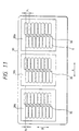
- Fig. 11 shows an embodiment in terms of the relative positions between the nozzles 3 and the pressure producing chambers 5, the embodiment being characterized as forming dots by causing the actuator units 30a, 30b, 30c to correspond to the colors, cyan, magenta, and yellow.
- This recording head has the nozzles of different colors arranged at the same positions in the auxiliary scanning direction B so that the nozzles of the respective colors can produce an ink image at the same positions.
- two arrays of pressure producing chambers, which are pitched at an interval of P1 confront each other, with one array being staggered with respect to the other by an interval of P2, which is a half of the interval P1, in the auxiliary scanning direction.
- the nozzle density in the auxiliary scanning direction is substantially set to P2.
- the ink jet recording head of the invention is characterized as producing the best image only by adjusting both the shape of each nozzle 3 of the flow path unit 60 and the shape of each of the ink supply inlets 4a, 4b, 4c optimally per ink even if all the actuator units are of the same design. As a result, it is actuator units of the same design that are required to be fabricated, which in turn contributes to a cost reduction brought about by mass production.
- an ink jet recording head capable of jetting ink droplets in differing amounts from the respective nozzle groups 3a, 3b, 3c can be formed only by changing the shape of each nozzle 3 or the shape of each ink supply inlet 4 of the flow path unit 60, the ink jet recording head characterized as smoothly changing the density can be provided even if the actuator units of the same design are used.
- Fig. 12 shows an embodiment in which an ink jet recording head having a high dot density is formed by using a plurality of actuator units 30a, 30b, 30c.
- nozzles are pitched at an interval of 6p in each of two arrays that belong to each of the actuator units 30a, 30b, 30c, and these nozzles in each array are staggered by p in the auxiliary scanning direction B. Since the pressure producing chambers in the two corresponding arrays are staggered by 3p in the auxiliary scanning direction B, each nozzle is arranged toward one side with respect to the central axis of the corresponding pressure producing chamber.
- the nozzles are pitched at an interval of p when viewed in the main scanning direction A. That is, using the pressure producing chambers 5 pitched at an interval of 6p, dots are formed at a density six times the interval.
- the embodiment which is characterized as mounting a plurality of actuator units on the single common flow path unit 60, can provide a recording head accommodating diverse uses only by changing the positions at which the actuator units of the same design are fixed to the single flow path unit.
- the actuator units are mounted on the single flow path unit 60 so as to be scattered around, not only heat produced by the piezoelectric vibration elements can be quickly radiated, but also the positioning and dimensional accuracy of each nozzle can be regulated by the flow path unit made of metal or the like that can form through holes with relatively high accuracy.
- the actuator units that become hard to sinter as the size thereof is increased can be downsized.
- the embodiment is characterized as fixing a flow path unit to a plurality of actuator units so as to correspond to groups of nozzles; i.e., the flow path unit is formed by laminating a nozzle plate, a reservoir chamber forming board, and a seal board, the nozzle plate having nozzles divided into a plurality of groups, the reservoir chamber forming board having a plurality of reservoir chambers belonging to the respective groups of nozzles and having communicating holes respectively communicating with the nozzles, and the ink supply inlet forming board being fixed to a surface of the reservoir chamber forming board and having communicating holes for communicating with pressure producing chambers and nozzles; and each actuator unit including a pressure producing chamber forming board, a vibration plate, and piezoelectric vibration elements, the pressure producing chamber forming board having a plurality of pressure producing chambers defined by side walls, the vibration plate being fixed to a surface of the pressure producing chamber forming board, and the piezoelectric vibration elements being formed on a surface of the vibration plate so as
- the flow path unit serving also as the actuator unit fixing board can be made of metal that is comparatively easy to ensure proper accuracy by pressure working or the like, which not only allows nozzles with high positioning accuracy to be formed, but also contributes to downsizing the actuator unit made of ceramic that can be fixed by sintering and therefore improving yield of fabrication.
- a recording head adapted for various uses only by changing the structure of a flow path unit whose design can be modified relatively easily can be provided.
Landscapes
- Engineering & Computer Science (AREA)
- Manufacturing & Machinery (AREA)
- Physics & Mathematics (AREA)
- Optics & Photonics (AREA)
- Particle Formation And Scattering Control In Inkjet Printers (AREA)
Abstract
Description
- The invention relates to a laminated ink jet recording head.
- On-demand ink jet recording heads that are designed to output characters and graphics by jetting ink droplets from a plurality of nozzles in accordance with input information are rapidly gaining in popularity because of their high print quality and low noise compared with wire-dot type recording heads and because of their low running cost compared with page printers.
- Among these ink jet recording heads, a so-called face-ejected ink jet head, which is designed to jet ink droplets in a direction perpendicular to the surface of a plate by arranging a plurality of nozzles on the plate, has features that a high degree of freedom is given to nozzle arrangement and that the head can be manufactured relatively simply because of a laminated structure.
- Fig. 13 shows an exemplary ink jet recording head having the aforementioned laminated structure. A
channel plate 94 defining slenderpressure producing chambers 96 on a flat surface has one surface thereof sealed by avibration plate 95 havingpiezoelectric vibration elements 97 formed so as to correspond topressure producing chambers 96, and the other surface thereof sealed by a regulatingplate 93 having regulatingorifices 98. - A
manifold plate 92 laminated on the surface of the regulatingplate 93 has through holes that definereservoir chambers 99 for supplying ink to the respectivepressure producing chambers 96 via theregulating orifices 98.Flow paths vibration plate 95, thechannel plate 94, and theregulating plate 93 are formed for thereservoir chambers 99. - Further,
nozzles 90 are formed in anozzle plate 103 that is fixed to a side opposite to thevibration plate 95. Communicatingholes nozzles 90 to the respective pressure producing chambers are formed so as to extend through theregulating plate 93 and themanifold plate 92. - This laminated ink jet recording head is characterized in that the respective pressure producing chambers are typically arranged in two arrays so as to confront each other at an interval of from 1.01 to 1.53 mm (0.04 to 0.06 inches) within an array and are alternately connected to the nozzles pitched at an interval of from 0.50 to 0.77 mm (0.02 to 0.03 inches) within the single array.
- By the way, to improve the recording quality of such ink jet recording head, it is necessary to increase the density of pixels to be recorded by downsizing an ink droplet to be jetted. Further, to ensure proper recording speed with the pixel density satisfied, it is necessary to increase the number of nozzles that jet ink droplets. Color printing, in particular, that forms a single pixel by three to four colors necessarily requires a great number of nozzles as well as a complicated flow path structure that can introduce the ink to such a great number of nozzles.
- Particularly, to improve recording quality by increasing the density of pixels to be recorded, it is necessary to increase the nozzle arrangement density, which complicates the flow path structure between an ink containing section and the individual nozzles. This holds true not only for the plane dimensions and arrangement but for the thickness as well. To machine a smaller through hole in a plate in terms of the plane dimensions, it is necessary to reduce the thickness to a degree equal to the diameter of the hole.
- Another aspect of the invention is to provide a novel laminated ink jet recording head that can be prepared inexpensively by utilizing the properties of two units, one being made of a metal material and the other being made of a ceramic material.
- Another object of the invention is to avoid damage to the recording head when the recording head is placed in a low temperature environment.
- This object is solved by the laminated ink jet recording head of independent claim 1. Further advantageous features, aspects and details of the invention are evident from the dependent claims, the description and the drawings. The claims are intended to be understood as a first non-limiting approach of defining the invention in general terms.
- The invention provides an ink jet recording head which is formed by laminating plate members and which is designed to form a dot on a recording sheet by splashing an ink droplet upon reception of an input of print data.
- To achieve the above aspects, the invention according to a specific aspect preferably provides a laminated ink jet recording head that has a flow path unit being formed by laminating a nozzle plate, a reservoir chamber forming board, and an ink supply inlet forming board, the reservoir chamber forming board having a plurality of reservoir chambers having communicating holes respectively communicating with the nozzles, and the ink supply inlet forming board being fixed to a surface of the reservoir chamber forming board and having communicating holes for communicating with pressure producing chambers and nozzles. In such laminated ink jet recording head, preferably a plurality of actuator units are fixed to the flow path unit so as to correspond to the groups of nozzles, each actuator unit advantageously including a pressure producing chamber forming board, a vibration plate, and piezoelectric vibration elements. The pressure producing chamber forming board preferably has a plurality of pressure producing chambers defined by side walls, the vibration plate being fixed advantageously to a surface of the pressure producing chamber forming board, and/or the piezoelectric vibration elements being formed on a surface of the vibration plate so as to correspond to the pressure producing chambers.
- The flow path unit serving also as the actuator fixing board is preferably made of metal that is relatively easy to ensure accuracy by press working or the like, and the actuator unit is advantageously made of ceramic that can be secured by sintering, so that accuracy in forming the nozzles of the flow path unit can be fully utilized.
- Fig. 1 is an exemplary recording apparatus to which an ink jet recording head of the invention is applied;
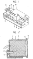
- Fig. 2 is an exemplary ink jet recording head of the inventions;
- Fig. 3 is a diagram showing an ink jet recording head formed by fixing a single actuator unit to a flow path unit;
- Fig. 4 is a diagram showing a structure of the recording head of Fig. 3 on the actuator unit side;
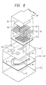
- Fig. 5 is an exploded perspective view showing an internal structure of the recording head of Fig. 3;
- Fig. 6 is a diagram showing a structure in section of the recording head of Fig. 3;
- Figs. 7 (A) to (C) are diagrams showing a method of preparing an actuator unit used in the recording head of the invention;
- Fig. 8 is a diagram showing another embodiment of the recording head of Fig. 3;
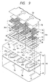
- Fig. 9 is an exploded perspective view showing an ink jet recording head, which is an embodiment of the invention;
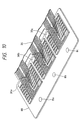
- Fig. 10 is a diagram showing the ink jet recording head of the invention in the form of a structure of a side on which actuator units are mounted;
- Fig. 11 is a diagram showing an ink jet recording head, which is another embodiment of the invention, in the form of an arrangement of pressure producing chambers and nozzles;
- Fig. 12 is a diagram showing an ink jet recording head, which is another embodiment of the invention, in the form of an arrangement of pressure producing chambers and nozzles; and
- Fig. 13 is a diagram showing an exemplary conventional laminated ink jet recording head.
-
- Details of the invention will now be described with reference to embodiments shown in the drawings.
- Fig. 1 is an exemplary recording apparatus to which a laminated ink jet recording head of the invention is applied.
- In Fig. 1,
reference numeral 2 denotes a print mechanism section. Acarriage 80 is moved in main scanning directions (in the directions indicated by arrows A in Fig. 1) by acarriage motor 81. Arecording medium 82 is moved in auxiliary scanning directions (in the directions indicated by arrows B in Fig. 1) by a sheetforward motor 84 while positioned by aplaten 83. - As shown in Fig. 2, the
print mechanism section 2 consists of an inkjet recording head 10 described later, anink containing section 70 and ahead fixing member 20 for fixing the inkjet recording head 10 and theink containing section 70. - The
ink containing section 70 contains anink containing member 74 in the container which is secured by alid 77 having anatmosphere communicating hole 76. Moreover, a flow path is defined by anink supply tube 72 in such a manner that one end there of is connected to the inkjet recording head 70 and the other end thereof extends to theink containing section 70 so as to supply the ink to theink recording head 10. Areference numeral 71 denotes an O-ring for sealing, and areference numeral 75 denotes filter provided with theink supply tube 72. - As a result of this construction, the
recording head 10 forms an image on a two-dimensional plane by jetting an ink droplet while moving in the main scanning directions in accordance with a print signal and having a recording medium moved in the auxiliary scanning direction every time a single line of characters or the like has been printed with ink supplied from theink containing section 70. - In addition, when no printing is done for more than a predetermined time, the
recording head 10 is evacuated to a stand-byposition 86 where anink sucking means 85 is provided. The ink sucking means 85 has acap 87 and a not shown cap moving mechanism, and waits in a stand-by position with thecap 87 abutted against the nozzle surface of therecording head 10. - While the ink containing section is carried on the
carriage 80 in the aforementioned embodiment, the ink may be supplied to therecording head 10 through a tube by arranging an ink tank on a case or the like. - Figs. 3 and 4 show an embodiment of the aforementioned ink
jet recording head 10. Therecording head 10 is formed by fixing a plate-like actuator unit 30 on a surface of a similar plate-likeflow path unit 40 whose area is large enough to mount theactuator unit 30 thereon. An end of aflexible cable 26 is connected to one surface of theactuator unit 30, the flexible cable serving to apply a drive signal to a piezoelectric vibration element, which will be described later. - Fig. 5 shows an embodiment of the actuator unit. The
actuator unit 30 is formed by sequentially laminating aseal board 31, a pressure producingchamber forming board 32, and avibration plate 33.Lower electrodes 35 are formed on thevibration plate 33 while separated from one another so as to correspond to respectivepressure producing chambers 5.Piezoelectric vibration elements 34, each being made of an electrostrictive material, are formed so as to correspond to the surfaces of thelower electrodes 35 in the form of a layer. Anupper electrode 36 is formed on the surfaces of thepiezoelectric vibration elements 34 so that thepiezoelectric vibration elements 34 are interposed between thelower electrodes 35 and theupper electrode 36 with theupper electrode 36 stretching over a plurality ofpiezoelectric vibration elements 34. - That is, a drive signal is applied individually to a
lower electrode 35 so that apiezoelectric vibration element 34 is selectively driven. Theupper electrode 36 serving as a common electrode and thelower electrodes 35 serving as individual electrodes are connected to an external drive circuit through aconnection terminal 37 formed on thevibration plate 33 and a flexible printed board (FP). The respectivepressure producing chambers 5 for producing pressure necessary for jetting ink droplets have arrangement thereof on a plane regulated by slender through holes formed in the pressure producingchamber forming board 32, The peripheral wall of each through hole serves as a side wall to define and separate pressure producing chambers from one another. - Further, the
seal board 31 is not only bonded to the side walls so as to be airtight in order to seal thepressure producing chambers 5 and provides the bottom wall for thepressure producing chamber 5, but also has first communicatingholes 38 and second communicatingholes 39 formed so that bothholes pressure producing chamber 5 in the vicinity of both ends of thepressure producing chamber 5. Each first communicatinghole 38 serves to supply the ink with the corresponding pressure producing chamber from outside the actuator unit, and eachsecond communicating hole 39 serves to connect to acorresponding nozzle 3 that jets an ink droplet. - The
flow path unit 40 is formed by sequentially laminating anozzle plate 41, a reservoirchamber forming board 42, and an ink supplyinlet forming board 43. The reservoirchamber forming board 42 has a through hole for defining areservoir chamber 6 formed. Thereservoir camber 6 is formed by having one end of the surface thereof sealed by thenozzle plate 41 and the other end of the surface thereof sealed by the ink supplyinlet forming board 43. Thereservoir chamber 6 functions as a manifold for branching the ink from theink containing section 74 into the respectivepressure producing chambers 5, and extends from a portion overlapping the respectivepressure producing chambers 5 in terms of a plane to a portion not overlapping theactuator unit 30 in terms of a plane as viewed from the board surface. - In the
reservoir chamber 6,ink supply inlets 4 for supplying the ink to the individualpressure producing chambers 5 from thereservoir chamber 6 are formed in a portion of the reservoirchamber forming board 42 overlapping the respectivepressure producing chambers 5 in terms of a plane, whereas areservoir inlet 8 for introducing the ink from theink containing section 74 to thereservoir chamber 6 is formed in a region not overlapping theactuator unit 30 in terms of a plane. In addition, thenozzle plate 41 hasnozzles 3 for jetting ink droplets formed so as to correspond to thepressure producing chambers 5. To connect thenozzles 3 to the correspondingpressure producing chambers 5, nozzle communication holes 44, 45 are arranged in the ink supplyinlet forming board 43 and the reservoirchamber forming board 42 so as to correspond to thenozzles 3, respectively. - The
ink supply inlets 4 and the nozzle communication holes 44, which are opened onto one of the surfaces of theflow path unit 40 are formed at positions overlapping the first communicatingholes 38 and the second communicatingholes 39 of theactuator unit 30 to which theink supply inlets 4 and the nozzle communication holes 44 correspond on a one-by-one basis. The flow paths between the respective units are connected to one another by bonding theactuator unit 30 to theflow path unit 40 with the corresponding openings thereof overlapping upon one another. - Flow of the ink within the
head unit 10 formed of theflow path unit 40 and theactuator unit 30 will be described with reference to Fig. 6, which shows a structure in section taken along a slender pressure producing chamber. - Fig. 6 shows the
reservoir inlet 8 arranged in the same section as thepressure producing chamber 5 for simplification of the description. The ink introduced from the ink containing section is supplied to thepressure producing chamber 5 via thereservoir inlet 8, thereservoir chamber 6, theink supply inlet 4, and the communicatinghole 38. The ink supply inlet is designed so that when the ink is initially charged into the flow path, or when bubbles are produced within the flow path, or when the viscosity of the ink is increased, the ink or bubbles are forcibly sucked from thenozzle 3 and discharged using theink sucking means 85. - Further, at the time of printing, a capillary force derived from a meniscus formed in the
nozzle 3 causes the ink to flow into thepressure producing chamber 5 from the ink containing section. Thepiezoelectric vibration element 34 constitutes an unimorph vibration element together with thevibration plate 33. Thepiezoelectric vibration element 34 is contracted toward the surface by the application of a voltage thereto. Thevibration plate 33 flexes in such a direction as to contract thepressure producing chamber 5, thus producing pressure in thepressure producing chamber 5. From this pressure is an ink stream produced, the ink stream extending from thepressure producing chamber 5 to thenozzle 3 via the second communicatingholes 39 and the nozzle communication holes 44, 45, and this ink stream is jetted from thenozzle 3 in the form of an ink droplet. - By the way, the
nozzle plate 41 has a two-layered structure with athin wall portion 41a and athick wall portion 41b. Thethin wall portion 41a exists only in the vicinity of the communicatinghole 45 that is connected to thenozzle 3. - This
nozzle plate 41 is formed by forming thenozzle 3 by press-working a metal plate that is resiliently deformable by the ink pressure from thepressure producing chamber 5, and thereafter plating a region excluding the vicinity of thenozzle 3 by chromium or the like to such a thickness as to ensure proper strength to thereby form thethick wall portion 41b. - Because the
nozzle plate 41 has thethin wall portion 41a only in the vicinity of thenozzle 3 and thethick wall portion 41b in the other region, thethin wall portion 41a in the vicinity of the communicatinghole 45 is resiliently deformed in response to the pressure derived from thepressure producing chamber 5. This not only ensures compliance necessary for jetting an ink droplet, but also contributes to increasing rigidity of a recording head to thereby minimize flexion thereof in the case where the recording head has a plurality of actuator units fixed thereto, which recording head will be described later. Since thenozzle 3 is positioned one stage below, contact of thethin wall portion 41a with a recording sheet or the like can also be prevented. - This embodiment is characterized as having two arrays of
pressure producing chambers 5 formed so as to confront asingle actuator unit 30. Thepressure producing chambers 5 in one array are staggered with respect to those in the other array along the length of each array by a distance half the distance between the adjacentpressure producing chambers 5 in a single array. Further, the correspondingnozzles 3 are similarly arranged in two arrays so that thenozzles 3 in one array are staggered with respect to those in the other array by a distance half the distance between theadjacent nozzles 3 in a single array. Therefore, the distance between theadjacent nozzles 3 as viewed in the main scanning directions A is equal to a distance half the distance between the adjacent pressure producing chambers, thereby making thenozzle 3 arrangement density substantially twice. - Although only one or three or more arrays of pressure producing chambers may be arranged in a
single actuator unit 30, the two-array design allows feeder lines to be arranged in spaces on both sides of theactuator unit 30, which in turn contributes to simplifying the wiring structure. - Further, while the ink is supplied to the two arrays of pressure producing chambers through the V-shaped or U-shaped
common reservoir chamber 6 in the aforementioned embodiment, reservoir chambers dedicated to the respective arrays of pressure producing chambers may be arranged to allow ink droplets of different colors to be jetted from the respective nozzle arrays. - Specific embodiments of the aforementioned
flow path unit 40 will be described next. -
Nozzles 3, each being a tapered hole whose opening diameter ranges from 30 to 50 µm, are arranged in two arrays at an inter-array interval of 564 µm on thenozzle plate 41 made of a stainless steel plate whose thickness ranges from 50 to 150 µm. The reservoirchamber forming board 42 has a through hole for defining thereservoir chamber 6 and the nozzle communication holes 45 formed by press working a 150 µm-thick stainless steel plate. - The diameter of the
nozzle communication hole 45 is preferably set to 150 µm similarly to the thickness of the plate. The ink supplyinlet forming board 43 has both theink supply inlets 4 and the nozzle communication holes 44 formed by press working a stainless steel plate whose thickness ranges from 50 to 150 µm. The fluid impedance of theink supply hole 4 is preferably set to a value equal to or greater than the fluid impedance of the nozzle so that an ink stream produced by the pressure of thepressure producing chamber 5 is directed toward thenozzle 3 by checking the ink stream from going toward thereservoir chamber 6. - In this embodiment, the
ink supply inlet 4 is set to the same dimensions as thenozzle 3, and the section thereof is tapered toward the first communicatinghole 38. Because of the taper, the diameter of the narrowest portion of theink supply inlet 4 can be made smaller than the thickness of the plate, and in addition theink supply inlet 4 can be formed accurately. The diameter of thenozzle communication hole 44 is larger than that of thenozzle communication hole 45 of the reservoirchamber forming board 43 and smaller than the width of thepressure producing chamber 5, ranging from 200 to 300 µm. As a result of this design, the flow path from thepressure producing chamber 5 to thenozzle 3 can be gradually narrowed, thereby preventing bubbles from stagnating along the flow path. - The three plates constituting the flow path unit are laminated so that the through holes related to one another can communicate with one another. These plates may be brazed, subjected to diffused junction, or bonded with an adhesive or a blanked adhesive sheet, or the like. In this embodiment, these plates are bonded with an adhesive made from an epoxy resin that is not corroded by ink.
- While each plate is made of a stainless steel plate in this embodiment, a material of which each plate is made may be appropriately selected and combined in accordance with the function of the plate from inorganic materials such as ceramic, silicon and glass, metals such as nickel, or plastic materials such as polyimide, polycarbonate, and polysulfone as long as such materials are not corroded by ink.
- The plastic plates may be subjected to excimer laser machining, or electroplating using nickel because the
nozzle plate 41 and the ink supplyinlet forming board 43 are comparatively thin, have holes whose diameters are small, and require high accuracy. - In this invention, the
flow path unit 40, serving also as theactuator unit 30 fixing board, requires high rigidity. Therefore, a metal having both toughness and rigidity is preferred to make theflow path unit 40. Since the reservoirchamber forming board 42, in particular, has the through hole whose size is larger than those formed in the other plates, the use of a plate thicker than the other plates is preferred to provide a structure that can ensure proper rigidity. - A specific embodiment of the
actuator unit 3 will be described next. The pressure producingchamber forming board 32 is a 150 µm-thick sintered body of zirconia, and has a plurality ofpressure producing chambers 5 arranged in two arrays at an inter-array interval of 564 µm similarly to thenozzles 3. The width of eachpressure producing chamber 5 ranges from 350 to 450 µm, and the length thereof ranges from 1 to 3 mm. These dimensions are set to optimal values in function of the magnitude of an ink droplet required for forming a dot, the nozzle arrangement density, and the like. - The
seal board 31 is a 150 µm-thick sintered body of zirconia, and is bonded to one surface of the pressure producingchamber forming board 32 so as to seal one surface of eachpressure producing chamber 5. The diameter of each of a pair of communicatingholes vibration plate 33 is a sintered body of zirconia whose thickness ranges from 10 to 20 µm, and is bonded so as to seal the other surface of eachpressure producing chamber 5. Thelower electrodes 35 are formed on thevibration plate 33 so as to correspond to thepressure producing chambers 5, and on the surfaces of thelower electrodes 35 are thepiezoelectric vibration elements 34. Eachpiezoelectric vibration element 34 is formed by laminating a piezoelectric ceramic material such as lead titanate zirconate on the correspondinglower electrode 35. The width of thepiezoelectric vibration element 34 is set to values ranging from 80 to 90% of the width of thepressure producing chamber 5, and the thickness thereof ranges from 20 to 40 µm. It should be noted that other ceramic materials such as alumina, aluminum nitride, lead titanate zirconate may replace zirconia. - A method of preparing the aforementioned actuator unit will be described next.
- As shown in Fig. 7 (A), the
vibration plate 33, the pressure producingchamber forming board 32 having the through holes for defining thepressure producing chambers 5 already punched out, and theseal board 31 having the communicating holes already punched out are bonded to one another by pressure in the form of a green sheet, i.e., in clay-like form, and the thus bonded boards are thereafter integrally sintered at temperatures ranging from 800 to 1000°C. As a result of this method, the respective boards are bonded together without an adhesive. - Then, as shown in Fig. 7 (B), an electrode pattern is prepared by printing a material so that portions corresponding to the
pressure producing chambers 5 will become thelower electrodes 35, the material having as a main component thereof at least one kind of alloys composed of platinum, palladium, silver-palladium, silver-platinum, and platinum-palladium. - Thereafter, as shown in Fig. 7 (C), the
piezoelectric members 34 are laminated on the lower electrodes similarly by printing and sintered to complete the actuator unit. Finally, a common electrode made of chromium, gold, nickel, or the like is formed by sputtering so as to stretch over a plurality of piezoelectric vibration elements. - The integrally sintered
actuator unit 30 has the extremely minutely structured pressure producingchamber forming board 32 and thethin vibration plate 33 bonded together rigidly thereto. Therefore, excellent airtightness and corrosion resistance against ink are exhibited. In addition, the method of preparing theactuator unit 30, involving such simple steps of laminating the clay boards, applying the paste-like electrode and piezoelectric vibration element materials by printing, and sintering all these members, allows theactuator unit 30 to be manufactured extremely easily as well as accurately. - Although the aforementioned method of forming the
actuator unit 30 characterized as integrally sintering the materials is quite excellent, the actuator unit may be formed by combining such conventional methods as a method of bonding boards made of metal or resin by adhesion, deposition, or fusion, a method of etching glass or silicon boards, a plastic molding method, and a method of mounting piezoelectric vibration element chips on the vibration plate. - While the ink stream from the
pressure producing chamber 5 to thereservoir chamber 6 is regulated by theink supply inlet 4 arranged in theflow path unit 40 in the aforementioned embodiment, the first communicatinghole 38 formed in theactuator unit 30 may be constricted to such a size as to regulate return of the ink. - Further, the ink
jet recording head 10 of the invention is characterized not only as setting the heat capacity of the actuator unit 30 (determined by the product of the material density, the specific heat, and the volume) to a value smaller than the heat capacity of theflow path unit 40, but also as fixing the inkjet recording head 10 to thehead fixing member 20 so that theactuator unit 30 can communicate with the atmosphere. - As a result of this construction, problems such as expansion of the
pressure producing chamber 5 due to freezing of the ink from thenozzle plate 41 side of theflow path unit 40 caused when the recording head is placed in a low temperature environment, and breakage of thevibration plate 33 due to such freezing can be overcome, which allows the ink to start freezing on the actuator unit side, and hence allows pressure produced within the flow path due to freezing to be released to the flow path unit side (to the atmosphere through the nozzles). - Fig. 8 shows another embodiment of the
actuator unit 30, which is characterized as having the openings of thepressure producing chambers 5 onto one surface of theactuator unit 30 without arranging theaforementioned seal board 31 and sealing the openings instead by the ink supplyinlet forming board 43 of theflow path unit 40. This embodiment is advantageous in curtailing the number of parts involved, which in turn contributes to reducing the cost of manufacture. - Techniques for constructing various recording heads using a plurality of the
aforementioned actuator units 30 will be described next with reference to Figs. 9 and 10. - In Figs. 9, 10,
reference numeral 60 denotes a flow path unit, which is formed by laminating anozzle plate 61, a reservoirchamber forming board 62, and an ink supplyinlet forming board 63. These plate andboards nozzle groups actuator units - The
nozzle plate 61 has not only thenozzle groups group having nozzles 3, but also athin wall portion 41a in the vicinity of eachnozzle 3 as shown in Fig. 6 in order to ensure compliance. - The reservoir
chamber forming board 62 has through holes definingreservoir chambers reservoir chambers nozzle plate 61 and the other surface thereof by the ink supplyinlet forming board 63. The reservoirchamber forming board 62 functions as a manifold for branching ink from theink containing section 74 to respectivepressure producing chambers -
Ink supply inlets 4a, 4b, 4c for supplying the ink to thepressure producing chambers respective actuator units reservoir chambers path forming board 63 overlapping thepressure producing chambers Reservoir inlets ink containing section 74 are formed at regions of the ink flowpath forming board 63 not overlapping theactuator units -
Ink supply inlets 4a, 4b, 4c and nozzle communication holes 64a, 64b, 64c opening onto one surface of theflow path unit 60 are formed at positions overlapping the first communicatingholes 38 and the second communicatingholes 39 of theactuator units actuator units flow path unit 60 so that the corresponding openings can be aligned with one another, the flow paths of the threeactuator units flow path unit 60. - As described above, the
flow path unit 60 has thereservoir chambers reservoir inlets respective reservoir chambers respective nozzle groups - Further, the
flow path unit 60 is advantageous in that theflow path unit 60 can not only form nozzle openings at high accuracy by press working, which is a simple working method, but also use metal whose rigidity is comparatively high as a main material. On the other hand, theactuator units - As a result, a downsized recording head having nozzles arranged at high density with high accuracy can be fabricated at high yield by not only downsizing the
actuator units flow path unit 60 having the nozzles formed with high positioning accuracy. - In addition, since the
piezoelectric vibration element 34 to which a drive signal is applied can be formed on thevibration plate 33 made of ceramic that is basically electrically insulating, no special insulating process for the formation of electrodes is necessary any longer. - Fig. 11 shows an embodiment in terms of the relative positions between the
nozzles 3 and thepressure producing chambers 5, the embodiment being characterized as forming dots by causing theactuator units - This recording head has the nozzles of different colors arranged at the same positions in the auxiliary scanning direction B so that the nozzles of the respective colors can produce an ink image at the same positions. Taking a look at a single color, two arrays of pressure producing chambers, which are pitched at an interval of P1 confront each other, with one array being staggered with respect to the other by an interval of P2, which is a half of the interval P1, in the auxiliary scanning direction. As a result of this arrangement, the nozzle density in the auxiliary scanning direction is substantially set to P2.
- Since the property of an ink is generally differant from that of another, it is difficult to produce the best image by giving the same design to the flow paths for the respective inks. However, the ink jet recording head of the invention is characterized as producing the best image only by adjusting both the shape of each
nozzle 3 of theflow path unit 60 and the shape of each of theink supply inlets 4a, 4b, 4c optimally per ink even if all the actuator units are of the same design. As a result, it is actuator units of the same design that are required to be fabricated, which in turn contributes to a cost reduction brought about by mass production. - Further, since an ink jet recording head capable of jetting ink droplets in differing amounts from the
respective nozzle groups nozzle 3 or the shape of eachink supply inlet 4 of theflow path unit 60, the ink jet recording head characterized as smoothly changing the density can be provided even if the actuator units of the same design are used. - Fig. 12 shows an embodiment in which an ink jet recording head having a high dot density is formed by using a plurality of
actuator units actuator units - Since the three
actuator units pressure producing chambers 5 pitched at an interval of 6p, dots are formed at a density six times the interval. - As described above, the embodiment, which is characterized as mounting a plurality of actuator units on the single common
flow path unit 60, can provide a recording head accommodating diverse uses only by changing the positions at which the actuator units of the same design are fixed to the single flow path unit. - Further, since the actuator units are mounted on the single
flow path unit 60 so as to be scattered around, not only heat produced by the piezoelectric vibration elements can be quickly radiated, but also the positioning and dimensional accuracy of each nozzle can be regulated by the flow path unit made of metal or the like that can form through holes with relatively high accuracy. In addition, the actuator units that become hard to sinter as the size thereof is increased can be downsized. - As described in the foregoing, the embodiment, is characterized as fixing a flow path unit to a plurality of actuator units so as to correspond to groups of nozzles; i.e., the flow path unit is formed by laminating a nozzle plate, a reservoir chamber forming board, and a seal board, the nozzle plate having nozzles divided into a plurality of groups, the reservoir chamber forming board having a plurality of reservoir chambers belonging to the respective groups of nozzles and having communicating holes respectively communicating with the nozzles, and the ink supply inlet forming board being fixed to a surface of the reservoir chamber forming board and having communicating holes for communicating with pressure producing chambers and nozzles; and each actuator unit including a pressure producing chamber forming board, a vibration plate, and piezoelectric vibration elements, the pressure producing chamber forming board having a plurality of pressure producing chambers defined by side walls, the vibration plate being fixed to a surface of the pressure producing chamber forming board, and the piezoelectric vibration elements being formed on a surface of the vibration plate so as to correspond to the pressure producing chambers. Therefore, the flow path unit serving also as the actuator unit fixing board can be made of metal that is comparatively easy to ensure proper accuracy by pressure working or the like, which not only allows nozzles with high positioning accuracy to be formed, but also contributes to downsizing the actuator unit made of ceramic that can be fixed by sintering and therefore improving yield of fabrication. In addition, even if a plurality of actuator units of the same design are used, a recording head adapted for various uses only by changing the structure of a flow path unit whose design can be modified relatively easily can be provided.
Claims (10)
- An ink jet recording head comprising:a laminated ink jet recording unit (10) having:(a) a flow path unit (40;60) including:wherein the nozzle plate (41;61), the reservoir chamber forming board (62) and the ink supply inlet forming board (63) are laminated to form the flow path unit (40;60); anda nozzle plate (41;61) having a plurality of nozzles (3;3a,3b,...);a reservoir chamber forming board (42;62) having a plurality of reservoir chambers (6;6a,6b,...) and having communicating holes (45;65a,65b,...) respectively communicating with the nozzles (3;3a,3b,...);an ink supply inlet forming board (43;63) fixed to a surface of the reservoir chamber forming board (42;62) and having communicating holes (44;64) for communicating with pressure producing chambers (5;5a,5b,...) and nozzles (3;3a,3b,...);(b) an actuator unit (30;30a,30b,...) including:wherein the flow path unit (40;60) is connected to the actuator unit (30;30a,30b,...) in such a manner that the communicating holes (4,44;4a,4b,...,64a,64b,...) of the ink supply inlet forming board (63) of the flow path unit communicate with the corresponding pressure producing chambers (5;5a,5b,...) to form the laminated ink jet recording unit (10);a pressure producing chamber forming board (32) having a plurality of the pressure producing chambers (5;5a,5b,...) defined by side walls;a vibration plate (33) fixed to a surface of the pressure producing chamber forming board (32); andpiezoelectric vibration elements (34) being formed on a surface of the vibration plate (33) so as to correspond to the pressure producing chambers (5;5a,5b,...);the ink jet recording head further comprising:(c) a head fixing member (20) on which the laminated ink jet recording unit (10) is fixed such that the actuator unit (30;30a,30b,...) communicates with the atmosphere.
- The ink jet recording head according to claim 1, wherein a heat capacity of the actuator unit (30;30a,30b,...) is set to be smaller than a heat capacity of the flow path unit (40;60).
- The ink jet recording head according to claim 1 or 2, wherein the actuator unit (30;30a,30b,...) and the flow path unit (40;60) are adapted such that, when the ink jet recording head is placed in a low temperature environment, ink contained in the actuator unit (30;30a,30b,...) and the flow path unit (40;60) communicating with the actuator unit (30;30a,30b,...) starts freezing on the actuator unit side.
- The ink jet recording head according to one of claims 1 to 3, wherein the flow path unit (40;60) comprises a metal plate and is fixed with an adhesive.
- The ink jet recording head according to one of claims 1 to 4, wherein said actuator unit (30;30a,30b,...) is made of ceramic and fixed by sintering.
- The ink jet recording head according to one of claims 1 to 5, wherein the ink supply inlet forming board (43;63) has communicating holes (8;8a,...) for supplying ink to the respective reservoir chambers (6;6a,...) from outside.
- The ink jet recording head according to one of claims 1 to 6, wherein the nozzles (3;3a,3b,...) are arranged in groups wherein the nozzles (3;3a,3b,...) are staggered by a predetermined interval for each group.
- The ink jet recording head according to one of claims 1 to 7, wherein the nozzles (3;3a,3b,...) are divided into three groups (30;30a,30b,...) and inks of different colour are supplied to the reservoir chambers belonging to the respective groups.
- The ink jet recording head according to one of claims 1 to 8, wherein a flexible cable (26) is connected to the actuator unit (30).
- The ink jet recording head according to one of claims 1 to 9, wherein said nozzle plate has a thin wall portion (41a) in the vicinity of each nozzle (3).
Applications Claiming Priority (7)
| Application Number | Priority Date | Filing Date | Title |
|---|---|---|---|
| JP32858393 | 1993-12-24 | ||
| JP32858393 | 1993-12-24 | ||
| JP15374594 | 1994-07-05 | ||
| JP15374594A JP3384418B2 (en) | 1994-07-05 | 1994-07-05 | Inkjet recording head |
| JP33587494 | 1994-12-22 | ||
| JP33587494A JP3610987B2 (en) | 1993-12-24 | 1994-12-22 | Multilayer ink jet recording head |
| EP94120573A EP0659562B1 (en) | 1993-12-24 | 1994-12-23 | Laminated ink jet recording head |
Related Parent Applications (2)
| Application Number | Title | Priority Date | Filing Date |
|---|---|---|---|
| EP94120573.4 Division | 1994-12-23 | ||
| EP94120573A Division EP0659562B1 (en) | 1993-12-24 | 1994-12-23 | Laminated ink jet recording head |
Publications (3)
| Publication Number | Publication Date |
|---|---|
| EP1170127A2 true EP1170127A2 (en) | 2002-01-09 |
| EP1170127A3 EP1170127A3 (en) | 2002-05-08 |
| EP1170127B1 EP1170127B1 (en) | 2005-10-19 |
Family
ID=27320527
Family Applications (2)
| Application Number | Title | Priority Date | Filing Date |
|---|---|---|---|
| EP01125003A Expired - Lifetime EP1170127B1 (en) | 1993-12-24 | 1994-12-23 | Ink jet recording head |
| EP94120573A Expired - Lifetime EP0659562B1 (en) | 1993-12-24 | 1994-12-23 | Laminated ink jet recording head |
Family Applications After (1)
| Application Number | Title | Priority Date | Filing Date |
|---|---|---|---|
| EP94120573A Expired - Lifetime EP0659562B1 (en) | 1993-12-24 | 1994-12-23 | Laminated ink jet recording head |
Country Status (4)
| Country | Link |
|---|---|
| US (3) | US6502929B1 (en) |
| EP (2) | EP1170127B1 (en) |
| DE (2) | DE69431036T2 (en) |
| SG (1) | SG54175A1 (en) |
Families Citing this family (24)
| Publication number | Priority date | Publication date | Assignee | Title |
|---|---|---|---|---|
| JP3570447B2 (en) | 1994-12-21 | 2004-09-29 | セイコーエプソン株式会社 | Laminated inkjet recording head, method of manufacturing the same, and recording apparatus |
| US5907340A (en) * | 1995-07-24 | 1999-05-25 | Seiko Epson Corporation | Laminated ink jet recording head with plural actuator units connected at outermost ends |
| EP0985536B1 (en) * | 1995-11-10 | 2002-09-25 | Seiko Epson Corporation | Ink jet type recording head |
| US6190006B1 (en) | 1997-11-06 | 2001-02-20 | Seiko Epson Corporation | Ink-jet recording head |
| US7216956B2 (en) * | 1998-10-16 | 2007-05-15 | Silverbrook Research Pty Ltd | Printhead assembly with power and ground connections along single edge |
| AU1139100A (en) * | 1998-10-16 | 2000-05-08 | Silverbrook Research Pty Limited | Improvements relating to inkjet printers |
| KR100499118B1 (en) | 2000-02-24 | 2005-07-04 | 삼성전자주식회사 | Monolithic fluidic nozzle assembly using mono-crystalline silicon wafer and method for manufacturing the same |
| CN1169670C (en) * | 2000-02-25 | 2004-10-06 | 松下电器产业株式会社 | Ink jet head and ink jet recording device |
| US6676250B1 (en) * | 2000-06-30 | 2004-01-13 | Silverbrook Research Pty Ltd | Ink supply assembly for a print engine |
| JP4075317B2 (en) * | 2001-04-11 | 2008-04-16 | 富士ゼロックス株式会社 | Inkjet recording head and inkjet recording apparatus |
| US6761436B2 (en) * | 2001-07-06 | 2004-07-13 | Hitachi Printing Solutions, Ltd. | Inkjet head formed with a plurality of restrictors and inkjet printer including the same |
| KR100438836B1 (en) | 2001-12-18 | 2004-07-05 | 삼성전자주식회사 | Piezo-electric type inkjet printhead and manufacturing method threrof |
| US6994428B2 (en) * | 2002-05-21 | 2006-02-07 | Brother Kogyo Kabushiki Kaisha | Ink-jet printing head having a plurality of actuator units and/or a plurality of manifold chambers |
| JP3879718B2 (en) * | 2003-08-13 | 2007-02-14 | ブラザー工業株式会社 | Inkjet head |
| JP4306611B2 (en) * | 2004-12-28 | 2009-08-05 | ブラザー工業株式会社 | Inkjet head manufacturing method |
| US7364276B2 (en) * | 2005-09-16 | 2008-04-29 | Eastman Kodak Company | Continuous ink jet apparatus with integrated drop action devices and control circuitry |
| EP1945456B1 (en) * | 2005-11-11 | 2013-09-25 | Ricoh Company, Ltd. | Liquid ejecting head, image forming apparatus |
| US7669985B2 (en) * | 2007-04-23 | 2010-03-02 | Xerox Corporation | Jetstack plate to plate alignment |
| US8528209B2 (en) * | 2009-12-15 | 2013-09-10 | Canon Kabushiki Kaisha | Method for manufacturing discharge port member and method for manufacturing liquid discharge head |
| US8757782B2 (en) | 2011-11-21 | 2014-06-24 | Seiko Epson Corporation | Liquid ejecting head and liquid ejecting apparatus |
| US9242462B2 (en) * | 2013-12-03 | 2016-01-26 | Xerox Corporation | Single jet fluidic design for high packing density in inkjet print heads |
| JP2016040088A (en) | 2014-08-12 | 2016-03-24 | セイコーエプソン株式会社 | Ink jet recorder |
| JP6493655B2 (en) | 2014-08-12 | 2019-04-03 | セイコーエプソン株式会社 | Inkjet recording device |
| GB2586136B (en) | 2019-08-06 | 2023-01-11 | Xaar Technology Ltd | Nozzle arrangements for droplet ejection devices |
Citations (5)
| Publication number | Priority date | Publication date | Assignee | Title |
|---|---|---|---|---|
| US4680595A (en) * | 1985-11-06 | 1987-07-14 | Pitney Bowes Inc. | Impulse ink jet print head and method of making same |
| US4695854A (en) * | 1986-07-30 | 1987-09-22 | Pitney Bowes Inc. | External manifold for ink jet array |
| EP0426473A2 (en) * | 1989-11-01 | 1991-05-08 | Tektronix Inc. | Drop-on-demand ink jet print head |
| EP0572231A2 (en) * | 1992-05-27 | 1993-12-01 | Ngk Insulators, Ltd. | Ink jet print head |
| EP0584823A1 (en) * | 1992-08-26 | 1994-03-02 | Seiko Epson Corporation | Ink jet recording head and manufacturing method therefor |
Family Cites Families (66)
| Publication number | Priority date | Publication date | Assignee | Title |
|---|---|---|---|---|
| US224144A (en) * | 1880-02-03 | Detachable button | ||
| US443628A (en) * | 1890-12-30 | Fountain-pen | ||
| US554907A (en) * | 1896-02-18 | Machine for manufacturing metallic framed weather-strips | ||
| US640030A (en) * | 1899-08-07 | 1899-12-26 | Mathilda Rietzke | Kitchen-stove utensil. |
| US1105749A (en) * | 1913-05-05 | 1914-08-04 | Julius G Breitenstein | Press. |
| CH416079A (en) * | 1961-01-28 | 1966-06-30 | Ornapress Ag | Process for the production of decorated plastic objects |
| US3128681A (en) * | 1961-10-25 | 1964-04-14 | Somerville Ind Ltd | Double die-cutting |
| US3150165A (en) * | 1962-02-23 | 1964-09-22 | Texaco Inc | Non-catalytic hydrolysis of diesters of dicarboxylic acids to the monoesters |
| US3293158A (en) * | 1963-09-17 | 1966-12-20 | Mcneill William | Anodic spark reaction processes and articles |
| US3946398A (en) | 1970-06-29 | 1976-03-23 | Silonics, Inc. | Method and apparatus for recording with writing fluids and drop projection means therefor |
| US3628346A (en) * | 1970-10-21 | 1971-12-21 | Cecil G Lagrone Jr | Apparatus for indicating thermal and air velocity conditions of air in the plenum of a central air-conditioning system |
| SE349676B (en) | 1971-01-11 | 1972-10-02 | N Stemme | |
| US4014029A (en) * | 1975-12-31 | 1977-03-22 | International Business Machines Corporation | Staggered nozzle array |
| JPS57113075A (en) * | 1980-12-30 | 1982-07-14 | Fujitsu Ltd | Ink jet head |
| US4355147A (en) * | 1981-02-26 | 1982-10-19 | Bausch & Lomb Incorporated | Polysiloxane with polycyclic modifier composition and biomedical devices |
| JPS57156263A (en) | 1981-03-20 | 1982-09-27 | Toshiba Corp | Pressure pulse type ink jet recording device |
| JPS58116163A (en) | 1981-12-29 | 1983-07-11 | Canon Inc | Liquid injection head |
| DE3208104A1 (en) | 1982-03-06 | 1983-09-08 | Philips Patentverwaltung Gmbh, 2000 Hamburg | Printing head for a matrix printer |
| DE3331488A1 (en) | 1982-09-01 | 1984-03-01 | Konishiroku Photo Industry Co., Ltd., Tokyo | HEAD PIECE FOR A PAINT SPRAY PRINTING DEVICE |
| JPS60232967A (en) | 1984-05-04 | 1985-11-19 | Nec Corp | Ink jet head |
| JPS6119367A (en) * | 1984-07-05 | 1986-01-28 | Canon Inc | Liquid injection recording head |
| JPS6125851A (en) | 1984-07-16 | 1986-02-04 | Ricoh Co Ltd | On-demand type ink jet nozzle |
| JPS6192863A (en) | 1984-10-13 | 1986-05-10 | Fujitsu Ltd | Ink jet head |
| JPS61200239A (en) | 1985-02-27 | 1986-09-04 | ナショナル住宅産業株式会社 | Water holding heat insulating material |
| JPS6211175A (en) | 1985-07-08 | 1987-01-20 | Nippon Signal Co Ltd:The | Leak detector |
| US4766671A (en) * | 1985-10-29 | 1988-08-30 | Nec Corporation | Method of manufacturing ceramic electronic device |
| JPS62101455A (en) | 1985-10-29 | 1987-05-11 | Nec Corp | Ink jet head and its manufacture |
| US4730197A (en) | 1985-11-06 | 1988-03-08 | Pitney Bowes Inc. | Impulse ink jet system |
| US5258774A (en) | 1985-11-26 | 1993-11-02 | Dataproducts Corporation | Compensation for aerodynamic influences in ink jet apparatuses having ink jet chambers utilizing a plurality of orifices |
| JPS62213399A (en) | 1986-03-12 | 1987-09-19 | Omron Tateisi Electronics Co | Piezoelectric ceramic unit |
| DE3717294C2 (en) * | 1986-06-10 | 1995-01-26 | Seiko Epson Corp | Ink jet recording head |
| DE3628346A1 (en) | 1986-08-21 | 1988-02-25 | Siemens Ag | Ink jet print had in thick-layer technology |
| JPS63149159A (en) | 1986-12-12 | 1988-06-21 | Fuji Electric Co Ltd | Ink jet recording head |
| US4855752A (en) | 1987-06-01 | 1989-08-08 | Hewlett-Packard Company | Method of improving dot-on-dot graphics area-fill using an ink-jet device |
| JP2637996B2 (en) | 1987-10-20 | 1997-08-06 | 富士ゼロックス株式会社 | Method of manufacturing head for inkjet recording apparatus |
| JP2806386B2 (en) | 1988-02-16 | 1998-09-30 | 富士電機株式会社 | Inkjet recording head |
| JPH02500899A (en) | 1988-02-22 | 1990-03-29 | スペクトラ インコーポレーテッド | Pressure chamber for ink jetting system |
| JPH0224144A (en) | 1988-07-13 | 1990-01-26 | Seiko Epson Corp | Ink jet head |
| SE463691B (en) * | 1989-05-11 | 1991-01-07 | Ericsson Telefon Ab L M | PROCEDURE TO DEPLOY EXCITATION PULSE FOR A LINEAR PREDICTIVE ENCODER (LPC) WORKING ON THE MULTIPULAR PRINCIPLE |
| JPH0733087B2 (en) | 1989-06-09 | 1995-04-12 | シャープ株式会社 | Inkjet printer |
| US4950694A (en) | 1989-06-29 | 1990-08-21 | Union Carbide Chemicals And Plastics Company Inc. | Preparation of polyurethane foams without using inert blowing agents |
| JP2842448B2 (en) | 1989-07-11 | 1999-01-06 | 日本碍子株式会社 | Piezoelectric / electrostrictive film type actuator |
| JPH03211058A (en) | 1990-01-13 | 1991-09-13 | Fuji Electric Co Ltd | Ink jet printing head |
| FI112252B (en) * | 1990-02-05 | 2003-11-14 | Fibervisions L P | High temperature resistant fiber bindings |
| JP3041952B2 (en) | 1990-02-23 | 2000-05-15 | セイコーエプソン株式会社 | Ink jet recording head, piezoelectric vibrator, and method of manufacturing these |
| JP3237114B2 (en) | 1990-04-12 | 2001-12-10 | セイコーエプソン株式会社 | Color ink jet head and method of manufacturing the same |
| JPH07108102B2 (en) | 1990-05-01 | 1995-11-15 | 日本碍子株式会社 | Method for manufacturing piezoelectric / electrostrictive film type actuator |
| US5261919A (en) * | 1990-09-19 | 1993-11-16 | U.S. Philips Corporation | Depilation apparatus |
| DE69125098T2 (en) | 1990-11-09 | 1997-06-19 | Citizen Watch Co Ltd | Inkjet head |
| DE69127258D1 (en) * | 1990-11-13 | 1997-09-18 | Citizen Watch Co Ltd | Inkjet printhead |
| JP3070625B2 (en) | 1991-06-03 | 2000-07-31 | セイコーエプソン株式会社 | Ink jet recording head and driving method thereof |
| JP3089765B2 (en) | 1991-11-27 | 2000-09-18 | セイコーエプソン株式会社 | Inkjet recording head |
| JPH05193140A (en) | 1992-01-20 | 1993-08-03 | Seiko Epson Corp | Step difference forming method for nozzle face of ink jet head |
| JPH06171084A (en) | 1992-02-07 | 1994-06-21 | Seiko Epson Corp | Ink jet recording head |
| JP3239417B2 (en) | 1992-02-14 | 2001-12-17 | セイコーエプソン株式会社 | Ink jet print head and method of manufacturing the same |
| JP3171213B2 (en) | 1992-03-18 | 2001-05-28 | セイコーエプソン株式会社 | Inkjet print head |
| JPH05261919A (en) | 1992-03-19 | 1993-10-12 | Fujitsu Ltd | Ink jet head |
| JP3144949B2 (en) * | 1992-05-27 | 2001-03-12 | 日本碍子株式会社 | Piezoelectric / electrostrictive actuator |
| US5220952A (en) * | 1992-08-31 | 1993-06-22 | Skyline Displays, Inc. | Flexibly interconnected panels |
| JP3212382B2 (en) | 1992-10-01 | 2001-09-25 | 日本碍子株式会社 | Precision brazing method |
| JP3106026B2 (en) | 1993-02-23 | 2000-11-06 | 日本碍子株式会社 | Piezoelectric / electrostrictive actuator |
| US5489930A (en) * | 1993-04-30 | 1996-02-06 | Tektronix, Inc. | Ink jet head with internal filter |
| SG64335A1 (en) | 1993-12-28 | 1999-04-27 | Seiko Epson Corp | Ink jet recording head |
| CA2197313C (en) * | 1994-08-12 | 2008-04-22 | Edward E. Timm | Spinal support system for seating |
| JP3873729B2 (en) * | 2001-03-29 | 2007-01-24 | ブラザー工業株式会社 | Piezoelectric actuator, droplet ejecting apparatus, and manufacturing method thereof |
| JP2004114558A (en) * | 2002-09-27 | 2004-04-15 | Brother Ind Ltd | Inkjet printer head and manufacturing method therefor |
-
1994
- 1994-12-23 DE DE69431036T patent/DE69431036T2/en not_active Expired - Fee Related
- 1994-12-23 EP EP01125003A patent/EP1170127B1/en not_active Expired - Lifetime
- 1994-12-23 SG SG1996003151A patent/SG54175A1/en unknown
- 1994-12-23 EP EP94120573A patent/EP0659562B1/en not_active Expired - Lifetime
- 1994-12-23 DE DE69434514T patent/DE69434514T2/en not_active Expired - Fee Related
- 1994-12-27 US US08/364,261 patent/US6502929B1/en not_active Expired - Fee Related
-
2002
- 2002-11-08 US US10/290,334 patent/US6893117B2/en not_active Expired - Fee Related
-
2004
- 2004-09-23 US US10/947,362 patent/US6902262B2/en not_active Expired - Fee Related
Patent Citations (5)
| Publication number | Priority date | Publication date | Assignee | Title |
|---|---|---|---|---|
| US4680595A (en) * | 1985-11-06 | 1987-07-14 | Pitney Bowes Inc. | Impulse ink jet print head and method of making same |
| US4695854A (en) * | 1986-07-30 | 1987-09-22 | Pitney Bowes Inc. | External manifold for ink jet array |
| EP0426473A2 (en) * | 1989-11-01 | 1991-05-08 | Tektronix Inc. | Drop-on-demand ink jet print head |
| EP0572231A2 (en) * | 1992-05-27 | 1993-12-01 | Ngk Insulators, Ltd. | Ink jet print head |
| EP0584823A1 (en) * | 1992-08-26 | 1994-03-02 | Seiko Epson Corporation | Ink jet recording head and manufacturing method therefor |
Also Published As
| Publication number | Publication date |
|---|---|
| SG54175A1 (en) | 1998-11-16 |
| DE69434514D1 (en) | 2006-03-02 |
| EP0659562A3 (en) | 1996-02-07 |
| US6902262B2 (en) | 2005-06-07 |
| US20030227512A1 (en) | 2003-12-11 |
| DE69431036T2 (en) | 2002-11-07 |
| US20050036009A1 (en) | 2005-02-17 |
| EP0659562B1 (en) | 2002-07-24 |
| EP0659562A2 (en) | 1995-06-28 |
| EP1170127B1 (en) | 2005-10-19 |
| US6893117B2 (en) | 2005-05-17 |
| EP1170127A3 (en) | 2002-05-08 |
| DE69431036D1 (en) | 2002-08-29 |
| US6502929B1 (en) | 2003-01-07 |
| DE69434514T2 (en) | 2006-06-22 |
Similar Documents
| Publication | Publication Date | Title |
|---|---|---|
| EP1170127B1 (en) | Ink jet recording head | |
| US5790155A (en) | Ink jet type recording head having head units with angled walls and angled pressure generating chambers | |
| JPH0586343B2 (en) | ||
| US7699444B2 (en) | Liquid droplet-jetting apparatus and method for producing liquid droplet-jetting apparatus | |
| IL150532A (en) | Droplet deposition apparatus | |
| US6371601B1 (en) | Ink jet type recording head | |
| US6033058A (en) | Actuator for an ink jet print head of the layered type with offset linear arrays of pressure generating chamber | |
| EP1057633B1 (en) | Ink jet type recording head | |
| US6820969B2 (en) | Liquid-jet head and liquid-jet apparatus | |
| JP3610987B2 (en) | Multilayer ink jet recording head | |
| JP3552011B2 (en) | Ink jet recording head | |
| EP0799699B1 (en) | Laminated ink jet recording head | |
| JP3680947B2 (en) | Multilayer ink jet recording head | |
| EP3967500B1 (en) | Liquid discharge head and liquid discharge apparatus | |
| US6220698B1 (en) | Ink jet type recording head | |
| CN212267013U (en) | Piezoelectric ink-jet printing device with through hole on piezoelectric plate | |
| JPH1034923A (en) | Ink jet recording head | |
| JP2003182076A (en) | Ink jet recording head and ink jet recorder | |
| JPH11300958A (en) | Ink jet recording head | |
| JP2023128607A (en) | Droplet discharge head and droplet discharge device | |
| JP2000141648A (en) | Ink jet head | |
| JPH1095115A (en) | Ink-jet type recording head for color printing and ink-jet type color recording apparatus | |
| JPS58179657A (en) | Color ink jet recorder |
Legal Events
| Date | Code | Title | Description |
|---|---|---|---|
| PUAI | Public reference made under article 153(3) epc to a published international application that has entered the european phase |
Free format text: ORIGINAL CODE: 0009012 |
|
| 17P | Request for examination filed |
Effective date: 20011019 |
|
| AC | Divisional application: reference to earlier application |
Ref document number: 659562 Country of ref document: EP |
|
| AK | Designated contracting states |
Kind code of ref document: A2 Designated state(s): DE FR GB IT |
|
| PUAL | Search report despatched |
Free format text: ORIGINAL CODE: 0009013 |
|
| AK | Designated contracting states |
Kind code of ref document: A3 Designated state(s): DE FR GB IT |
|
| RIC1 | Information provided on ipc code assigned before grant |
Free format text: 7B 41J 2/14 A, 7B 41J 2/16 B |
|
| AKX | Designation fees paid |
Designated state(s): DE FR GB IT |
|
| 17Q | First examination report despatched |
Effective date: 20040722 |
|
| GRAP | Despatch of communication of intention to grant a patent |
Free format text: ORIGINAL CODE: EPIDOSNIGR1 |
|
| GRAS | Grant fee paid |
Free format text: ORIGINAL CODE: EPIDOSNIGR3 |
|
| GRAA | (expected) grant |
Free format text: ORIGINAL CODE: 0009210 |
|
| AC | Divisional application: reference to earlier application |
Ref document number: 0659562 Country of ref document: EP Kind code of ref document: P |
|
| AK | Designated contracting states |
Kind code of ref document: B1 Designated state(s): DE FR GB IT |
|
| REG | Reference to a national code |
Ref country code: GB Ref legal event code: FG4D |
|
| REF | Corresponds to: |
Ref document number: 69434514 Country of ref document: DE Date of ref document: 20060302 Kind code of ref document: P |
|
| ET | Fr: translation filed | ||
| PLBE | No opposition filed within time limit |
Free format text: ORIGINAL CODE: 0009261 |
|
| STAA | Information on the status of an ep patent application or granted ep patent |
Free format text: STATUS: NO OPPOSITION FILED WITHIN TIME LIMIT |
|
| 26N | No opposition filed |
Effective date: 20060720 |
|
| PGFP | Annual fee paid to national office [announced via postgrant information from national office to epo] |
Ref country code: GB Payment date: 20071219 Year of fee payment: 14 Ref country code: FR Payment date: 20071210 Year of fee payment: 14 |
|
| PGFP | Annual fee paid to national office [announced via postgrant information from national office to epo] |
Ref country code: DE Payment date: 20071220 Year of fee payment: 14 Ref country code: IT Payment date: 20071229 Year of fee payment: 14 |
|
| GBPC | Gb: european patent ceased through non-payment of renewal fee |
Effective date: 20081223 |
|
| REG | Reference to a national code |
Ref country code: FR Ref legal event code: ST Effective date: 20090831 |
|
| PG25 | Lapsed in a contracting state [announced via postgrant information from national office to epo] |
Ref country code: DE Free format text: LAPSE BECAUSE OF NON-PAYMENT OF DUE FEES Effective date: 20090701 |
|
| PG25 | Lapsed in a contracting state [announced via postgrant information from national office to epo] |
Ref country code: GB Free format text: LAPSE BECAUSE OF NON-PAYMENT OF DUE FEES Effective date: 20081223 |
|
| PG25 | Lapsed in a contracting state [announced via postgrant information from national office to epo] |
Ref country code: FR Free format text: LAPSE BECAUSE OF NON-PAYMENT OF DUE FEES Effective date: 20081231 |
|
| PG25 | Lapsed in a contracting state [announced via postgrant information from national office to epo] |
Ref country code: IT Free format text: LAPSE BECAUSE OF NON-PAYMENT OF DUE FEES Effective date: 20081223 |