JP3552011B2 - Ink jet recording head - Google Patents
Ink jet recording head Download PDFInfo
- Publication number
- JP3552011B2 JP3552011B2 JP3830897A JP3830897A JP3552011B2 JP 3552011 B2 JP3552011 B2 JP 3552011B2 JP 3830897 A JP3830897 A JP 3830897A JP 3830897 A JP3830897 A JP 3830897A JP 3552011 B2 JP3552011 B2 JP 3552011B2
- Authority
- JP
- Japan
- Prior art keywords
- pressure generating
- generating chambers
- recording head
- ink
- rows
- Prior art date
- Legal status (The legal status is an assumption and is not a legal conclusion. Google has not performed a legal analysis and makes no representation as to the accuracy of the status listed.)
- Expired - Lifetime
Links
Images


Classifications
-
- B—PERFORMING OPERATIONS; TRANSPORTING
- B41—PRINTING; LINING MACHINES; TYPEWRITERS; STAMPS
- B41J—TYPEWRITERS; SELECTIVE PRINTING MECHANISMS, i.e. MECHANISMS PRINTING OTHERWISE THAN FROM A FORME; CORRECTION OF TYPOGRAPHICAL ERRORS
- B41J2/00—Typewriters or selective printing mechanisms characterised by the printing or marking process for which they are designed
- B41J2/005—Typewriters or selective printing mechanisms characterised by the printing or marking process for which they are designed characterised by bringing liquid or particles selectively into contact with a printing material
- B41J2/01—Ink jet
- B41J2/135—Nozzles
- B41J2/14—Structure thereof only for on-demand ink jet heads
- B41J2002/14419—Manifold
-
- B—PERFORMING OPERATIONS; TRANSPORTING
- B41—PRINTING; LINING MACHINES; TYPEWRITERS; STAMPS
- B41J—TYPEWRITERS; SELECTIVE PRINTING MECHANISMS, i.e. MECHANISMS PRINTING OTHERWISE THAN FROM A FORME; CORRECTION OF TYPOGRAPHICAL ERRORS
- B41J2202/00—Embodiments of or processes related to ink-jet or thermal heads
- B41J2202/01—Embodiments of or processes related to ink-jet heads
- B41J2202/20—Modules
Description
【0001】
【発明の属する技術の分野】
本発明は、ノズル開口に連通する圧力発生室の一部領域に圧力発生手段を設けて、圧力発生室のインクを加圧してインク滴を発生させるアクチュエータユニットを複数、縦列配置したインクジェット式記録ヘッド、より詳細には複数のアクチュエータユニットを組み合わせて構成したフルカラー印刷用のインクジェット式記録ヘッドに関する。
【0002】
【従来の技術】
高速な印刷と高密度印刷に対応するために、1つの記録ヘッド当たりのノズル開口の数を増大させることが行われているが、インクジェット式記録ヘッドは、インクという液体を扱う関係上、ノズル開口や圧力発生室等の流路の流体抵抗等の不均一さの影響を敏感に受けるため、多数のノズル開口や圧力発生室を均一かつ高い精度で形成することことが要求され、しかも流路や圧力発生手段の1つにでも不具合が発生すると、印字品質が極端に低下して記録ヘッドとしての用をなさなくなるため、その製造の歩留まりが極端に低いという問題を抱えている。
【0003】
このような問題を解消するため、比較的圧力発生手段の数が少ない記録ヘッドをユニットとして複数個、主走査方向に並べて多数のノズル開口を備えた記録ヘッドを構成することが行われている。これによれば、1つのユニットを構成する圧力発生手段の数が少ない分だけユニットとしての製造の歩留まりが向上して、結果として多数のノズル開口を有する記録ヘッドを高い歩留まりで製造することができる。
【0004】
【発明が解決しようとする課題】
しかしながら、各アクチュエータユニット間に間隙が生じるため、記録ヘッドとしてのサイズが大きくなり、その結果、記録装置の大型化を招いたり、また記録ヘッドを記録装置に取付ける際の微小な傾きによっても印字品質に大きく影響するブラック用のノズル開口と、カラー用のノズル開口との間のドット形成位置に大きな誤差が生じるため、組み付け作業が困難になるという問題がある。
本発明はこのような問題に鑑みてなされたものであって、その目的とするところは特に複数の記録アクチュエータユニットを用いて小型で、かつノズル開口の位置精度を維持することができるインクジェット式記録ヘッドを提供することである。
【0005】
【課題を解決するための手段】
このような問題を解消するために本発明においては、紙送り方向に並び、かつキャリッジの移動方向に2列形成された複数の圧力発生室と、前記各圧力発生室を加圧する圧力発生手段とを備えたアクチュエータユニットと、前記複数のアクチュエータを複数紙送り方向に配置され、かつ前記複数のアクチュエータユニットにおける2列の圧力発生室のうち、一方の列に並ぶ複数の圧力発生室に連通するように構成された共通のリザーバと、前記各圧力発生室に連通するノズル開口とを備えた共通の流路ユニットと、を備えるようにした。
【0006】
【作用】
複数のアクチュエータユニットを紙送り方向に配置させて、共通のリザーバによりインクを供給するため、主走査方向のサイズが小さくなり、記録装置を小型化できる。
【0007】
【発明の実施の形態】
そこで以下に本発明の詳細を図示した実施例に基づいて説明する。
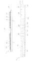
図1は、本発明の一実施例を示すものであって、図中符号1、1、1、1は、同一構造として構成されたインクを加圧する4個のアクチュエータユニットを、相互に一定の距離ΔLをずらせて後述する流路形成ユニット2に固定されている。
【0008】
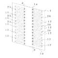
図2は、対向する圧力発生室の軸線の断面構造を、アクチュエータユニットと、流路形成ユニットとを分離して示すものであり、また図3は上述したアクチュエータユニットに形成されている圧力発生室の配列構造を示すものである。
【0009】
図中符号10は、スペーサで、深さ150μm程度の圧力発生室11、12を構成するの適した厚みを持つジルコニア(ZrO2)などのセラミックス板からなる基板に、圧力発生室11、12がノズル開口42、43の配列方向線に対してその長手方向の軸線が鋭角θとなり、かつ対向する内側の先端が主走査方向、つまりキャリッジの移動方向の同一線上に位置するように配列されて、インク滴の吐出タイミングをずらせることによりほぼ同一位置にドットの形成が可能なように構成されている。
【0010】
また上下の外壁1a、1bは、圧力発生室11、12の軸線にほぼ平行となるように形成されその厚みが可及的に薄く構成されている。
【0011】
このように圧力発生室11、12をその軸線方向がノズル開口の配列線に対して鋭角θとなるように傾斜させて配列することにより、直角に配列した従来の圧力発生室に比較して、長く構成することができて、特に高密度化により圧力発生室の幅を小さくせねばならない場合にあっても、インク滴を吐出させるに必要な圧力発生室の容積を十分に確保することができる。
【0012】
符号13は、弾性板で、スペーサ10と一体に焼成したときに十分な接合力を発揮するとともに、後述する圧電振動体14、15‥‥のたわみ振動により弾性変形する材料、例えば厚さ7μmのジルコニアの薄板で構成されている。
【0013】
14、15‥‥はそれぞれ前述の圧電振動体で、弾性板13の表面に形成されている下電極16、17の表面に、圧電材料のグリーンシートを各圧力発生室11、12に対向させて貼付し、その後に焼結し、さらに表面に上電極18、19を作り付けて構成されている。
【0014】
これら各部材10、13は、焼成により一体に固定されて前述のアクチュエータユニット1が構成されている。
【0015】
一方、図中符号2は、これらアクチュエータユニット1の固定基板を兼ねる前述の流路形成ユニットで、スペーサ10の他方の開口面を封止するようにアクチュエータユニット1が貼着、固定される蓋板を兼ねるインク供給口形成基板20と、リザーバ形成基板21と、ノズルプレート22を積層して構成されている。
【0016】
インク供給流路形成基板20は、厚さ100μmのジルコニアの薄板からなり、ノズルプレート22のノズル開口42、43と圧力発生室11、12とを接続する通孔23、24と、後述するリザーバ31、32(33、34)と圧力発生室11、12とを接続し、かつインク滴を吐出させることができる程度の流体抵抗を備えたインク供給口25、26とを穿設して構成されている。またリザーバ31、32(33、34)から離れた位置には、アクチュエータユニット1の一側の同一線上に並ぶように一定のピッチで4つのインク導入口38〜41が形成されている。
【0017】
リザーバ形成基板21は、リザーバ31、32(33、34)を構成するに適した例えば150μmのステンレス鋼などの耐蝕性を備えた板材に、一側に配置される圧力発生室全体にインクを供給するリザーバ31と、各アクチュエータユニットの他側に位置する圧力発生室12に独立してインクを供給する3つのリザーバ32(33、34)を形成するとともに、各圧力発生室11、12とノズル開口42、43とを接続するノズル連通孔27、28を形成して構成されている。
【0018】
他側に形成されたリザーバ32〜34は、それぞれ4つのアクチュエータユニット1、1、1、1の他側に上下に並ぶ複数の圧力発生室12を3等分した個数、この実施例では13個の圧力発生室12に連通するインク供給口26と連通できるサイズに形成されている。また各リザーバ31〜34は、インク供給口形成基板20に形成されたインク導入口38、39、40、41に連通され、リザーバ31には黒インク、また他のリザーバ32〜34にはイエロ、マゼンタ、及びシアンのインクが供給可能になっている。
【0019】
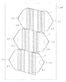
22は、前述のノズルプレートで、図5に示したようにアクチュエータユニット1、1、1、1にノズル連通孔23、27、及び24、28を介して連通し、かつ水平方向に並ぶ2つのものが同一線上に位置するように前述の圧力発生室11、12と同一のピッチで形成されている。なお、図中符号44〜47は、各リザーバ31〜34に形成された薄肉部からなるコンプライアンス付与領域を示す。
【0020】
この実施例において、各ノズル開口42、43の配列線が副走査方向、つまり紙送り方向に一致するようにキャリッジに搭載して、流路形成ユニット2の一側のリザーバ31にブラックのインクを、また他側の3つのリザーバ32、33、34にイエロ、シアン、マゼンタの各インクを供給する。そしてブラックのドット形成信号を各ユニット1、1、1、1の一側の圧電振動子14に、またカラードット形成信号を各ユニットの他側の圧電振動子15に供給する。
【0021】
すなわち、イエロのドット形成信号はリザーバ32に連通する圧力発生室12の圧電振動子15に、またマゼンタのドット形成信号はリザーバ33に連通する圧力発生室12の圧電振動子15に、さらにシアンのドット形成信号はリザーバ34に連通する圧力発生室12の圧電振動子15に供給する。
【0022】
これにより、黒のドット形成信号が印加されると、圧電振動子14が圧力発生室側にたわみ変位して一側の圧力発生室11のインクを加圧する。加圧された黒インクは流路形成ユニット2のノズル連通孔23、27を経由してノズル開口42からインク滴として吐出する。
【0023】
駆動信号が断たれて圧電振動子14が元の状態に戻ると、圧力発生室11が膨張する。これにより当該圧力発生室11とインク供給口25を介して接続するリザーバ31からインクが圧力発生室11に流れ込む。
【0024】
またカラーのドット形成信号が印加されると、他側の圧電振動子15が圧力発生室側にたわみ変位して他側の圧力発生室12のインクを加圧する。加圧されたカラーのインクは流路形成ユニット2のノズル連通孔24、28を経由してノズル開口43からインク滴として吐出する。
【0025】
駆動信号が断たれて圧電振動子15が元の状態に戻ると、圧力発生室12が膨張する。これにより当該圧力発生室12とインク供給口26を介して接続するリザーバ32〜34の色インクが圧力発生室12に流れ込む。
【0026】
ところで、カラーのインク滴を吐出するノズル開口43は、紙送り方向にほぼ13ドット分ずつ位置がずれているので、記録用紙の送り量を各色の記録幅に一致させることにより、同一位置に各色のドットを形成することができる。以下、このようにな過程を繰返して印刷を実行する。
【0027】
一方、テキストデータやモノクロ画像データを印刷する場合には、一側に上下に配列されている圧力発生室11の圧電振動子14にだけ駆動信号を供給すると、カラー印刷時の約3倍程度の紙送り方向の幅に印刷することができる。
【0028】
なお、この実施例においては4個のアクチュエータユニットを用いて記録ヘッドを構成する場合に例を採って説明したが、圧力発生室の数が極めて多く形成されたものや、また2個以上のアクチュエータを用いたものに対しても、一側よりのものをブラックに、また他側側のものを複数の領域に分割して、各領域に独立してインクを供給することができる構造であれば同様の作用を奏することは明らかである。
【0029】
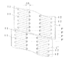
図6は本発明の他の実施例を示すものであって、図中符号1、1、1は、同一構造として構成されたインクを加圧する3個のアクチュエータユニットを、望ましくは各ユニット1の2列の圧力発生室の列の内、一方の圧力発生室の列が隣接する他のユニットの圧力発生室の列の一方に紙送り方向で同一線上に位置するように、紙送り方向に一定距離ずらせて後述する流路ユニット50に配置されている。
【0030】
流路ユニット50には、各アクチュエータユニットの圧力発生室と連通するノズル開口が、望ましくは各ユニット1に連通する2列のノズル開口列の内、一方のノズル開口列が隣接する他のユニットに連通するノズル開口列の一方に紙送り方向で同一線上に位置するように形成されている。また各アクチュエータユニット1、1、1の両側に位置するようにインク導入口51、52、53、54、55、56が形成され、各インク導入口51〜56に連通させて各アクチュエータユニット1、1、1毎の圧力発生室に連通するリザーバ57、58、59、60、61、62が形成されている。
【0031】
この実施例によれば、各インク導入口51〜56には、色の異なるインク、つまりブラック、イエロ、濃マゼンタ、淡マゼンタ、濃シアン、淡シアンのインクを外部から供給することにより、6色のインクによるカラー印刷が可能な記録装置を、主走査方向のサイズを可能限り抑えて構成することができる。
【0032】
なお、この実施例においてはアクチュエータユニットを3個使用する場合に例を採って説明したが、紙送り方向に配列するアクチュエータユニットの数をさらに増やすことにより、6色以上のインク滴を吐出させる記録ヘッドを構成することができる。
【0033】
なお、上述の実施例においては、圧力発生室を圧電振動子のたわみ振動により膨張、収縮させるユニットを複数使用した記録ヘッドに例を採って説明したが、縦振動モードの圧電振動子の一端を弾性板に当接させたり、また圧力発生室を発熱素子により加熱して加圧するものに適用しても同様の作用を奏する。
【0034】
また、上述の実施例においては圧力発生室をノズル開口の配列線に対して傾斜させたアクチュエータに例を採って説明したが、隣接領域でのノズル開口の配列ピッチを、アクチュエータユニット本来のノズル開口の配列ピッチと同一に維持できる構造のものにも適用できることは明らかである。
【図面の簡単な説明】
【図1】本発明の記録ヘッドの一実施例を示す正面図である。
【図2】同上インクジェット式記録ヘッドを、対向する圧力発生室の軸線の断面構造を、アクチュエータユニットと、流路形成ユニットとを分離して示す図である。
【図3】本発明のインクジェット式記録ヘッドを構成するアクチュエータユニットの一実施例を、弾性板を取り外して示す図である。
【図4】同上記録ヘッドに使用するノズルプレートの一実施例を示す図である。
【図5】隣接する2つの記録アクチュエータユニットの位置関係を示す図である。
【図6】本発明の他の実施例を、アクチュエータユニットとリザーバとの関係で示す図である。
【符号の説明】
1 アクチュエータユニット
2 流路形成ユニット
10 スペーサ
11、12 圧力発生室
13 弾性板
14、15 圧電振動子
20 インク供給口形成板
21 リザーバ形成板
22 ノズルプレート
23、24、27、28 ノズル連通孔
25、26 インク供給口
31〜34 リザーバ
38〜41 インク導入口
42、43 ノズル開口[0001]
TECHNICAL FIELD OF THE INVENTION
The present invention provides an ink jet recording head in which a plurality of actuator units for arranging a plurality of actuator units that pressurize ink in a pressure generation chamber to generate ink droplets are provided by providing pressure generation means in a partial area of the pressure generation chamber communicating with a nozzle opening. More specifically, the present invention relates to an ink jet recording head for full color printing constituted by combining a plurality of actuator units.
[0002]
[Prior art]
To cope with high-speed printing and high-density printing, the number of nozzle openings per print head has been increased. Sensitive to the effects of non-uniformity such as fluid resistance in the flow path of the pressure generating chambers and pressure generating chambers, it is required to form many nozzle openings and pressure generating chambers uniformly and with high accuracy. If a malfunction occurs in any one of the pressure generating means, the printing quality is extremely lowered and the printing head is no longer used, so that there is a problem that the production yield is extremely low.
[0003]
In order to solve such a problem, a plurality of recording heads each having a relatively small number of pressure generating means are arranged as a unit to constitute a recording head having a large number of nozzle openings arranged in the main scanning direction. According to this, the production yield as a unit is improved by the small number of pressure generating means constituting one unit, and as a result, a recording head having a large number of nozzle openings can be produced at a high yield. .
[0004]
[Problems to be solved by the invention]
However, since a gap is generated between the actuator units, the size of the recording head is increased. As a result, the recording apparatus is enlarged, and the print quality is also reduced due to a slight inclination when the recording head is attached to the recording apparatus. Since there is a large error in the dot formation position between the black nozzle opening and the color nozzle opening, which greatly affects the image quality, there is a problem that the assembling work becomes difficult.
The present invention has been made in view of such a problem, and an object of the present invention is to provide an ink jet recording apparatus that is particularly small in size using a plurality of recording actuator units and that can maintain the positional accuracy of nozzle openings. Is to provide a head.
[0005]
[Means for Solving the Problems]
In order to solve such a problem, in the present invention, a plurality of pressure generating chambers arranged in the paper feeding direction and formed in two rows in the moving direction of the carriage, and pressure generating means for pressing each of the pressure generating chambers are provided. an actuator unit with the arranged plural actuators to multiple paper feed way direction, and among the two rows pressure generating chambers in said plurality of actuator units, communicating the plurality of pressure generating chambers arranged in one row a common reservoir that is configured to, and so and a common flow passage unit having a nozzle opening communicating with the respective pressure generating chambers.
[0006]
[Action]
Since a plurality of actuator units are arranged in the paper feed direction and ink is supplied from a common reservoir, the size in the main scanning direction is reduced, and the size of the recording apparatus can be reduced .
[0007]
BEST MODE FOR CARRYING OUT THE INVENTION
Therefore, the details of the present invention will be described below based on the illustrated embodiment.
FIG. 1 shows an embodiment of the present invention. In the drawing,
[0008]
FIG. 2 shows the sectional structure of the axis of the opposing pressure generating chamber, with the actuator unit and the flow path forming unit separated from each other. FIG. 3 shows the pressure generating chamber formed in the above-described actuator unit. FIG.
[0009]
In the figure,
[0010]
The upper and lower outer walls 1a and 1b are formed so as to be substantially parallel to the axis of the
[0011]
By arranging the
[0012]
[0013]
Reference numerals 14 and 15} denote the above-described piezoelectric vibrators, respectively. A green sheet of a piezoelectric material is opposed to each of the
[0014]
These
[0015]
On the other hand,
[0016]
The ink supply flow
[0017]
The
[0018]
The number of
[0019]
[0020]
In this embodiment, the
[0021]
That is, the yellow dot forming signal is applied to the piezoelectric vibrator 15 of the
[0022]
Thus, when a black dot formation signal is applied, the piezoelectric vibrator 14 is flexed and displaced toward the pressure generating chamber to press the ink in the
[0023]
When the drive signal is cut off and the piezoelectric vibrator 14 returns to the original state, the
[0024]
When the color dot forming signal is applied, the other piezoelectric vibrator 15 is flexed and displaced toward the pressure generating chamber to press the ink in the other
[0025]
When the drive signal is cut off and the piezoelectric vibrator 15 returns to the original state, the
[0026]
By the way, since the positions of the
[0027]
On the other hand, when printing text data or monochrome image data, if a drive signal is supplied only to the piezoelectric vibrators 14 of the
[0028]
In this embodiment, the case where the recording head is constituted by using four actuator units has been described by way of example. However, an arrangement in which the number of pressure generating chambers is extremely large, or a case where two or more Also, if the structure is such that the ink from one side can be divided into black and the other side into a plurality of areas, ink can be supplied to each area independently. Obviously, it has a similar effect.
[0029]
FIG. 6 shows another embodiment of the present invention. In the drawing,
[0030]
In the flow path unit 50, the nozzle openings communicating with the pressure generating chambers of the actuator units are desirably provided. Of the two nozzle opening lines communicating with the
[0031]
According to this embodiment, inks of different colors, that is, black, yellow, dark magenta, light magenta, dark cyan, and light cyan inks are supplied to the respective ink introduction ports 51 to 56 from the outside, so that six colors are provided. The recording apparatus capable of performing color printing with the above ink can be configured with the size in the main scanning direction as small as possible.
[0032]
In this embodiment, an example has been described in which three actuator units are used. However, by further increasing the number of actuator units arranged in the paper feed direction, recording for ejecting ink droplets of six or more colors is performed. A head can be configured.
[0033]
In the above-described embodiment, an example has been described in which the recording head uses a plurality of units for expanding and contracting the pressure generating chamber by the flexural vibration of the piezoelectric vibrator. The same effect can be achieved by applying the present invention to a structure in which the pressure generating chamber is brought into contact with an elastic plate or the pressure generating chamber is heated by a heating element and pressurized.
[0034]
Further, in the above-described embodiment, an example is described in which the pressure generating chamber is inclined with respect to the arrangement line of the nozzle openings. However, the arrangement pitch of the nozzle openings in the adjacent region is changed to the original nozzle opening of the actuator unit. It is clear that the present invention can be applied to a structure that can maintain the same arrangement pitch as the above.
[Brief description of the drawings]
FIG. 1 is a front view showing an embodiment of a recording head according to the present invention.
FIG. 2 is a diagram showing the cross-sectional structure of the ink jet recording head in the axis line of the pressure generating chamber facing each other, in which an actuator unit and a flow path forming unit are separated.
FIG. 3 is a view showing one embodiment of an actuator unit constituting the ink jet recording head of the present invention, with an elastic plate removed.
FIG. 4 is a view showing one embodiment of a nozzle plate used in the recording head.
FIG. 5 is a diagram illustrating a positional relationship between two adjacent recording actuator units.
FIG. 6 is a diagram showing another embodiment of the present invention in relation to an actuator unit and a reservoir.
[Explanation of symbols]
DESCRIPTION OF
Claims (3)
前記複数のアクチュエータを複数紙送り方向に配置され、かつ前記複数のアクチュエータユニットにおける2列の圧力発生室のうち、一方の列に並ぶ複数の圧力発生室に連通するように構成された共通のリザーバと、前記各圧力発生室に連通するノズル開口とを備えた共通の流路ユニットと、
からなるインクジェット式記録ヘッド。An actuator unit including a plurality of pressure generating chambers arranged in the paper feed direction and formed in two rows in the moving direction of the carriage, and pressure generating means for pressurizing each of the pressure generating chambers;
A common reservoir in which the plurality of actuators are arranged in a plurality of paper feed directions and are configured to communicate with a plurality of pressure generating chambers arranged in one of the two rows of pressure generating chambers in the plurality of actuator units; And, a common flow path unit having a nozzle opening communicating with each of the pressure generating chambers,
An ink jet recording head comprising:
前記複数のアクチュエータを複数紙送り方向に配置され、かつ前記複数のアクチュエータユニットにおける2列の圧力発生室のうち、一方の列に並ぶ複数の圧力発生室を、前記紙送り方向に複数に分割して形成される各領域に連通するように構成された複数の分割リザーバと、前記他方の列に並ぶ複数の圧力発生室に連通するように構成された共通のリザーバと、前記各圧力発生室に連通するノズル開口とを備えた共通の流路ユニットと、
からなるインクジェット式記録ヘッド。An actuator unit including a plurality of pressure generating chambers arranged in the paper feed direction and formed in two rows in the moving direction of the carriage, and pressure generating means for pressurizing each of the pressure generating chambers;
The plurality of actuators are arranged in the plurality of paper feed directions, and among the two rows of pressure generation chambers in the plurality of actuator units, the plurality of pressure generation chambers arranged in one row are divided into a plurality of pieces in the paper feed direction. A plurality of divided reservoirs configured to communicate with each of the regions formed, and a common reservoir configured to communicate with the plurality of pressure generating chambers arranged in the other row; and A common flow path unit having a communicating nozzle opening,
An ink jet recording head comprising:
Priority Applications (9)
| Application Number | Priority Date | Filing Date | Title |
|---|---|---|---|
| JP3830897A JP3552011B2 (en) | 1997-02-06 | 1997-02-06 | Ink jet recording head |
| EP02025270A EP1285763B1 (en) | 1996-07-26 | 1997-07-28 | Ink jet type recording head |
| EP97112952A EP0820871B1 (en) | 1996-07-26 | 1997-07-28 | Ink jet type recording head |
| DE69734480T DE69734480T2 (en) | 1996-07-26 | 1997-07-28 | Ink jet type recording head |
| US08/901,787 US6042223A (en) | 1996-07-26 | 1997-07-28 | Ink jet type recording head |
| DE69718568T DE69718568T2 (en) | 1996-07-26 | 1997-07-28 | Ink jet type recording head |
| HK98102370A HK1003261A1 (en) | 1996-07-26 | 1998-03-20 | Ink jet type recording head |
| US09/100,138 US6220698B1 (en) | 1996-07-26 | 1998-06-19 | Ink jet type recording head |
| US09/507,680 US6371601B1 (en) | 1996-07-26 | 2000-02-22 | Ink jet type recording head |
Applications Claiming Priority (1)
| Application Number | Priority Date | Filing Date | Title |
|---|---|---|---|
| JP3830897A JP3552011B2 (en) | 1997-02-06 | 1997-02-06 | Ink jet recording head |
Publications (2)
| Publication Number | Publication Date |
|---|---|
| JPH10217452A JPH10217452A (en) | 1998-08-18 |
| JP3552011B2 true JP3552011B2 (en) | 2004-08-11 |
Family
ID=12521680
Family Applications (1)
| Application Number | Title | Priority Date | Filing Date |
|---|---|---|---|
| JP3830897A Expired - Lifetime JP3552011B2 (en) | 1996-07-26 | 1997-02-06 | Ink jet recording head |
Country Status (1)
| Country | Link |
|---|---|
| JP (1) | JP3552011B2 (en) |
Families Citing this family (12)
| Publication number | Priority date | Publication date | Assignee | Title |
|---|---|---|---|---|
| JP3775143B2 (en) * | 1998-12-24 | 2006-05-17 | セイコーエプソン株式会社 | Color printing apparatus and printing method using vertical array head, and recording medium |
| ATE407009T1 (en) * | 1998-12-24 | 2008-09-15 | Seiko Epson Corp | RECORDING HEAD OF AN INK JET TYPE |
| JP3707321B2 (en) * | 1998-12-24 | 2005-10-19 | セイコーエプソン株式会社 | Color printing apparatus and printing method using vertical array head, and print head therefor |
| JP2002052715A (en) * | 2000-05-29 | 2002-02-19 | Seiko Epson Corp | Ink jet recording head unit and image recorder comprising it |
| US6953241B2 (en) | 2001-11-30 | 2005-10-11 | Brother Kogyo Kabushiki Kaisha | Ink-jet head having passage unit and actuator units attached to the passage unit, and ink-jet printer having the ink-jet head |
| JP4147969B2 (en) * | 2002-02-20 | 2008-09-10 | ブラザー工業株式会社 | Ink jet head and ink jet printer having the same |
| JP3700702B2 (en) | 2003-01-06 | 2005-09-28 | セイコーエプソン株式会社 | Liquid jet head |
| JP4218385B2 (en) | 2003-03-24 | 2009-02-04 | 富士ゼロックス株式会社 | Ink jet recording head and ink jet recording apparatus |
| JP2004284253A (en) | 2003-03-24 | 2004-10-14 | Fuji Xerox Co Ltd | Inkjet recording head and inkjet recording device |
| JP4539549B2 (en) | 2005-12-09 | 2010-09-08 | ブラザー工業株式会社 | Inkjet head, inkjet head sub-assembly, inkjet head assembly, and inkjet printer |
| JP2015123690A (en) | 2013-12-26 | 2015-07-06 | セイコーエプソン株式会社 | Liquid ejecting device, self-sealing unit and liquid ejecting head |
| JP6823892B2 (en) * | 2016-09-01 | 2021-02-03 | キヤノン株式会社 | Liquid discharge head |
-
1997
- 1997-02-06 JP JP3830897A patent/JP3552011B2/en not_active Expired - Lifetime
Also Published As
| Publication number | Publication date |
|---|---|
| JPH10217452A (en) | 1998-08-18 |
Similar Documents
| Publication | Publication Date | Title |
|---|---|---|
| US20210008883A1 (en) | Ink-jet head having passage unit and actuator units attached to the passage unit, and ink-jet printer having the ink-jet head | |
| EP1034931B1 (en) | Ink jet type recording head | |
| EP1170127B1 (en) | Ink jet recording head | |
| JP3552011B2 (en) | Ink jet recording head | |
| US6371601B1 (en) | Ink jet type recording head | |
| US6033058A (en) | Actuator for an ink jet print head of the layered type with offset linear arrays of pressure generating chamber | |
| JP3329801B2 (en) | Ink jet recording head | |
| US7014294B2 (en) | Ink-jet head and ink-jet printer having ink-jet head | |
| EP1806229B1 (en) | Inkjet jet stack external manifold | |
| JP3610987B2 (en) | Multilayer ink jet recording head | |
| JP4324757B2 (en) | Inkjet printer head | |
| JP3702919B2 (en) | Inkjet recording head | |
| JPH07276630A (en) | Ink jet print head and ink jet printer | |
| JPH1178013A (en) | Ink jet line type recording head | |
| JP4042084B2 (en) | Inkjet recording head | |
| JP4385667B2 (en) | An ink jet recording head and a printing apparatus having the ink jet recording head. | |
| JP3578196B2 (en) | Ink jet recording head | |
| JP3680947B2 (en) | Multilayer ink jet recording head | |
| EP0985536B1 (en) | Ink jet type recording head | |
| JPH0872259A (en) | Ink jet recording apparatus | |
| JP3890852B2 (en) | Inkjet recording head and inkjet recording apparatus | |
| JPH09156096A (en) | Ink jet printer | |
| JP2003334947A (en) | Inkjet printer head | |
| JP2001199065A (en) | Ink jet recording head and ink jet recorder | |
| JP2000263786A (en) | Ink jet recording head and ink jet recording apparatus |
Legal Events
| Date | Code | Title | Description |
|---|---|---|---|
| TRDD | Decision of grant or rejection written | ||
| A01 | Written decision to grant a patent or to grant a registration (utility model) |
Free format text: JAPANESE INTERMEDIATE CODE: A01 Effective date: 20040407 |
|
| A61 | First payment of annual fees (during grant procedure) |
Free format text: JAPANESE INTERMEDIATE CODE: A61 Effective date: 20040420 |
|
| R150 | Certificate of patent or registration of utility model |
Free format text: JAPANESE INTERMEDIATE CODE: R150 |
|
| FPAY | Renewal fee payment (event date is renewal date of database) |
Free format text: PAYMENT UNTIL: 20080514 Year of fee payment: 4 |
|
| FPAY | Renewal fee payment (event date is renewal date of database) |
Free format text: PAYMENT UNTIL: 20090514 Year of fee payment: 5 |
|
| FPAY | Renewal fee payment (event date is renewal date of database) |
Free format text: PAYMENT UNTIL: 20100514 Year of fee payment: 6 |
|
| FPAY | Renewal fee payment (event date is renewal date of database) |
Free format text: PAYMENT UNTIL: 20110514 Year of fee payment: 7 |
|
| FPAY | Renewal fee payment (event date is renewal date of database) |
Free format text: PAYMENT UNTIL: 20120514 Year of fee payment: 8 |
|
| FPAY | Renewal fee payment (event date is renewal date of database) |
Free format text: PAYMENT UNTIL: 20130514 Year of fee payment: 9 |
|
| FPAY | Renewal fee payment (event date is renewal date of database) |
Free format text: PAYMENT UNTIL: 20140514 Year of fee payment: 10 |
|
| S531 | Written request for registration of change of domicile |
Free format text: JAPANESE INTERMEDIATE CODE: R313531 |
|
| R350 | Written notification of registration of transfer |
Free format text: JAPANESE INTERMEDIATE CODE: R350 |
|
| EXPY | Cancellation because of completion of term |