JP3775143B2 - Color printing apparatus and printing method using vertical array head, and recording medium - Google Patents
Color printing apparatus and printing method using vertical array head, and recording medium Download PDFInfo
- Publication number
- JP3775143B2 JP3775143B2 JP34185999A JP34185999A JP3775143B2 JP 3775143 B2 JP3775143 B2 JP 3775143B2 JP 34185999 A JP34185999 A JP 34185999A JP 34185999 A JP34185999 A JP 34185999A JP 3775143 B2 JP3775143 B2 JP 3775143B2
- Authority
- JP
- Japan
- Prior art keywords
- sub
- dot
- dots
- nozzle
- scanning
- Prior art date
- Legal status (The legal status is an assumption and is not a legal conclusion. Google has not performed a legal analysis and makes no representation as to the accuracy of the status listed.)
- Expired - Fee Related
Links
Images


Landscapes
- Ink Jet (AREA)
- Facsimile Scanning Arrangements (AREA)
- Fax Reproducing Arrangements (AREA)
Description
【0001】
【発明の属する技術分野】
この発明は、複数色のドットを形成するための印刷ヘッドを用いてカラー印刷を行う技術に関する。
【0002】
【従来の技術】
印刷ヘッドが主走査方向と副走査方向に走査しながらドットの記録を行う印刷装置としては、シリアルスキャン型プリンタやドラムスキャン型プリンタ等がある。この種のプリンタ、特にインクジェットプリンタ、における画質向上のための技術の一つとして、米国特許第4,198,642号や特開昭53−2040号公報等に開示されている「インターレース方式」と呼ばれる技術がある。
【0003】
図25は、インターレース方式の一例を示す説明図である。この明細書では、印刷方式を規定するパラメータとして、以下のものを用いている。
【0004】
N:ノズル個数[個],
k:ノズルピッチ[ドット],
s:スキャン繰り返し数,
D:ノズル密度[個/インチ],
L:副走査送り量[ドット]または[インチ],
w:ドットピッチ[インチ]。
【0005】
ノズル個数N[個]は、ドットの形成に使用されるノズルの個数である。図25の例ではN=3である。ノズルピッチk[ドット]は、印刷ヘッドにおけるノズルの中心点間隔が、印刷画像のピッチ(ドットピッチw)の何個分であるかを示している。図25の例では、k=2である。スキャン繰り返し回数s[回]は、何回の主走査で各主走査ラインをドットで埋めつくすか、を示す回数である。なお、以下では主走査ラインを「ラスタ」と呼ぶ。図25の例では、1回の主走査で各ラスタが埋めつくされているので、s=1である。後述するように、sが2以上の時には、主走査方向に沿って間欠的にドットが形成される。ノズル密度D[個/インチ]は、印刷ヘッドのノズルアレイにおいて、1インチ当たり何個のノズルが配列されているかを示している。副走査送り量L[ドット]または[インチ]は、1回の副走査で移動する距離を示している。ドットピッチw[インチ]は、印刷画像におけるドットのピッチである。なお、一般に、w=1/(D・k)、k=1/(D・w)が成立する。
【0006】
図25において、2桁の数字を含む丸は、それぞれドットの記録位置を示している。図25左下の凡例に示されているように、丸の中の2桁の数字の中で、左側の数字はノズル番号を示しており、右側の数字は記録順番(何回目の主走査で記録されたか)を示している。
【0007】
図25に示すインターレース方式は、印刷ヘッドのノズルアレイの構成と、副走査の方法とに特徴がある。即ち、インターレース方式では、隣り合うノズルの中心点間隔を示すノズルピッチkは2以上の整数に設定され、かつ、ノズル個数Nとノズルピッチkとが互いに素の関係にある整数に選ばれる。また、副走査送り量Lは、N/(D・k)で与えられる一定の値に設定される。
【0008】
このインターレース方式には、ノズルのピッチやインク吐出特性等のばらつきを、印刷画像上で分散させることができるという利点がある。従って、ノズルのピッチや吐出特性にばらつきがあっても、これらの影響を緩和して画質を向上させることができるという効果を奏する。
【0009】
カラーインクジェットプリンタにおける画質改善を目指した別の技術として、特開平3−207665号公報や特公平4−19030号公報等に開示された「オーバーラップ方式」又は「マルチスキャン方式」と呼ばれる技術がある。
【0010】
図26は、オーバーラップ方式の一例を示す説明図である。このオーバーラップ方式では、8個のノズルを2組のノズル群に分類している。1組目のノズル群は、ノズル番号(丸の中の左側の数字)が偶数である4個のノズルで構成されており、2組目のノズル群は、ノズル番号が奇数である4個のノズルで構成されている。1回の主走査では、各組のノズル群をそれぞれ間欠的タイミングで駆動することにより、主走査方向に(s−1)ドットおきにドットを形成する。図26の例では、s=2なので、1ドットおきにドットが形成される。また、各組のノズル群は、主走査方向にそれぞれ異なる位置にドット形成するように、それぞれの駆動タイミングが制御されている。すなわち、図26に示すように、第1のノズル群のノズル(ノズル番号8,6,4,2)と、第2のノズル群のノズル(ノズル番号7,5,3,1)とは、記録位置が主走査方向に1ドットピッチ分だけずれている。そして、このような主走査を複数回行い、その都度各ノズル群の駆動タイミングをずらすことにより、ラスタ上の全ドットの形成を完成させる。
【0011】
オーバーラップ方式においても、インターレース方式と同様に、ノズルピッチkは2以上の整数に設定される。ただし、ノズル個数Nとノズルピッチkとは互いに素の関係には無く、この代わりに、ノズル個数Nをスキャン繰り返し数sで割った値N/sと、ノズルピッチkとが互いに素の関係にある整数に選ばれる。また、副走査送り量Lは、N/(s・D・k)で与えられる一定の値に設定される。なお、「整数A,Bが互いに素」とは、整数A,Bが1以外の公約数を有さないことを意味している。
【0012】
このオーバーラップ方式では、各ラスタ上のドットが同一のノズルで記録されず、複数のノズルを用いて記録される。従って、ノズルの特性(ピッチや吐出特性等)にばらつきがある場合にも、特定のノズルの特性の影響が1つのラスタの全体に及ぶことを防止でき、この結果、画質を向上させることができる。
【0013】
【発明が解決しようとする課題】
ところで、画質を向上させる点で好ましい印刷方式は、印刷ヘッドにおけるノズルアレイの配列に応じて異なる。従って、特定の印刷ヘッドに関して、画質を向上させるための印刷方式を設定することは容易でない場合がある。
【0014】
この発明は、従来技術における上述の課題を解決するためになされたものであり、特定の印刷ヘッドに関して高画質が得られる技術を提供することを目的とする。
【0015】
【課題を解決するための手段およびその作用・効果】
上述の課題の少なくとも一部を解決するため、本発明では、次の特徴を有する印刷ヘッドを用いる。i)イエロードットを形成するためのイエロードット形成要素群を含みそれぞれ異なるインクのドットを形成するための複数の有彩色ドット形成要素群が副走査方向に沿って配列された第1のドット形成要素アレイを有する。ii)第1のドット形成要素アレイと並列に形成され、ブラックドットを形成するための複数のドット形成要素を含む第2のドット形成要素アレイを有する。iii)複数の有彩色ドット形成要素群は、互いに等しい数のドット形成要素をそれぞれ備えている。iv)第2のドット形成要素アレイは、複数の有彩色ドット形成要素群に含まれるドット形成要素と同じ副走査位置に配置された複数のドット形成要素を少なくとも有している。また、印刷ヘッドにおいては、カラー印刷の際に前記印刷媒体上の任意の位置において、イエロードットがブラックドットとマゼンタドットとシアンドットよりも後に形成されるように前記複数のドット形成要素が配列されている。さらに、副走査駆動部は、比較的高い精度で副走査送りを行う第1の副走査駆動機構と、前記第1の副走査駆動機構による副走査送りが終了した後に、比較的低い精度で副走査送りを行う第2の副走査駆動機構と、を備える。
【0016】
カラー印刷の際には、各有彩色ドット形成要素群について、互いに等しい数のN個(Nは2以上の整数)のドット形成要素をそれぞれ使用して前記印刷媒体上にドットを形成するとともに、使用されるドット形成要素でそれぞれ構成される使用ドット形成要素群同士の間の間隔を、副走査方向に沿ったドット形成要素のピッチのM倍(Mは2以上の整数)であって、かつ、(N×n+1)倍以外の値(Nは使用ドット形成要素数、nは1以上の任意の整数)に設定する。また、前記第2のドット形成要素アレイに含まれる複数のドット形成要素の中で、それぞれN個のドット形成要素で構成されるj組(jは1以上の整数)のブラックドット形成要素群を使用してブラックドットを形成する。さらに、前記第1と第2の副走査駆動機構の両方を使用して前記比較的高い精度で副走査送りを実行している間に、前記印刷媒体上における前記ブラックドットとマゼンタドットとシアンドットの形成を完了する。また、前記印刷媒体の後端が前記第1の副走査駆動機構の挟持点を通過した後に前記第2の副走査駆動機構のみによって副走査送りが実行されるときに、前記ブラックドットとマゼンタドットとシアンドットの形成が完了しており前記イエロードットの形成が完了していない領域内において前記第1のドット形成要素アレイに含まれるドット形成要素の中では前記イエロードット形成要素群に含まれるドット形成要素のみを用いて印刷を実行する。
【0017】
上記の本発明では、カラー印刷に用いるブラックドット形成要素群の組数jを所望の値に設定することにより、好ましい画質を得ることができる。すなわち、本発明では、特定の印刷ヘッドに関して高画質が得られる印刷を実行することができる。また、使用ドット形成要素群同士の間の間隔を、副走査方向に沿ったドット形成要素のピッチのM倍(Mは2以上の整数)であって、かつ、(N×n+1)倍以外の値(Nは使用ドット形成要素の数、nは1以上の任意の整数)に設定することによって、副走査方向に沿って隣接する使用ドット形成要素群に関して副走査送りの誤差累積位置がなるべく一致しないようにすることができるので、画質が向上する。
【0018】
整数jが1のときに、ブラックドットに関しては、第1のドット形成要素アレイ内の複数の有彩色ドット形成要素群の中で最も早く印刷媒体上でのドット形成が実行可能となる特定の有彩色ドット形成要素群において使用されるドット形成要素と同じ副走査位置に存在するドット形成要素のみを用いてブラックドットの形成を実行するようにすることが好ましい。
【0019】
こうすれば、印刷媒体上の各位置において、ブラックドットが他の色のドットよりも早い時期に形成されるので、ブラックドットの滲みを防止して、彩度の高いカラー画像を得ることができる。
【0020】
また、整数jが2以上のときに、ブラックドットに関しては、主走査ライン上の互いに異なるj種類のドット位置をj組のブラックのドット形成要素群の記録対象としてブラックドットの形成をそれぞれ実行することが好ましい。
【0021】
こうすれば、ブラックドットに関しては、各主走査ライン上のドットがj個の異なるドット形成要素を用いて形成される。従って、各ドット形成要素によるドット形成位置が副走査方向にズレている場合にも、j個のドット形成要素のズレが平均化されるので画質が向上する。
【0022】
なお、第1と第2のドット形成要素アレイは、同一のアクチュエータ内に形成されていることが好ましい。
【0023】
こうすれば、ドット形成要素同士を精度良く配置することが可能なので、画質を向上させることができる。
【0024】
本発明の具体的な態様としては、印刷装置、印刷方法、記録媒体等の種々の態様を取りうる。
【0025】
【発明の実施の形態】
A.装置の全体構成:
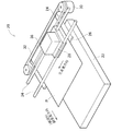
次に、本発明の実施の形態を実施例に基づき説明する。図1は、本発明の一実施例としてのカラーインクジェットプリンタ20の主要な構成を示す概略斜視図である。このプリンタ20は、用紙スタッカ22と、図示しないステップモータで駆動される紙送りローラ24と、プラテン板26と、キャリッジ28と、ステップモータ30と、ステップモータ30によって駆動される牽引ベルト32と、キャリッジ28のためのガイドレール34とを備えている。キャリッジ28には、多数のノズルを備えた印刷ヘッド36が搭載されている。
【0026】
印刷用紙Pは、用紙スタッカ22から紙送りローラ24によって巻き取られて、プラテン板26の表面上を副走査方向へ送られる。キャリッジ28は、ステップモータ30により駆動される牽引ベルト32に牽引されて、ガイドレール34に沿って主走査方向に移動する。主走査方向は、副走査方向に垂直である。
【0027】
図2は、プリンタ20の電気的な構成を示すブロック図である。プリンタ20は、ホストコンピュータ100から供給された信号を受信する受信バッファメモリ50と、印刷データを格納するイメージバッファ52と、プリンタ20全体の動作を制御するシステムコントローラ54とを備えている。システムコントローラ54には、キャリッジモータ30を駆動する主走査駆動ドライバ61と、紙送りモータ31を駆動する副走査駆動ドライバ62と、印刷ヘッド36を駆動するヘッド駆動ドライバ63とが接続されている。
【0028】
ホストコンピュータ100のプリンタドライバ(図示せず)は、ユーザの指定した印刷方式(後述する)に基づいて、印刷動作を規定する各種のパラメータ値を決定する。このプリンタドライバは、さらに、これらのパラメータ値に基づいて、その印刷方式で印刷を行うための印刷データを生成して、プリンタ20に転送する。転送された印刷データは、一旦、受信バッファメモリ50に蓄えられる。プリンタ20内では、システムコントローラ54が、受信バッファメモリ50から印刷データの中から必要な情報を読取り、これに基づいて、各ドライバ61,62,63に対して制御信号を送る。
【0029】
イメージバッファ52には、受信バッファメモリ50で受信された印刷データを色成分毎に分解して得られた複数の色成分のイメージデータが格納される。ヘッド駆動ドライバ63は、システムコントローラ54からの制御信号に従って、イメージバッファ52から各色成分のイメージデータを読出し、これに応じて印刷ヘッド36に設けられた各色のノズルアレイを駆動する。
【0030】
B.印刷ヘッドの構成:
図3は、印刷ヘッド36の下部に設けられたアクチュエータ40の底面に形成されたノズルの配列を示す説明図である。アクチュエータ40の底面には、それぞれ副走査方向に沿った一直線上に配列されたカラーノズル列とブラックノズル列とが形成されている。なお、「アクチュエータ」とは、ノズルと、インク吐出のための駆動素子(例えばピエゾ素子やヒータ)とを含むインク吐出機構を意味する。通常、1つのアクチュエータのノズル部分は、セラミックス成形によって一体として形成される。1つのアクチュエータ内に2列のノズル列を形成するようにすれば、ノズル同士を精度良く配置することが可能なので、画質を向上させることができる。なお、本明細書においては、「ノズル列」を「ノズルアレイ」とも呼ぶ。
【0031】
ブラックノズル列は、48個のノズル#K1〜#K48を有している。これらのノズル#K1〜#K48は、副走査方向に沿って一定のノズルピッチkで配置されている。このノズルピッチkは、6ドットである。但し、ノズルピッチkは、印刷媒体P上のドットピッチに、2以上の任意の整数を乗じた値に設定することができる。
【0032】
カラーノズル列は、イエロー用ノズル群40Yと、マゼンタ用ノズル群40Mと、シアン用ノズル群40Cとを含んでいる。なお、この明細書では、有彩色インク用のノズル群を「有彩色ノズル群」とも呼ぶ。イエロー用ノズル群40Yは、15個のノズル#Y1〜#Y15を有しており、これらの15個のノズルのピッチは、ブラックノズル列のノズルピッチkと同じである。これは、マゼンタ用ノズル群40Mやシアン用ノズル群40Cも同じである。なお、イエロー用ノズル群40Yの下端のノズル#Y15と、マゼンタ用ノズル群40Mの上端のノズル#M1との間の「×」マークは、その位置にノズルが形成されていないことを示してしている。従って、イエロー用ノズル群40Yの下端のノズル#Y15と、マゼンタ用ノズル群40Mの上端のノズル#M1との間隔は、ノズルピッチkの2倍である。これは、マゼンタ用ノズル群40Mの下端のノズル#M15と、シアン用ノズル群40Cの上端のノズル#C1との間隔についても同様である。換言すれば、イエロー用とマゼンタ用とシアン用の各ノズル群同士の間隔は、ノズルピッチkの2倍の値に設定されている。
【0033】
カラーノズル群40Y、40M、40Cのノズルは、ブラックノズル列40Kのノズルと同じ副走査位置に配置されている。但し、ブラックノズル列40Kの48個のノズル#K1〜#K48の中で、16番目と32番目と48番目のノズル#K16,#K32,#K48に対しては、対応する位置に有彩色インク用のノズルが設けられていない。
【0034】
印刷時には、キャリッジ28(図1)とともに印刷ヘッド36が主走査方向に移動している間に、各ノズルからインク滴が吐出される。但し、印刷方式によっては、すべてのノズルが常に使用されるとは限らず、一部のノズルのみが使用される場合もある。
【0035】
C.副走査駆動機構の構成:
図4は、印刷用紙Pを搬送する副走査駆動部を示す概念図である。副走査駆動部は、給紙側に備えられた第1の副走査駆動機構25と、排紙側に備えられた第2の副走査駆動機構27とを有している。第1の副走査駆動機構25は、給紙ローラ25aと従動ローラ25bとで構成されている。第2の副走査駆動機構27は、排紙ローラ27aとギザローラ27bとで構成される。これらのローラ25a,25b,27a,27bは、紙送りモータ31(図2)の回転が、図示しないギヤトレインを介して伝達されることによって駆動される。印刷の開始時には、印刷用紙Pは給紙側(図4の右側)から第1の副走査駆動機構25のローラ25a,25bに挟持されて、両ローラの回転により搬送される。印刷用紙Pの先端が第2の副走査駆動機構27のローラ27a,27bに挟持されると、これらのローラによっても排紙側に送られるようになる。また、印刷用紙Pの後端が第1の副走査駆動機構25の挟持点(ローラ25a,25bによって挟持される点)を通過した後は、第2の副走査駆動機構27のみによって印刷用紙Pが搬送される。印刷用紙Pには、プラテン26上で印刷ヘッド36により画像が記録される。
【0036】
なお、このプリンタにおいては、紙送りの精度は、給紙側の第1の副走査駆動機構25の方が、排紙側の第2の副走査駆動機構27よりも高い。従って、印刷用紙Pの後端が第1の副走査駆動機構25の挟持点を通過した後に、第2の副走査駆動機構27のみによって紙送りが行われる場合には、送り量の精度が第1の副走査駆動機構25によって搬送される場合に比べて低くなる。
【0037】
図4において、符号「40W」は、副走査方向に沿ったノズル列の全幅を示しており、符号「WLP」は、イエロー用ノズル群40Yの幅を示している。なお、この幅WLPは、後述する低精度領域の幅に相当する。符号「WB」は、第1の副走査駆動機構25の挟持点から、ノズル列の後端までの距離を示している。なお、本明細書において、印刷用紙やノズル列の先端と後端は、紙送り方向(副走査方向)に従って定義されている。また、紙送り方向や副走査方向は、副走査時に、印刷用紙Pがプリンタ20に対して相対的に移動してゆく方向として定義されている。なお、「先端」を「上端」と呼び、また、「後端」を「下端」と呼ぶこともある。
【0038】
D.一般的な印刷方式の基本的条件:
本発明の実施例における印刷方式を説明する前に、以下ではまず、一般的な印刷方式に要求される基本的な条件について説明する。なお、以下の説明においては、「印刷方式」のことを「ドット記録方式」と呼んでいる。
【0039】
図5は、スキャン繰り返し数sが1のときの一般的なドット記録方式の基本的条件を示すための説明図である。図5(A)は、4個のノズルを用いた場合の副走査送りの一例を示しており、図5(B)はそのドット記録方式のパラメータを示している。図5(A)において、数字を含む実線の丸は、各副走査送り後の4個のノズルの副走査方向の位置を示している。丸の中の数字0〜3は、ノズル番号を意味している。4個のノズルの位置は、1回の主走査が終了する度に副走査方向に送られる。但し、実際には、副走査方向の送りは紙送りモータ31(図2)によって用紙を移動させることによって実現されている。
【0040】
図5(A)の左端に示すように、この例では副走査送り量Lは4ドットの一定値である。従って、副走査送りが行われる度に、4個のノズルの位置が4ドットずつ副走査方向にずれてゆく。スキャン繰り返し数sが1の場合には、各ノズルは、それぞれのラスタ上のすべてのドット(「画素」とも呼ぶ)を記録可能である。図5(A)の右端には、各ラスタ上のドットを記録するノズルの番号が示されている。なお、ノズルの副走査方向位置を示す丸印から右方向(主走査方向)に伸びる破線で描かれたラスタでは、その上下のラスタの少なくとも一方が記録できないので、実際にはドットの記録が禁止される。一方、主走査方向に伸びる実線で描かれたラスタは、その前後のラスタがともにドットで記録され得る範囲である。このように実際に記録を行える範囲を、以下では有効記録範囲(有効印刷範囲)または「印刷領域」と呼ぶ。
【0041】
図5(B)には、このドット記録方式に関する種々のパラメータが示されている。ドット記録方式のパラメータには、ノズルピッチk[ドット]と、使用ノズル個数N[個]と、スキャン繰り返し数sと、実効ノズル個数Neff [個]と、副走査送り量L[ドット]とが含まれている。
【0042】
図5の例では、ノズルピッチkは3ドットである。使用ノズル個数Nは4個である。なお、使用ノズル個数Nは、実装されている複数個のノズルの中で実際に使用されるノズルの個数である。スキャン繰り返し数sは、一回の主走査において(s−1)ドットおきに間欠的にドットを形成することを意味している。従って、スキャン繰り返し数sは、各ラスタ上のすべてのドットを記録するために使用されるノズルの数にも等しい。図5の場合には、スキャン繰り返し数sは1である。実効ノズル個数Neff は、使用ノズル個数Nをスキャン繰り返し数sで割った値である。この実効ノズル個数Neff は、一回の主走査で記録され得るラスタの正味の本数を示しているものと考えることができる。実効ノズル数Neff の意味についてはさらに後述する。
【0043】
図5(B)の表には、各副走査送り毎に、副走査送り量Lと、その累計値ΣLと、各副走査送り後のノズルのオフセットFとが示されている。ここで、オフセットFとは、副走査送りが行われていない最初のノズルの周期的な位置(図5では4ドットおきの位置)をオフセット0の基準位置と仮定した時に、副走査送り後のノズルの位置が基準位置から副走査方向に何ドット離れているかを示す値である。例えば、図5(A)に示すように、1回目の副走査送りによって、ノズルの位置は副走査送り量L(4ドット)だけ副走査方向に移動する。一方、ノズルピッチkは3ドットである。従って、1回目の副走査送り後のノズルのオフセットFは1である(図5(A)参照)。同様にして、2回目の副走査送り後のノズルの位置は、初期位置からΣL=8ドット移動しており、そのオフセットFは2である。3回目の副走査送り後のノズルの位置は、初期位置からΣL=12ドット移動しており、そのオフセットFは0である。3回の副走査送りによってノズルのオフセットFは0に戻るので、3回の副走査を1サイクルとして、このサイクルを繰り返すことによって、有効記録範囲のラスタ上のすべてのドットを記録することができる。
【0044】
上記の例からも解るように、ノズルの位置が初期位置からノズルピッチkの整数倍だけ離れた位置にある時には、オフセットFはゼロである。また、オフセットFは、副走査送り量Lの累計値ΣLをノズルピッチkで割った余り(ΣL)%kで与えられる。ここで、「%」は、除算の余りをとることを示す演算子である。なお、ノズルの初期位置を周期的な位置と考えれば、オフセットFは、ノズルの初期位置からの位相のずれ量を示しているものと考えることもできる。
【0045】
スキャン繰り返し数sが1の場合には、有効記録範囲においてラスタの抜けや重複が無いようにするためには、以下のような条件を満たすことが必要である。
【0046】
条件c1:1サイクルの副走査送り回数は、ノズルピッチkに等しい。
【0047】
条件c2:1サイクル中の各回の副走査送り後のノズルのオフセットFは、0〜(k−1)の範囲のそれぞれ異なる値となる。
【0048】
条件c3:副走査の平均送り量(ΣL/k)は、使用ノズル数Nに等しい。換言すれば、1サイクル当たりの副走査送り量Lの累計値ΣLは、使用ノズル数Nとノズルピッチkとを乗算した値(N×k)に等しい。
【0049】
上記の各条件は、次のように考えることによって理解できる。隣接するノズルの間には(k−1)本のラスタが存在するので、1サイクルでこれら(k−1)本のラスタ上で記録を行ってノズルの基準位置(オフセットFがゼロの位置)に戻るためには、1サイクルの副走査送りの回数はk回となる。1サイクルの副走査送りがk回未満であれば、記録されるラスタに抜けが生じ、一方、1サイクルの副走査送りがk回より多ければ、記録されるラスタに重複が生じる。従って、上記の第1の条件c1が成立する。
【0050】
1サイクルの副走査送りがk回の時には、各回の副走査送りの後のオフセットFの値が0〜(k−1)の範囲の互いに異なる値の時にのみ、記録されるラスタに抜けや重複が無くなる。従って、上記の第2の条件c2が成立する。
【0051】
上記の第1と第2の条件を満足すれば、1サイクルの間に、N個の各ノズルがそれぞれk本のラスタの記録を行うことになる。従って、1サイクルではN×k本のラスタの記録が行われる。一方、上記の第3の条件c3を満足すれば、図5(A)に示すように、1サイクル後(k回の副走査送り後)のノズルの位置が、初期のノズル位置からN×kラスタ離れた位置に来る。従って、上記第1ないし第3の条件c1〜c3を満足することによって、これらのN×k本のラスタの範囲において、記録されるラスタに抜けや重複を無くすることができる。
【0052】
図6は、スキャン繰り返し数sが2以上の場合の一般的なドット記録方式の基本的条件を示すための説明図である。スキャン繰り返し数sが2以上の場合には、同一のラスタがs本の異なるノズルで記録される。以下では、スキャン繰り返し数sが2以上のドット記録方式を「オーバーラップ方式」と呼ぶ。
【0053】
図6に示すドット記録方式は、図5(B)に示すドット記録方式のパラメータの中で、スキャン繰り返し数sと副走査送り量Lとを変更したものである。図6(A)からも解るように、図6のドット記録方式における副走査送り量Lは2ドットの一定値である。但し、図6(A)においては、奇数回目の副走査送りの後のノズルの位置を、菱形で示している。図6(A)の右端に示すように、奇数回目の副走査送りの後に記録される画素位置は、偶数回目の副走査送りの後に記録される画素位置と、主走査方向に1ドット分だけずれている。従って、同一のラスタ上の複数のドットは、異なる2つのノズルによってそれぞれ間欠的に記録されることになる。例えば、有効記録範囲内の最上端のラスタは、1回目の副走査送り後に2番のノズルで1ドットおきに間欠的に記録された後に、4回目の副走査送り後に0番のノズルで1ドットおきに間欠的に記録される。一般に、オーバーラップ方式では、各ノズルは、1回の主走査中に1ドット記録した後に(s−1)ドット記録を禁止するように、間欠的なタイミングでノズルが駆動される。
【0054】
なお、オーバーラップ方式では、同一ラスタを記録する複数のノズルの主走査方向の位置が互いにずれていればよいので、各主走査時における実際の主走査方向のずらし量は、図6(A)に示すもの以外にも種々のものが考えられる。例えば、1回目の副走査送りの後には主走査方向のずらしを行わずに丸で示す位置のドットを記録し、4回目の副走査送りの後に主走査方向のずらしを行なって菱形で示す位置のドットを記録するようにすることも可能である。
【0055】
図6(B)の表の最下段には、1サイクル中の各回の副走査後のオフセットFの値が示されている。1サイクルは6回の副走査送りを含んでおり、1回目から6回目までの各回の副走査送りの後のオフセットFは、0〜2の範囲の値を2回ずつ含んでいる。また、1回目から3回目までの3回の副走査送りの後のオフセットFの変化は、4回目から6回目までの3回の副走査送りの後のオフセットFの変化と等しい。図6(A)の左端に示すように、1サイクルの6回の副走査送りは、3回ずつの2組の小サイクルに区分することができる。このとき、副走査送りの1サイクルは、小サイクルをs回繰り返すことによって完了する。
【0056】
一般に、スキャン繰り返し数sが2以上の整数の場合には、上述した第1ないし第3の条件c1〜c3は、以下の条件c1’〜c3’のように書き換えられる。
【0057】
条件c1’:1サイクルの副走査送り回数は、ノズルピッチkとスキャン繰り返し数sとを乗じた値(k×s)に等しい。
【0058】
条件c2’:1サイクル中の各回の副走査送り後のノズルのオフセットFは、0〜(k−1)の範囲の値であって、それぞれの値がs回ずつ繰り返される。
【0059】
条件c3’:副走査の平均送り量{ΣL/(k×s)}は、実効ノズル数Neff (=N/s)に等しい。換言すれば、1サイクル当たりの副走査送り量Lの累計値ΣLは、実効ノズル数Neff と副走査送り回数(k×s)とを乗算した値{Neff ×(k×s)}に等しい。
【0060】
上記の条件c1’〜c3’は、スキャン繰り返し数sが1の場合にも成立する。従って、条件c1’〜c3’は、スキャン繰り返し数sの値に係わらず、ドット記録方式に関して一般的に成立する条件である。すなわち、上記の3つの条件c1’〜c3’を満足すれば、有効記録範囲において、記録されるドットに抜けや重複が無いようにすることができる。但し、オーバーラップ方式(スキャン繰り返し数sが2以上の場合)を採用する場合には、同じラスタを記録するノズルの記録位置を互いに主走査方向にずらすという条件も必要である。
【0061】
なお、記録方式によっては、部分的なオーバーラップが行われる場合もある。「部分的なオーバーラップ」とは、1つのノズルで記録されるラスタと、複数のノズルで記録されるラスタとが混在しているような記録方式のことを言う。このような部分的なオーバーラップを用いた記録方式においても、実効ノズル数Neff を定義することができる。例えば、4個のノズルのうちで、2個のノズルが協力して同一のラスタを記録し、残りの2個のノズルはそれぞれ1本のラスタを記録するような部分的なオーバーラップ方式では、実効ノズル数Neff は3個である。このような部分的なオーバーラップ方式の場合にも、上述した3つの条件c1’〜c3’が成立する。
【0062】
なお、実効ノズル数Neff は、一回の主走査で記録され得るラスタの正味の本数を示しているものと考えることもできる。例えば、スキャン繰り返し数sが2の場合には、2回の主走査で使用ノズル数Nと等しい本数のラスタを記録することができるので、一回の主走査で記録することができるラスタの正味の本数は、N/s(すなわちNeff )に等しい。
【0063】
E.印刷方式の第1実施例:
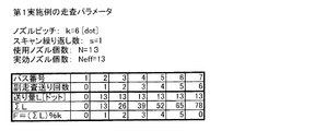
図7は、本発明の第1実施例の印刷方式における走査パラメータを示す説明図である。第1実施例では、ノズルピッチkが6ドット、スキャン繰り返し数sが1、使用ノズル個数Nが13、実効ノズル個数Neff が13である。
【0064】
図7の下部の表には、1回目から7回目までの各パスに関するパラメータが示されている。なお、本明細書では、1回の主走査のことを「パス」とも呼んでいる。この表では、各パスに関して、そのパスの直前に実行される副走査の送り量Lと、その累積値ΣLと、オフセットFと、が示されている。副走査送り量Lは13ドットの一定値である。このように、副走査送り量Lが一定値である印刷方式(走査方式)を「定則送り」と呼ぶ。なお、第1実施例の走査パラメータは、上述した条件c1’〜c3’を満足している。
【0065】
図8は、第1実施例において使用されるノズルを示す説明図である。図8のアクチュエータ40は図3に示すものと同じであるが、第1実施例では一部のノズルのみが使用される。図8において、第1実施例で使用されるノズルは白丸で示されており、一方、使用されないノズルは黒丸で示されている。すなわち、有彩色インクについては、各色の15個のノズルのうちの最初の13個のノズルがそれぞれ使用される。また、ブラックインクについては、シアン用の使用ノズル#C1〜#C13と同じ副走査位置にある13個のノズルのみが使用される。このように、4つのインクについて、それぞれ同じ数のノズルを使用すれば、各用のノズルに共通する走査パラメータに従って走査を実行することによって、各インクのドットを、抜けや重複無く形成することができる。
【0066】
なお、本明細書では、使用されるノズルで構成される各インク用のノズル群を「使用ノズル群」とも呼ぶ。また、アクチュエータ40に設けられている各インク用のノズル群を「実装ノズル群」とも呼ぶ。
【0067】
各インクの使用ノズルとしては、ノズルピッチkで連続して並んでいるものが選択される。また、イエロー用の使用ノズル群の下端のノズル#Y13と、マゼンタ用の使用ノズル群の上端のノズル#M1との間隔は、4k(すなわち24ドット)である。同様に、マゼンタ用の使用ノズル群の下端のノズル#M13と、シアン用の使用ノズル群の上端のノズル#C1との間隔も、4kである。
【0068】
図9は、第1実施例の各パスにおいて有効記録範囲内の各ラスタラインを記録するノズルを示す説明図である。パス1では、シアン用の3つのノズル#C11〜#C13が、1番目と7番目と13番目の有効ラスタライン上のドット記録をそれぞれ実行する。なお、「有効ラスタライン」とは、有効記録範囲内のラスタラインのことを意味する。なお、図9では、ノズル番号の先頭の符号「#」が省略されている。また、斜線が付されているノズルは不使用ノズルを示している。符号「×」は、隣接する実装ノズル群の中間のノズルの存在しない位置を示している。
【0069】
パス2では、印刷用紙上におけるアクチュエータ40の記録対象位置が、パス1から副走査方向に13ドット分移動する。本実施例ではノズルピッチkは6なので、この副走査送り後のノズル位置のオフセットF(送り量Lの累積値ΣLをkで除した余り)は1ドットである。従って、パス2においては、見かけ上、パス1で記録対象となったラスタラインよりも1本下のラスタラインが記録対象となるように見える。もちろん、実際には、13本下のラスタラインが記録対象となっている。なお、第1実施例では、副走査送り量Lが13ドットの一定値なので、副走査送りが1回行われる毎に、記録対象となるラスタラインの位置が1本ずつ下に移動するように見える。
【0070】
シアンインクに関しては、以下に説明するように、6番目と7番目のラスタラインの間の位置Cmis において副走査送り誤差の累積値が最も大きくなる。6番目のラスタラインはパス6において記録され、一方、7番目のラスタラインはパス1において記録される。従って、7番目のラスタラインを記録するパス1と、6番目のラスタラインを記録するパス6との間には、副走査送りが5回行われる。従って、6番目と7番目のラスタラインの間には、5回分の副走査送り誤差が累積される。同様に、12番目と13番目のラスタラインの間にも、シアンインクに関して5回分の副走査送り誤差が累積される。
【0071】
上述と同様な考察により、マゼンタインクに関しては、7番目と8番目のラスタラインの間の位置Mmis において、副走査送り誤差の累積値が比較的大きくなることが解る。また、イエローインクに関しては、9番目と10番目のラスタラインの間の位置Ymis において、副走査送り誤差の累積値が比較的大きくなる。なお、以下では、副走査送り誤差の累積値が比較的大きな位置を、「誤差累積位置」と呼ぶ。
【0072】
以上の説明から理解できるように、第1実施例では、誤差累積位置が各有彩色インク毎に異なり、一致することが無い。誤差累積位置では、バンディング(主走査方向に伸びる筋状の画質劣化部分)が発生しやすい傾向にある。しかし、本実施例によれば、誤差累積位置が各有彩色インク毎に異なっているので、これらの位置におけるバンディングを目立たなくすることができる。
【0073】
図10は、第1比較例において使用されるアクチュエータを示す説明図である。このアクチュエータ40’は、各有彩色ノズル群40Y’,40M’,40C’をそれぞれ13個のノズルで構成している。また、各有彩色ノズル群40Y’,40M’,40C’の端部のノズル同士の間隔は、ノズルピッチkと等しい。すなわち、図10のアクチュエータ40’では、第1実施例で使用されていた各有彩色インク用の13個のノズルが、ノズルピッチkで連続して配列されている。ブラック用ノズル群40K’も、ノズルピッチkで配列された39個のノズルで構成されている。第1比較例では、このようなアクチュエータ40’を用い、図7に示した第1実施例の走査パラメータと同じ走査パラメータに従って印刷を実行する。
【0074】
図11は、第1比較例の各パスにおいて有効記録範囲内の各ラスタラインを記録するノズルを示す説明図である。第1比較例では、3色の有彩色インクに関する誤差累積位置Cmis ,Mmis ,Ymis が、6番目と7番目のラスタラインの間の位置、および、12番目と13番目のラスタラインの間の位置で一致している。このような場合には、バンディングが目立ちやすく、画質が劣化する可能性が高い。
【0075】
図8と図10に示す使用ノズルを比較すれば解るように、第1実施例と第1比較例の違いは、各使用ノズル群の間隔だけである。すなわち、第1実施例では、使用色ノズル群の間の間隔が、ノズルピッチkの4倍の値4kに設定されており、一方、第1比較例では使用ノズル群の間の間隔が、ノズルピッチkと同じ値に設定されている。このような使用ノズル群の間の間隔の違いが、図9と図11に示すような誤差累積位置Cmis ,Mmis ,Ymis の発生位置の違いとして現れていることが理解できる。
【0076】
副走査方向に沿って隣接するノズル群に関して誤差累積位置がなるべく一致しないようにするためには、一般に、隣接する使用ノズル群の間の間隔が、ノズルピッチkのM倍(Mは2以上の整数)となるように、使用ノズルを選択することが好ましい。
【0077】
但し、副走査方向に沿って隣接する使用ノズル群の間の間隔は、更に、以下のように設定することが好ましい。図12は、図5に示した印刷方式における等価的なノズル位置を示す説明図である。図5でも説明したように、スキャン繰り返し数sが1の時には、1サイクルの走査はk回の副走査送りを含む。従って、1サイクル分の副走査送りにおけるノズル群の移動量はN×kラスタである。図12には、1サイクル目から3サイクル目までの各サイクルにおけるノズル群の初期位置が示されている。これらの3つのノズル群位置からは、同じ記録動作が実行されるので、これらの位置は互いに等価である。1サイクル目の初期位置における下端のノズルと、2サイクル目の初期位置における上端のノズルとの間隔は、kドットである。また、1サイクル目の初期位置における下端のノズルと、3サイクル目の初期位置における上端のノズルとの間隔は、(N×k+k)ドットである。図示は省略されているが、1サイクル目の初期位置における下端のノズルと、4サイクル目の初期位置における上端のノズルとの間隔は、(2×N×k+k)ドットであることが解る。一般には、1サイクル目の初期位置のノズル群の下端のノズルと、他の等価なノズル群の上端のノズルとの間の間隔は、(N×n+1)kドットと書き表せる。ここで、nは0以上の任意の整数である。
【0078】
図12に示すような等価的なノズル群位置に、異なるインクの使用ノズル群を配置してしまうと、それらのインクに関する誤差累積位置は互いに一致する。このような場合を避けるために、隣接する使用ノズル群の間の間隔は、(N×n+1)kドット以外の値(Nは使用ノズル数、nは1以上の任意の整数)に設定することが好ましい。ここで、nを0以上ではなく1以上としたのは、上述したように隣接する使用ノズル群の間の間隔をノズルピッチkのM倍(Mは2以上の整数)に設定すると、n=0の場合が除外されるからである。
【0079】
上述した第1実施例は、さらに以下のような特徴も有している。前述した図8から解るように、ブラックノズル列40Kは、主走査時にカラーノズル列に先行するので、カラー印刷の際には、ブラックドットが他のインクのドットよりも先に印刷用紙上に形成される。また、カラーノズル列に関しては、副走査方向に沿って、シアン用ノズル群40C,マゼンタ用ノズル群40M,イエロー用ノズル群40Yの順に配列されており、有彩色のドットはこの順序で形成される。さらに、ブラック用の使用ノズル群としては、副走査方向の後端に存在するシアン用の使用ノズル群と同じ副走査位置に存在するノズルのみが使用される。
【0080】
以上のようなアクチュエータ40の特徴から、第1実施例のカラー印刷においては、次のような種々の利点が生じる。第1の利点は、ブラックドットが、他のインクのドットよりも先に形成される点である。仮に他のインクのドットの後にブラックドットを形成すると、ブラックインクが滲んでしまい、カラー画像の彩度が低下してしまう傾向にある。特に、ブラックインクとイエローインクとが互いに滲むと、彩度が顕著に低下する傾向にある。そこで、図8のように使用ノズル群を選択することによって、印刷領域内の任意の位置において、ブラックドットを他のインクのドットよりも先に形成するようにすれば、カラー画像の彩度を向上させることができる。
【0081】
第2の利点は、印刷領域内の任意の位置において、イエロードットが他のインクのドットの後に形成される点である。図8から理解できるように、印刷用紙Pが副走査方向に搬送されると、印刷領域PA内の任意の位置においては、まず、ブラックドットとシアンドットがこの順に形成され、次に、マゼンタドットが形成され、最後に、イエロードットが形成される。ところで、図4に示したように、印刷用紙Pの後端が第1の副走査駆動機構25の挟持点(ローラ25a,25bの接点)を通過した後では、副走査送りは比較的低精度の第2の副走査駆動機構27のみで行われる。この結果、以下に説明するように、イエロー用ノズル群40Yの幅WLPと同じ幅を有する低精度領域においてイエロードットを形成する際には、副走査送りが比較的低精度で行われることにある。
【0082】
図13は、印刷用紙Pの後端に存在する低精度領域LPAとアクチュエータ40との関係を示す説明図である。印刷領域PAの後端に存在する低精度領域LPAにおいてイエロードットが形成されるときには、第2の副走査駆動機構27によって比較的低い精度で副走査送りが行われる。ここで、「低精度領域LPA」とは、副走査送り精度が低い領域、という意味である。なお、低精度領域LPAの幅は、副走査方向に沿って測ったイエロー用ノズル群40Yの幅に等しい。
【0083】
図13の時点では、低精度領域LPA内におけるブラックドットとマゼンタドットとシアンドットの形成は終了している。従って、図13の時点以降では、低精度領域LPAにおいてイエロードットのみが形成される。しかし、一般に、イエロードットは、他の3色のドットよりも目立たないという性質がある。このため、副走査送り精度が低く、イエロードットの位置が多少ずれても、画質をあまり劣化させることはない。すなわち、本実施例では、第2の副走査駆動機構27のみによって副走査送りが行われるときに、低精度領域LPAにおいてイエロードットのみを形成するので、低精度領域LPAにおいても画質があまり劣化しないという利点がある。
【0084】
ところで、印刷用紙の先端近傍や後端近傍では、印刷領域の中間部分とは異なる印刷方式で印刷が実行されるのが普通である。この明細書では、印刷領域の後端近傍における印刷処理を「後端処理」または「下端処理」と呼ぶ。また、印刷領域の中間部分における印刷処理を「中間処理」と呼ぶ。下端処理では、副走査送り精度を過度に低下させないようにするために、印刷領域の中間部分よりも少ない送り量で副走査送りが実行される。下端処理としては、例えば、本出願人により開示された特開平7−242025号公報に記載された技術がある。この公報の図9には、印刷領域の中間部分においてインターレース方式による印刷が行われ、印刷領域の下端近傍においては「微小送り」(1ドットの副走査送り)による下端処理が行われることが示されている。
【0085】
本実施例では、低精度領域LPAにおいてイエロードットを形成する際には、下端処理を行わずに、中間処理と同じ送り量で副走査送りを実行する。具体的には、図7に示した副走査送り量をそのまま用いて低精度領域LPAにおけるイエロードットの形成を行う。換言すれば、第2の副走査駆動機構27のみで副走査送りが実行されるときにも、第1の副走査駆動機構25による副走査送りが実行されるときと同じ送り量で副走査送りを実行する。こうすれば、副走査送りの制御が簡単になるという利点がある。なお、イエロードットは他のドットに比べて目立たないので、下端処理を行わなくても、あまり画質を低下させることは無い。
【0086】
F.印刷方式の第2実施例:
図14は、本発明の第2実施例の印刷方式における走査パラメータを示す説明図である。第2実施例では、ノズルピッチkが6ドット、スキャン繰り返し数sが1、使用ノズル個数Nが15、実効ノズル個数Neff が15である。
【0087】
図14の下部の表には、1回目から7回目までの各パスに関するパラメータが示されている。副走査送り量Lとしては、14,15,16ドットの3種類の異なる値の配列が使用されている。このように、副走査送り量Lとして異なる複数の値の配列を用いる印刷方式(走査方式)を「変則送り」と呼ぶ。なお、第2実施例の走査パラメータも、上述した条件c1’〜c3’を満足している。
【0088】
図15は、第2実施例において使用されるノズルを示す説明図である。図15のアクチュエータ40は図3に示すものと同じである。有彩色インクについては、各色の15個のノズルのすべてが使用される。また、ブラックインクについては、シアン用の使用ノズル#C1〜#C15と同じ副走査方向位置にある15個のノズルのみが使用される。従って、イエロー用の使用ノズル群の下端のノズル#Y15と、マゼンタ用の使用ノズル群の上端のノズル#M1との間隔は、2kである。同様に、マゼンタ用の使用ノズル群の下端のノズル#M15と、シアン用の使用ノズル群の上端のノズル#C1との間隔も、2kである。
【0089】
第2実施例も、前述した第1実施例と同様に、カラー印刷において次のような種々の利点を有している。第1の利点は、ブラックドットが他のインクのドットよりも先に形成されるので、彩度の高いカラー画像を印刷できる点である。第2の利点は、低精度領域LPA(図13)においてイエロードットのみが形成されるので、副走査送り精度が低下しても画質があまり劣化しない点である。なお、第1実施例と同様に、第2の副走査駆動機構27のみで副走査送りが実行されるときに、第1の副走査駆動機構25による副走査送りが実行されるときと同じ送り量(すなわち図14に示す送り量)で副走査送りを実行するようにしてもよい。
【0090】
図16は、第2実施例の各パスにおいて有効記録範囲内の各ラスタラインを記録するノズルを示す説明図である。第2実施例では変則送りを利用しているので、パス毎のノズル群の位置は第1実施例ほどの規則性は無い。従って、副走査送り累積誤差は、第1実施例よりも少ないという利点がある。
【0091】
第2実施例は、さらに以下に説明するように、副走査送りの誤差累積位置が、各使用ノズル群同士で常時一致することはない、という利点も有している。シアンに関しては、副走査送り回数の差が最も大きいのは2番目と3番目のラスタラインの間であり、これらの副走査送り回数の差は4である。すなわち、シアンに関しては、2番目と3番目のラスタラインの間に誤差累積位置Cmis が存在する。マゼンタとイエローについても、2番目と3番目のラスタラインの間に誤差累積位置Mmis ,Ymis が存在する。ところで、シアンとマゼンタに関しては、その次の累積誤差位置Cmis ,Mmis は、8番目と9番目のラスタラインの間に存在する。一方、イエローに関しては、その次の累積誤差位置Ymis は、7番目と8番目のラスタラインの間に存在する。
【0092】
このように、第2実施例では、3つの使用ノズル群に関する累積誤差位置Cmis ,Mmis ,Ymis が、常時一致することは無い。このため、3つの使用ノズル群に関する累積誤差位置Cmis ,Mmis ,Ymis が常時一致するような場合に比べて、副走査送りの累積誤差によるバンディングの発生を緩和することができる。
【0093】
図17は、第2比較例において使用されるアクチュエータを示す説明図である。図17のアクチュエータ40”は、各有彩色ノズル群40Y”,40M”,40C”をそれぞれ15個のノズルで構成している。また、各有彩色ノズル群40Y”,40M”,40C”の端部のノズル同士の間隔は、ノズルピッチkと等しい。また、ブラック用ノズル群40”は、45個のノズルで構成されている。第2比較例では、このようなアクチュエータ40”を用い、図14に示した第2実施例の走査パラメータと同じ走査パラメータに従って印刷を実行する。
【0094】
図18は、第2比較例の各パスにおいて有効記録範囲内の各ラスタラインを記録するノズルを示す説明図である。第2比較例では、3色の有彩色インクに関する誤差累積位置Cmis ,Mmis ,Ymis が、2番目と3番目のラスタラインの間と、8番目と9番目のラスタラインの間と、14番目と15番目のラスタラインの間との間に存在する。すなわち、第2実施例では、3色のインクに関する誤差累積位置Cmis ,Mmis ,Ymis が常に一致しており、6ドットの間隔で(すなわちノズルピッチkの間隔で)、誤差累積位置Cmis ,Mmis ,Ymis が繰り返し現れる。このように、各有彩色ノズル群に関する誤差累積位置Cmis ,Mmis ,Ymis が常に一致していると、バンディングが目立ち易い。
【0095】
図15と図17とを比較すれば解るように、第2実施例と第2比較例の違いは、各使用ノズル群の間隔だけである。すなわち、第2実施例では、使用ノズル群同士の間隔が、ノズルピッチkの2倍の値2kに設定されており、一方、第2比較例では使用ノズル群同士の間隔が、ノズルピッチkと同じ値に設定されている。このような使用ノズル群の間の間隔の違いが、図16と図18に示すような誤差累積位置Cmis ,Mmis ,Ymis の発生位置の違いとして現れている。
【0096】
これから解るように、第2実施例も第1実施例と同様に、隣接する使用ノズル群の間の間隔がノズルピッチkのM倍(Mは2以上の整数)となるように、使用ノズルが選択されている。また、隣接する使用ノズル群の間の間隔は、(N×n+1)kドット以外の値(Nは使用ノズル数、nは1以上の任意の整数)に設定されている。
【0097】
なお、図15から理解できるように、第2実施例では、アクチュエータ40に設けられているすべての有彩色インク用ノズルを使用している。本実施例に使用したアクチュエータ40では、各インクの実装ノズル群の間隔をノズルピッチkの2倍の値に設定しているので、すべての有彩色インク用ノズルを用いても、副走査送りの誤差累積位置が、各有彩色ノズル群同士で常時一致することはない。従って、アクチュエータ40に設けられているノズルの中の可能な限り多数の有彩色インク用ノズルを用いて、高画質な印刷を行うことができるという利点がある。
【0098】
なお、一般には、副走査方向に沿って配列されている実装ノズル群同士の間隔(すなわち、各インク用の実装ノズル群の端部のノズル同士の間隔)は、ノズルピッチkのm倍(mは2以上の整数)となるように設定されていることが好ましい。こうすれば、上述した理由により、可能な限り多数のノズルを用いて高画質な印刷を行うことが可能である。
【0099】
なお、副走査方向に沿って配列されている実装ノズル群同士の間隔が、ノズルピッチkに等しく設定されていてもよい。この場合には、各実装ノズル群の中のいくつかのノズルが不使用とすれば、第1実施例や第2実施例と同様の使用ノズル群を構成することが可能である。
【0100】
G.他の実施例:
図19は、第3実施例の使用ノズルを示す説明図である。第3実施例は、図8に示した第1実施例とはブラックの使用ノズル群が異なるだけであり、ハードウェア構成は、第1実施例と同である。また、有彩色ノズルに関しては、図7に示した第1実施例と同じ走査パラメータがそのまま使用される。ブラックノズルに関しては、後述するように、ノズルピッチkと副走査送り量Lは第1実施例と同じであるが、スキャン繰り返し数sと、使用ノズル数Nと、実効ノズル数Neff とは異なる値が使用される。
【0101】
図19では、ブラックズル列40Kの複数のノズルが、3つの有彩色ノズル群40C,40M,40Yに対応する3つのブラックノズル群G1,G2,G3に分類されている。第1のノズル群G1は、シアン用ノズル群40Cと同じ副走査位置に存在する15個のノズル#K33〜#K47で構成されている。第2のノズル群G2は、マゼンタ用ノズル群40Mと同じ副走査位置に存在する15個のノズル#K17〜#K31で構成されている。第3のノズル群G3は、イエロー用ノズル群40Yと同じ副走査位置に存在する15個のノズル#K1〜#K15で構成されている。なお、カラーノズル列において欠落しているノズル位置に対応する3つのブラックノズル#K16,#K32,#K48は、3つのブラックノズル群G1,G2,G3のいずれにも属していない。
【0102】
第3実施例では、2つのノズル群G1,G2から選択された合計26個のノズルが使用されている。すなわち、第1のノズル群G1の中で、シアン用の13個の使用ノズル#C1〜#C13と同じ副走査位置にあるノズル#K33〜#K45が選択されて使用されている。また、第2のノズル群G2の中で、マゼンタ用の13個の使用ノズル#M1〜#M13と同じ副走査位置にあるノズル#K17〜#K29が選択されて使用されている。
【0103】
第1のノズル群G1の使用ノズル#K33〜#K45は、各ラスタライン上の奇数画素位置を対象としてブラックドットの形成を実行する。また、第2のノズル群G2内の使用ノズル#K17〜#K29は、各ラスタライン上の偶数画素位置を対象としてブラックドットの形成を実行する。従って、ブラックドットに関しては、スキャン繰り返し数sが2、使用ノズル数Nが26、実効ノズル数Neff が13である。換言すれば、ブラックドットに関しては、2つのノズル群G1,G2を用いてオーバーラップ方式に従って印刷が実行される。
【0104】
このように、ブラックドットに関してオーバーラップ方式でドットの形成を行うようにすれば、ブラック用ノズルの特性(ピッチや吐出特性等)にばらつきがある場合にも、特定のノズルの特性の影響が1つのラスタの全体に及ぶことを防止できる。この結果、バンディング(主走査方向に伸びる筋状の画質劣化部分)を緩和して、画質を向上させることができる。
【0105】
図20は、第4実施例の使用ノズルを示す説明図である。第4実施例では、ブラック用の使用ノズルが、第3実施例から追加されている。すなわち、第4実施例では、第1と第2のノズル群G1,G2の使用ノズルは図19に示した第3実施例と同じであり、これに加えて、第3のノズル群G3の中でイエロー用の13個の使用ノズル#Y1〜#Y13と同じ副走査位置にあるノズル#K1〜#K13が選択されて使用されている。
【0106】
第4実施例では、第1ないし第3のノズル群G1〜G3の使用ノズルは、各ラスタライン上の互いに異なる特定の画素位置%1,%2,%3をそれぞれ記録対象としてブラックドットの形成を実行する。ここで、画素位置%i(iは1〜3の整数)は、画素座標を3で割った余りがiである画素位置(「ドット位置」とも呼ぶ)を意味している。従って、ブラックドットに関しては、スキャン繰り返し数sが3、使用ノズル数Nが39、実効ノズル数Neff が13である。換言すれば、ブラックドットに関しては、3つのノズル群G1,G2,G3を用いてオーバーラップ方式に従って印刷が実行される。
【0107】
第4実施例では、スキャン繰り返し数が第3実施例よりも大きいので、バンディングを緩和して画質を向上させる効果が第3実施例よりも顕著である。
【0108】
なお、前述した第2実施例に対しても、図19および図20に示す実施例と同様に、ブラックドットに関しては、オーバーラップ方式に従ってドット形成を行うことが可能である。
【0109】
上述した種々の実施例から理解できるように、一般には、有彩色ノズル群がそれぞれN個のノズルを使用するときに、ブラックノズルに関して、それぞれN個のノズルで構成されるj組(jは1以上の整数)のブラックノズル群を使用してカラー印刷を行うことが可能である。このとき、各ラスタラインは互いに異なるj種類の画素位置に分類され、各ブラックノズル群はその中の1種類の画素位置を記録対象位置としてドットの形成を実行する。
【0110】
なお、上記実施例のアクチュエータ40を用いた場合には、上記整数jは、有彩色ノズル群の群数3以下の値になる。しかし、ブラックノズル列がもっと多くのノズルを有する場合には、整数jを、有彩色ノズル群の群数よりも大きな値に設定することも可能である。
【0111】
各ラスタライン上の画素位置の分類方法としては、上述した図19,図20に示したもの以外の種々のものを採用することができる。例えば、隣接する2画素の単位で分類を行うようにしてもよい。一般には、ラスタライン上のすべての画素位置を規則的に複数のグループに分類すればよい。
【0112】
H.アクチュエータの変形例:
図21は、アクチュエータの第1変形例を示す説明図である。このアクチュエータ43は、図3に示す実施例のアクチュエータ40のカラーノズル列とブラックノズル列40Kとを、それぞれ千鳥状に2列に配列したものである。例えば、ブラックノズル列40Kでは、奇数番目のノズル#K1,#K3…#K47が左側の列に配置され、偶数番目のノズル#K2,#K4…#K48は右側の列に配置されている。3つの有彩色ノズル群40Y,40M,40Cにおいても同様に、それぞれ千鳥状にノズルが配列されている。このように、千鳥状にノズルが配列されている場合にも、3つの有彩色ノズル群40Y,40M,40Cが、副走査方向に沿って一直線上に配列されていることには変わりはない。すなわち、この明細書では、「複数のノズル群が副走査方向に沿って一直線上に配列されている」という文言は、ノズル群同士が全体として一直線上に沿って配列されていればよく、各ノズル群を構成する複数のノズルは必ずしも一直線上に配列されている必要は無い。
【0113】
図22は、アクチュエータの第2変形例を示す説明図である。この第2変形例では、カラーノズル列のみを含む第1のアクチュエータ44aと、ブラックノズル列40Kのみを含む第2のアクチュエータ44bと、の2つのアクチュエータが用いられる。各色のノズル群は、図21と同様に、千鳥状に配列されている。図21と実質的に異なる点は、カラーインク用ノズル群がそれぞれ16個のノズルを有しており、各カラーインク用ノズル群の間隔がノズルピッチkに等しい、という点だけである。なお、図22では、ノズルピッチkは4ドット分に設定されている。カラー印刷の際に、各カラーインク用ノズル群の16個のノズルが全部使用されるときには、ブラックノズル列の下端の16個のノズル(#K33〜#K48)が使用される。
【0114】
図23は、アクチュエータの第3変形例を示す説明図である。このアクチュエータ45は、3つのカラーノズル列と、1つのブラックノズル列とを含んでいる。第1のカラーノズル列は、イエロー用ノズル群40Yとマゼンタ用ノズル群40Mとで構成されている。第2のカラーノズル列は、淡マゼンタ用ノズル群40LMとシアン用ノズル群40Cとで構成されている。第3のカラーノズル列は、淡シアン用ノズル群40LCと淡ブラック用ノズル群40LKとで構成されている。なお、「淡ブラック」とは、黒ではなくグレーであることを意味している。「淡マゼンタ」とは、マゼンタとほぼ同じ色相を有し、濃度が低いインクを意味している。「淡シアン」も同様である。
【0115】
各ノズル群は、副走査方向に沿って一直線状に配列されているが、図21や図22のように千鳥状に配列することも可能である。ブラックノズル列40Kは、48個のノズルを有している。また、ブラックノズル列40K以外の各ノズル群は、24個のノズルをそれぞれ有している。カラー印刷の際に、各カラーインク用ノズル群の24個のノズルが全部使用されるときには、ブラックノズル列の下端の24個のノズル(#K25〜#K48)が使用される。
【0116】
このアクチュエータ45を用いてカラー印刷を行う際には、ドットが形成される順番は、ブラック、淡ブラック、淡シアン、シアン、マゼンタ、淡マゼンタ、マゼンタ、イエローの順である。すなわち、このアクチュエータ45によっても、ブラックドットを他のインクのドットよりも先に印刷用紙上に形成することができ、また、イエロードットを、他のインクのドットの後に形成することができる。
【0117】
図24は、アクチュエータの第4変形例を示す説明図である。このアクチュエータ46と、図23に示すアクチュエータ45との差違は、ブラックノズル列40Kとイエロー用ノズル群40Y以外のノズル群の位置だけである。このアクチュエータ46を用いてカラー印刷を行う場合にも、ブラックドットを他のインクのドットよりも先に印刷用紙上に形成することができ、また、イエロードットを、他のインクのドットの後に形成することができる。
【0118】
図23,図24の例からも理解できるように、カラーノズル列を2列以上設けることも可能である。また、ブラックノズル列を2列以上設けることも可能である。すなわち、本発明は、印刷ヘッドが少なくとも1つのカラーノズル列と、少なくとも1つのブラックノズル列とを有する場合に適用可能である。
【0119】
なお、この発明は上記の実施例や実施形態に限られるものではなく、その要旨を逸脱しない範囲において種々の態様において実施することが可能であり、例えば次のような変形も可能である。
【0120】
(1)上記実施例では、主走査方向の往路でのみドットの形成を行う単方向印刷を行うものとしていたが、本発明は、主走査方向の往路と復路の双方でドットの形成を行う双方向印刷にも適用可能である。
【0121】
(2)印刷装置によっては、主走査方向のドットピッチ(記録解像度)と、副走査方向のドットピッチとを異なる値に設定できるものがある。この場合には、主走査方向に関係するパラメータ(例えばラスタライン上の画素ピッチ)は、主走査方向のドットピッチによって定義され、一方、副走査方向に関係するパラメータ(例えばノズルピッチkや副走査送り量L)は、副走査方向のドットピッチによって定義される。
【0122】
(3)この発明はドラムスキャンプリンタにも適用可能である。尚、ドラムスキャンプリンタでは、ドラム回転方向が主走査方向、キャリッジ走行方向が副走査方向となる。また、この発明は、インクジェットプリンタのみでなく、一般に、複数のドット形成要素アレイを有する印刷ヘッドを用いて印刷媒体の表面に記録を行う印刷装置に適用することができる。ここで、「ドット形成要素」とは、インクジェットプリンタにおけるインクノズルのように、ドットを形成するための構成要素を意味する。このような印刷装置としては、例えばファクシミリ装置や、コピー装置などがある。
【0123】
(4)上記実施例において、ハードウェアによって実現されていた構成の一部をソフトウェアに置き換えるようにしてもよく、逆に、ソフトウェアによって実現されていた構成の一部をハードウェアに置き換えるようにしてもよい。例えば、システムコントローラ54(図2)の機能の一部をホストコンピュータ100が実行するようにすることもできる。
【0124】
このような機能を実現するコンピュータプログラムは、フロッピディスクやCD−ROM等の、コンピュータ読み取り可能な記録媒体に記録された形態で提供される。ホストコンピュータ100は、その記録媒体からコンピュータプログラムを読み取って内部記憶装置または外部記憶装置に転送する。あるいは、通信経路を介してプログラム供給装置からホストコンピュータ100にコンピュータプログラムを供給するようにしてもよい。コンピュータプログラムの機能を実現する時には、内部記憶装置に格納されたコンピュータプログラムがホストコンピュータ100のマイクロプロセッサによって実行される。また、記録媒体に記録されたコンピュータプログラムをホストコンピュータ100が直接実行するようにしてもよい。
【0125】
この明細書において、ホストコンピュータ100とは、ハードウェア装置とオペレーションシステムとを含む概念であり、オペレーションシステムの制御の下で動作するハードウェア装置を意味している。コンピュータプログラムは、このようなホストコンピュータ100に、上述の各部の機能を実現させる。なお、上述の機能の一部は、アプリケーションプログラムでなく、オペレーションシステムによって実現されていても良い。
【0126】
なお、この発明において、「コンピュータ読み取り可能な記録媒体」とは、フレキシブルディスクやCD−ROMのような携帯型の記録媒体に限らず、各種のRAMやROM等のコンピュータ内の内部記憶装置や、ハードディスク等のコンピュータに固定されている外部記憶装置も含んでいる。
【図面の簡単な説明】
【図1】本発明の一実施例としてのカラーインクジェットプリンタ20の主要な構成を示す概略斜視図。
【図2】プリンタ20の電気的な構成を示すブロック図。
【図3】アクチュエータ40の底面に形成されたノズルの配列を示す説明図。
【図4】印刷用紙Pを搬送する副走査駆動機構を示す側断面図。
【図5】スキャン繰り返し数sが1のときの一般的なドット記録方式の基本的条件を示すための説明図。
【図6】スキャン繰り返し数sが2以上のときの一般的なドット記録方式の基本的条件を示すための説明図。
【図7】本発明の第1実施例の印刷方式における走査パラメータを示す説明図。
【図8】第1実施例において使用されるノズルを示す説明図。
【図9】第1実施例の各パスにおいて有効記録範囲内の各ラスタラインを記録するノズルを示す説明図。
【図10】第1比較例において使用されるノズルを示す説明図。
【図11】第1比較例の各パスにおいて有効記録範囲内の各ラスタラインを記録するノズルを示す説明図。
【図12】等価的なノズル位置を示す説明図。
【図13】印刷用紙Pの後端に存在する低精度領域LPAとアクチュエータ40との関係を示す説明図。
【図14】本発明の第2実施例の印刷方式における走査パラメータを示す説明図。
【図15】第2実施例において使用されるノズルを示す説明図。
【図16】第2実施例の各パスにおいて有効記録範囲内の各ラスタラインを記録するノズルを示す説明図。
【図17】第2比較例において使用されるノズルを示す説明図。
【図18】第2比較例の各パスにおいて有効記録範囲内の各ラスタラインを記録するノズルを示す説明図。
【図19】第3実施例の使用ノズルを示す説明図。
【図20】第4実施例の使用ノズルを示す説明図。
【図21】アクチュエータの第1変形例を示す説明図。
【図22】アクチュエータの第2変形例を示す説明図。
【図23】アクチュエータの第3変形例を示す説明図。
【図24】アクチュエータの第4変形例を示す説明図。
【図25】インターレース記録方式の一例を示す説明図。
【図26】オーバーラップ記録方式の一例を示す説明図。
【符号の説明】
20…カラーインクジェットプリンタ
22…用紙スタッカ
24…紙送りローラ
25…第1の副走査駆動機構
25a…給紙ローラ
25b…従動ローラ
26…プラテン板
27…第1の副走査駆動機構
27a…排紙ローラ
27b…ギザローラ
28…キャリッジ
30…キャリッジモータ
31…紙送りモータ
32…牽引ベルト
34…ガイドレール
36…印刷ヘッド
40…アクチュエータ
50…受信バッファメモリ
52…イメージバッファ
54…システムコントローラ
61…主走査駆動ドライバ
62…副走査駆動ドライバ
63…ヘッド駆動ドライバ
100…ホストコンピュータ[0001]
BACKGROUND OF THE INVENTION
The present invention relates to a technique for performing color printing using a print head for forming a plurality of color dots.
[0002]
[Prior art]
Examples of the printing apparatus that records dots while the print head scans in the main scanning direction and the sub-scanning direction include a serial scan printer and a drum scan printer. As one of techniques for improving image quality in this type of printer, particularly an ink jet printer, an “interlace method” disclosed in US Pat. No. 4,198,642, Japanese Patent Application Laid-Open No. 53-2040, and the like. There is a technology called.
[0003]
FIG. 25 is an explanatory diagram illustrating an example of an interlace method. In this specification, the following parameters are used as parameters for defining the printing method.
[0004]
N: Number of nozzles [pieces]
k: Nozzle pitch [dot],
s: number of scan repetitions,
D: Nozzle density [piece / inch],
L: Sub-scan feed amount [dot] or [inch],
w: Dot pitch [inch].
[0005]
The number N of nozzles is the number of nozzles used for forming dots. In the example of FIG. 25, N = 3. The nozzle pitch k [dot] indicates how many nozzle pitches (dot pitch w) the center point interval of the nozzles in the print head is. In the example of FIG. 25, k = 2. The number of scan repetitions s [times] is a number indicating how many main scans each main scan line is filled with dots. Hereinafter, the main scanning line is referred to as “raster”. In the example of FIG. 25, since each raster is filled in by one main scan, s = 1. As will be described later, when s is 2 or more, dots are intermittently formed along the main scanning direction. The nozzle density D [pieces / inch] indicates how many nozzles are arranged per inch in the nozzle array of the print head. The sub-scan feed amount L [dot] or [inch] indicates the distance moved by one sub-scan. The dot pitch w [inch] is the dot pitch in the printed image. In general, w = 1 / (D · k) and k = 1 / (D · w) are established.
[0006]
In FIG. 25, circles including two-digit numbers indicate dot recording positions. As shown in the legend at the lower left of FIG. 25, among the two-digit numbers in the circle, the number on the left side indicates the nozzle number, and the number on the right side indicates the printing order (how many main scans are recorded). ).
[0007]
The interlace method shown in FIG. 25 is characterized by the configuration of the nozzle array of the print head and the sub-scanning method. That is, in the interlace method, the nozzle pitch k indicating the interval between the center points of adjacent nozzles is set to an integer of 2 or more, and the number of nozzles N and the nozzle pitch k are selected to be integers that are relatively prime to each other. The sub-scan feed amount L is set to a constant value given by N / (D · k).
[0008]
This interlace method has an advantage that variations in nozzle pitch, ink ejection characteristics, and the like can be dispersed on a printed image. Therefore, even if there are variations in the nozzle pitch and ejection characteristics, it is possible to alleviate these effects and improve the image quality.
[0009]
As another technique aiming at image quality improvement in a color inkjet printer, there is a technique called “overlap method” or “multi-scan method” disclosed in Japanese Patent Laid-Open No. 3-207665, Japanese Patent Publication No. 4-19030, and the like. .
[0010]
FIG. 26 is an explanatory diagram showing an example of the overlap method. In this overlap method, eight nozzles are classified into two sets of nozzle groups. The first group of nozzles is composed of four nozzles having an even number of nozzle numbers (the number on the left side in the circle), and the second group of nozzles is composed of four nozzles having an odd number of nozzles. It consists of a nozzle. In one main scan, dots are formed every (s-1) dots in the main scan direction by driving each set of nozzle groups at intermittent timing. In the example of FIG. 26, since s = 2, dots are formed every other dot. The drive timing of each group of nozzle groups is controlled so that dots are formed at different positions in the main scanning direction. That is, as shown in FIG. 26, the nozzles of the first nozzle group (
[0011]
Also in the overlap method, the nozzle pitch k is set to an integer of 2 or more, as in the interlace method. However, the number of nozzles N and the nozzle pitch k are not relatively prime. Instead, the value N / s obtained by dividing the number of nozzles N by the number of scan repetitions s and the nozzle pitch k are relatively prime. It is chosen as an integer. The sub-scan feed amount L is set to a constant value given by N / (s · D · k). Note that “integers A and B are relatively prime” means that the integers A and B have no common divisor other than 1.
[0012]
In this overlap method, dots on each raster are not recorded by the same nozzle, but are recorded using a plurality of nozzles. Therefore, even when there are variations in nozzle characteristics (pitch, ejection characteristics, etc.), it is possible to prevent the influence of specific nozzle characteristics from affecting one entire raster, and as a result, image quality can be improved. .
[0013]
[Problems to be solved by the invention]
By the way, a printing method preferable in terms of improving image quality differs depending on the arrangement of nozzle arrays in the print head. Therefore, it may not be easy to set a printing method for improving image quality for a specific print head.
[0014]
The present invention has been made to solve the above-described problems in the prior art, and an object thereof is to provide a technique capable of obtaining high image quality with respect to a specific print head.
[0015]
[Means for solving the problems and their functions and effects]
In order to solve at least a part of the above-described problems, the present invention uses a print head having the following characteristics. i) A first dot forming element in which a plurality of chromatic color dot forming element groups including yellow dot forming element groups for forming yellow dots are formed along the sub-scanning direction. Having an array. ii) having a second dot forming element array formed in parallel with the first dot forming element array and including a plurality of dot forming elements for forming black dots; iii) Each of the plurality of chromatic color dot forming element groups includes the same number of dot forming elements. iv) The second dot formation element array has at least a plurality of dot formation elements arranged at the same sub-scanning position as the dot formation elements included in the plurality of chromatic color dot formation element groups. Further, in the print head, the plurality of dot forming elements are arranged so that yellow dots are formed after black dots, magenta dots, and cyan dots at arbitrary positions on the print medium during color printing. ing. Further, the sub-scanning driving unit includes a first sub-scanning driving mechanism that performs sub-scanning feeding with relatively high accuracy, and sub-scanning feeding with a relatively low accuracy after the sub-scanning feeding by the first sub-scanning driving mechanism is completed. A second sub-scanning drive mechanism that performs scanning feed.
[0016]
In color printing, for each chromatic color dot formation element group, dots are formed on the print medium using N dot formation elements of an equal number (N is an integer of 2 or more), respectively, The interval between the used dot forming element groups each constituted by the used dot forming elements is M times the pitch of the dot forming elements along the sub-scanning direction (M is an integer of 2 or more), and , (N × n + 1) times (N is the number of used dot forming elements, n is an arbitrary integer greater than or equal to 1). Further, among a plurality of dot forming elements included in the second dot forming element array, j groups (j is an integer of 1 or more) of black dot forming elements each composed of N dot forming elements are provided. Use to form black dots. Further, the black dot, magenta dot, and cyan dot on the print medium while executing the sub-scan feed with the relatively high accuracy by using both the first and second sub-scan driving mechanisms. Complete the formation. Further, when the sub-scan feed is executed only by the second sub-scanning drive mechanism after the trailing edge of the print medium has passed the clamping point of the first sub-scanning drive mechanism, the black dots and the magenta dots Among the dot formation elements included in the first dot formation element array in the area where the formation of the cyan dots is completed and the formation of the yellow dots is not completed, the dots included in the yellow dot formation element group Printing is performed using only the forming elements.
[0017]
In the present invention, a desirable image quality can be obtained by setting the number j of black dot forming element groups used for color printing to a desired value. That is, according to the present invention, it is possible to execute printing that provides high image quality for a specific print head.Further, the interval between the used dot forming element groups is M times the pitch of the dot forming elements along the sub-scanning direction (M is an integer of 2 or more), and other than (N × n + 1) times. By setting the value (N is the number of used dot forming elements and n is an arbitrary integer equal to or greater than 1), the error accumulation positions of the sub-scan feeds coincide as much as possible with respect to the adjacent dot forming element groups along the sub-scanning direction. The image quality is improved.
[0018]
When the integer j is 1, with respect to black dots, a specific existence that enables dot formation on the printing medium to be executed earliest among a plurality of chromatic color dot formation element groups in the first dot formation element array. It is preferable to form the black dots using only the dot forming elements existing at the same sub-scanning position as the dot forming elements used in the chromatic dot forming element group.
[0019]
In this way, since black dots are formed earlier than dots of other colors at each position on the print medium, it is possible to prevent bleeding of the black dots and obtain a color image with high saturation. .
[0020]
When the integer j is 2 or more, with respect to black dots, black dot formation is executed with j different dot positions on the main scanning line as recording targets of j sets of black dot forming elements. It is preferable.
[0021]
In this way, with regard to black dots, dots on each main scanning line are formed using j different dot forming elements. Accordingly, even when the dot formation position by each dot formation element is shifted in the sub-scanning direction, the shift of j dot formation elements is averaged, so that the image quality is improved.
[0022]
The first and second dot formation element arrays are preferably formed in the same actuator.
[0023]
By so doing, it is possible to arrange the dot forming elements with high accuracy, so that the image quality can be improved.
[0024]
As specific embodiments of the present invention, various modes such as a printing apparatus, a printing method, and a recording medium can be taken.
[0025]
DETAILED DESCRIPTION OF THE INVENTION
A. Overall configuration of the device:
Next, embodiments of the present invention will be described based on examples. FIG. 1 is a schematic perspective view showing a main configuration of a
[0026]
The printing paper P is taken up by the
[0027]
FIG. 2 is a block diagram showing an electrical configuration of the
[0028]
A printer driver (not shown) of the
[0029]
The
[0030]
B. Print head configuration:
FIG. 3 is an explanatory diagram showing the arrangement of nozzles formed on the bottom surface of the
[0031]
The black nozzle row has 48 nozzles # K1 to # K48. These nozzles # K1 to # K48 are arranged at a constant nozzle pitch k along the sub-scanning direction. This nozzle pitch k is 6 dots. However, the nozzle pitch k can be set to a value obtained by multiplying the dot pitch on the print medium P by an arbitrary integer of 2 or more.
[0032]
The color nozzle row includes a
[0033]
The nozzles of the
[0034]
During printing, ink droplets are ejected from each nozzle while the
[0035]
C. Configuration of sub-scanning drive mechanism:
FIG. 4 is a conceptual diagram showing a sub-scan driving unit that conveys the printing paper P. The sub-scanning drive unit includes a first
[0036]
In this printer, the paper feeding accuracy of the first
[0037]
In FIG. 4, the symbol “40W” indicates the full width of the nozzle row along the sub-scanning direction, and the symbol “WLP” indicates the width of the
[0038]
D. Basic conditions for general printing methods:
Before describing the printing method in the embodiment of the present invention, first, basic conditions required for a general printing method will be described first. In the following description, “printing method” is referred to as “dot recording method”.
[0039]
FIG. 5 is an explanatory diagram for illustrating basic conditions of a general dot recording method when the scan repetition number s is 1. FIG. FIG. 5A shows an example of sub-scan feed when four nozzles are used, and FIG. 5B shows the parameters of the dot recording method. In FIG. 5A, solid line circles including numbers indicate the positions in the sub-scanning direction of the four nozzles after each sub-scan feed.
[0040]
As shown at the left end of FIG. 5A, in this example, the sub-scan feed amount L is a constant value of 4 dots. Accordingly, every time the sub-scan feed is performed, the positions of the four nozzles are shifted in the sub-scanning direction by 4 dots. When the scan repetition number s is 1, each nozzle can record all the dots (also referred to as “pixels”) on the respective raster. At the right end of FIG. 5A, the number of the nozzle that records dots on each raster is shown. Note that in the raster drawn with a broken line extending in the right direction (main scanning direction) from the circle indicating the position of the nozzle in the sub-scanning direction, at least one of the upper and lower rasters cannot be recorded. Is done. On the other hand, the raster drawn with a solid line extending in the main scanning direction is a range in which the previous and subsequent rasters can be recorded as dots. The range in which recording can actually be performed in this way is hereinafter referred to as an effective recording range (effective printing range) or a “printing area”.
[0041]
FIG. 5B shows various parameters relating to this dot recording method. The parameters of the dot recording method include nozzle pitch k [dots], number of used nozzles N [pieces], number of scan repetitions s, number of effective nozzles Neff [pieces], and sub-scan feed amount L [dots]. include.
[0042]
In the example of FIG. 5, the nozzle pitch k is 3 dots. The number of used nozzles N is four. The number N of used nozzles is the number of nozzles actually used among the plurality of mounted nozzles. The number of scan repetitions s means that dots are intermittently formed every (s-1) dots in one main scan. Therefore, the scan repetition number s is also equal to the number of nozzles used to record all dots on each raster. In the case of FIG. 5, the scan repetition number s is 1. The effective nozzle number Neff is a value obtained by dividing the used nozzle number N by the scan repetition number s. This effective nozzle number Neff can be considered to indicate the net number of rasters that can be recorded in one main scan. The meaning of the effective nozzle number Neff will be further described later.
[0043]
The table of FIG. 5B shows the sub-scan feed amount L, the accumulated value ΣL, and the nozzle offset F after each sub-scan feed for each sub-scan feed. Here, the offset F refers to the position after the sub-scan feed when the periodic position of the first nozzle that is not subjected to the sub-scan feed (positions every 4 dots in FIG. 5) is the reference position of the offset 0. This is a value indicating how many dots the nozzle position is away from the reference position in the sub-scanning direction. For example, as shown in FIG. 5A, the first sub-scan feed moves the nozzle position in the sub-scan direction by the sub-scan feed amount L (4 dots). On the other hand, the nozzle pitch k is 3 dots. Therefore, the nozzle offset F after the first sub-scan feed is 1 (see FIG. 5A). Similarly, the nozzle position after the second sub-scan feed is moved by ΣL = 8 dots from the initial position, and the offset F is 2. The nozzle position after the third sub-scan feed is moved by ΣL = 12 dots from the initial position, and the offset F is zero. Since the nozzle offset F returns to 0 by three sub-scan feeds, all the dots on the raster in the effective recording range can be recorded by repeating this cycle with three sub-scans as one cycle. .
[0044]
As can be seen from the above example, when the position of the nozzle is away from the initial position by an integral multiple of the nozzle pitch k, the offset F is zero. The offset F is given by the remainder (ΣL)% k obtained by dividing the cumulative value ΣL of the sub-scan feed amount L by the nozzle pitch k. Here, “%” is an operator indicating that the remainder of division is taken. If the initial position of the nozzle is considered as a periodic position, the offset F can be considered to indicate a phase shift amount from the initial position of the nozzle.
[0045]
When the number of scan repetitions s is 1, the following conditions must be satisfied in order to prevent missing or overlapping rasters in the effective recording range.
[0046]
Condition c1: The number of sub-scan feeds in one cycle is equal to the nozzle pitch k.
[0047]
Condition c2: Nozzle offset F after each sub-scan feed in one cycle is a different value in the range of 0 to (k−1).
[0048]
Condition c3: The sub-scan average feed amount (ΣL / k) is equal to the number N of used nozzles. In other words, the cumulative value ΣL of the sub-scan feed amount L per cycle is equal to a value (N × k) obtained by multiplying the number of used nozzles N and the nozzle pitch k.
[0049]
Each of the above conditions can be understood by thinking as follows. Since there are (k-1) rasters between adjacent nozzles, recording is performed on these (k-1) rasters in one cycle, and the nozzle reference position (position where the offset F is zero). In order to return to, the number of sub-scan feeds in one cycle is k times. If the number of sub-scan feeds in one cycle is less than k times, the recorded raster will be lost. On the other hand, if the number of sub-scan feeds in one cycle is greater than k times, the recorded rasters will overlap. Therefore, the first condition c1 is satisfied.
[0050]
When the number of sub-scan feeds in one cycle is k times, only when the offset F value after each sub-scan feed is a different value in the range of 0 to (k-1), missing or overlapping rasters are recorded. Disappears. Therefore, the second condition c2 is satisfied.
[0051]
If the first and second conditions are satisfied, each of the N nozzles records k rasters in one cycle. Therefore, N × k rasters are recorded in one cycle. On the other hand, if the third condition c3 is satisfied, as shown in FIG. 5A, the nozzle position after one cycle (after k sub-scan feeds) is N × k from the initial nozzle position. Comes to a raster away position. Therefore, by satisfying the first to third conditions c1 to c3, it is possible to eliminate omissions and overlaps in the recorded raster in the range of these N × k rasters.
[0052]
FIG. 6 is an explanatory diagram for illustrating basic conditions of a general dot recording method when the number of scan repetitions s is 2 or more. When the scan repetition number s is 2 or more, the same raster is recorded by s different nozzles. Hereinafter, a dot recording method in which the scan repetition number s is 2 or more is referred to as an “overlap method”.
[0053]
The dot recording method shown in FIG. 6 is obtained by changing the scan repetition number s and the sub-scan feed amount L among the parameters of the dot recording method shown in FIG. As can be seen from FIG. 6A, the sub-scan feed amount L in the dot recording method of FIG. 6 is a constant value of 2 dots. However, in FIG. 6A, the position of the nozzle after the odd-numbered sub-scan feed is indicated by a rhombus. As shown at the right end of FIG. 6A, the pixel position recorded after the odd-numbered sub-scan feed is the same as the pixel position recorded after the even-numbered sub-scan feed and one dot in the main scanning direction. It's off. Therefore, a plurality of dots on the same raster are intermittently recorded by two different nozzles. For example, the uppermost raster in the effective recording range is intermittently recorded every other dot by the second nozzle after the first sub-scan feed, and then 1 by the 0th nozzle after the fourth sub-scan feed. Recorded intermittently every other dot. In general, in the overlap method, each nozzle is driven at an intermittent timing so that (s-1) dot recording is prohibited after one dot is recorded during one main scan.
[0054]
In the overlap method, it is only necessary that the positions in the main scanning direction of a plurality of nozzles that record the same raster are shifted from each other. Therefore, the actual shift amount in the main scanning direction at each main scanning is shown in FIG. Various things other than those shown in FIG. For example, after the first sub-scan feed, a dot at a position indicated by a circle is recorded without performing a shift in the main scan direction, and after a fourth sub-scan feed, a shift in the main scan direction is performed and a position indicated by a rhombus It is also possible to record the dots.
[0055]
At the bottom of the table in FIG. 6B, the value of the offset F after each sub-scan in one cycle is shown. One cycle includes six sub-scan feeds, and the offset F after each sub-scan feed from the first to sixth times includes a value in the range of 0 to 2 twice. Further, the change in the offset F after the third sub-scan feed from the first time to the third time is equal to the change in the offset F after the third sub-scan feed from the fourth time to the sixth time. As shown at the left end of FIG. 6 (A), six sub-scan feeds in one cycle can be divided into two sets of three small cycles. At this time, one cycle of the sub-scan feed is completed by repeating the small cycle s times.
[0056]
In general, when the scan repetition number s is an integer of 2 or more, the first to third conditions c1 to c3 described above are rewritten as the following conditions c1 'to c3'.
[0057]
Condition c1 ′: The number of sub-scan feeds in one cycle is equal to a value (k × s) obtained by multiplying the nozzle pitch k and the scan repetition number s.
[0058]
Condition c2 ': Nozzle offset F after each sub-scan feed in one cycle is a value in the range of 0 to (k-1), and each value is repeated s times.
[0059]
Condition c3 ′: The sub-scan average feed amount {ΣL / (k × s)} is equal to the effective nozzle number Neff (= N / s). In other words, the cumulative value ΣL of the sub-scan feed amount L per cycle is equal to a value {Neff × (k × s)} obtained by multiplying the effective nozzle number Neff and the sub-scan feed number (k × s).
[0060]
The above conditions c1 'to c3' are satisfied even when the scan repetition number s is 1. Accordingly, the conditions c1 'to c3' are conditions that are generally satisfied for the dot recording method regardless of the value of the scan repetition number s. That is, if the above three conditions c1 'to c3' are satisfied, it is possible to prevent the dots to be recorded from being missing or overlapping in the effective recording range. However, in the case of employing the overlap method (when the scan repetition number s is 2 or more), it is also necessary to have a condition that the recording positions of the nozzles that record the same raster are shifted in the main scanning direction.
[0061]
Depending on the recording method, partial overlap may be performed. “Partial overlap” refers to a recording method in which a raster recorded by one nozzle and a raster recorded by a plurality of nozzles are mixed. Even in such a recording method using partial overlap, the effective nozzle number Neff can be defined. For example, in a partial overlap method in which two nozzles of four nozzles cooperate to record the same raster, and the remaining two nozzles each record one raster, The effective nozzle number Neff is three. Also in the case of such a partial overlap method, the above three conditions c1 'to c3' are satisfied.
[0062]
Note that the effective nozzle number Neff can be considered to indicate the net number of rasters that can be recorded in one main scan. For example, when the number of scan repetitions s is 2, a number of rasters equal to the number of used nozzles N can be recorded in two main scans, so the net of rasters that can be recorded in one main scan Is equal to N / s (ie, Neff).
[0063]
E. First embodiment of the printing method:
FIG. 7 is an explanatory diagram showing scanning parameters in the printing method of the first embodiment of the present invention. In the first embodiment, the nozzle pitch k is 6 dots, the scan repetition number s is 1, the number of used nozzles N is 13, and the effective nozzle number Neff is 13.
[0064]
The table at the bottom of FIG. 7 shows parameters relating to the first to seventh passes. In the present specification, one main scan is also referred to as “pass”. In this table, for each pass, the sub-scan feed amount L executed immediately before the pass, the accumulated value ΣL, and the offset F are shown. The sub-scan feed amount L is a constant value of 13 dots. A printing method (scanning method) in which the sub-scan feed amount L is constant is called “regular feed”. Note that the scanning parameters of the first embodiment satisfy the above-described conditions c1 'to c3'.
[0065]
FIG. 8 is an explanatory diagram showing nozzles used in the first embodiment. The
[0066]
In the present specification, the nozzle group for each ink composed of the nozzles used is also referred to as a “used nozzle group”. Further, the nozzle group for each ink provided in the
[0067]
As the use nozzles of the respective inks, those that are continuously arranged at the nozzle pitch k are selected. The interval between the lower nozzle # Y13 of the yellow nozzle group and the upper nozzle # M1 of the magenta nozzle group is 4k (ie, 24 dots). Similarly, the interval between the nozzle # M13 at the lower end of the magenta use nozzle group and the nozzle # C1 at the upper end of the cyan use nozzle group is also 4k.
[0068]
FIG. 9 is an explanatory diagram illustrating nozzles that record each raster line within the effective recording range in each pass of the first embodiment. In
[0069]
In
[0070]
For cyan ink, as will be described below, the cumulative value of the sub-scan feed error is the largest at the position Cmis between the sixth and seventh raster lines. The sixth raster line is recorded in
[0071]
From the same consideration as described above, it is understood that the accumulated value of the sub-scan feed error is relatively large for the magenta ink at the position Mmis between the seventh and eighth raster lines. For yellow ink, the accumulated value of the sub-scan feed error is relatively large at the position Ymis between the ninth and tenth raster lines. Hereinafter, a position where the accumulated value of the sub-scan feed error is relatively large is referred to as an “error accumulated position”.
[0072]
As can be understood from the above description, in the first embodiment, the error accumulation position differs for each chromatic color ink and does not match. At the error accumulation position, banding (striped image quality degradation portion extending in the main scanning direction) tends to occur. However, according to the present embodiment, since the error accumulation position is different for each chromatic ink, banding at these positions can be made inconspicuous.
[0073]
FIG. 10 is an explanatory diagram showing an actuator used in the first comparative example. In the actuator 40 ', each
[0074]
FIG. 11 is an explanatory diagram showing nozzles that record each raster line in the effective recording range in each pass of the first comparative example. In the first comparative example, the error accumulation positions Cmis, Mmis, and Ymis for the three chromatic inks are positions between the sixth and seventh raster lines and positions between the twelfth and thirteenth raster lines. Match. In such a case, banding is conspicuous and image quality is likely to deteriorate.
[0075]
As can be understood by comparing the used nozzles shown in FIGS. 8 and 10, the difference between the first embodiment and the first comparative example is only the interval between the used nozzle groups. That is, in the first embodiment, the interval between the used color nozzle groups is set to a
[0076]
In order to prevent the error accumulation positions of the adjacent nozzle groups along the sub-scanning direction as much as possible, in general, the interval between adjacent used nozzle groups is M times the nozzle pitch k (M is 2 or more). It is preferable to select the nozzle to be used so as to be an integer).
[0077]
However, it is preferable that the interval between the nozzle groups used along the sub-scanning direction is set as follows. FIG. 12 is an explanatory diagram showing equivalent nozzle positions in the printing method shown in FIG. As described with reference to FIG. 5, when the scan repetition number s is 1, one cycle of scanning includes k sub-scan feeds. Accordingly, the movement amount of the nozzle group in the sub-scan feed for one cycle is N × k raster. FIG. 12 shows the initial position of the nozzle group in each cycle from the first cycle to the third cycle. Since the same recording operation is executed from these three nozzle group positions, these positions are equivalent to each other. The interval between the lower end nozzle at the initial position of the first cycle and the upper end nozzle at the initial position of the second cycle is k dots. The interval between the lower end nozzle at the initial position of the first cycle and the upper end nozzle at the initial position of the third cycle is (N × k + k) dots. Although not shown, it can be seen that the interval between the lower end nozzle at the initial position of the first cycle and the upper end nozzle at the initial position of the fourth cycle is (2 × N × k + k) dots. In general, the interval between the lower end nozzle of the nozzle group at the initial position of the first cycle and the upper end nozzle of another equivalent nozzle group can be expressed as (N × n + 1) k dots. Here, n is an arbitrary integer of 0 or more.
[0078]
If the used nozzle groups of different inks are arranged at equivalent nozzle group positions as shown in FIG. 12, the error accumulation positions related to those inks coincide with each other. In order to avoid such a case, the interval between adjacent used nozzle groups should be set to a value other than (N × n + 1) k dots (N is the number of used nozzles, and n is an arbitrary integer greater than or equal to 1). Is preferred. Here, n is set to 1 or more instead of 0 or more, as described above, when the interval between adjacent used nozzle groups is set to M times the nozzle pitch k (M is an integer of 2 or more), n = This is because the case of 0 is excluded.
[0079]
The first embodiment described above further has the following features. As can be seen from FIG. 8 described above, the
[0080]
Due to the characteristics of the
[0081]
A second advantage is that yellow dots are formed after dots of other inks at arbitrary positions in the print region. As can be understood from FIG. 8, when the printing paper P is conveyed in the sub-scanning direction, black dots and cyan dots are first formed in this order at any position in the printing area PA, and then magenta dots. Finally, yellow dots are formed. By the way, as shown in FIG. 4, after the trailing edge of the printing paper P passes through the nipping point of the first sub-scanning drive mechanism 25 (contact point of the
[0082]
FIG. 13 is an explanatory diagram showing the relationship between the low accuracy area LPA present at the trailing edge of the printing paper P and the
[0083]
At the time of FIG. 13, the formation of black dots, magenta dots, and cyan dots in the low accuracy area LPA has been completed. Accordingly, after the time point in FIG. 13, only yellow dots are formed in the low accuracy area LPA. In general, however, yellow dots are less noticeable than the other three color dots. For this reason, the sub-scan feed accuracy is low, and even if the position of the yellow dot is slightly shifted, the image quality is not deteriorated so much. That is, in this embodiment, when only the second
[0084]
By the way, in the vicinity of the leading edge and the trailing edge of the printing paper, printing is usually performed by a printing method different from that of the middle portion of the printing area. In this specification, the printing process in the vicinity of the rear end of the print area is referred to as “rear end process” or “lower end process”. Also, the printing process in the middle part of the printing area is called “intermediate process”. In the lower end process, the sub-scan feed is executed with a feed amount smaller than that in the middle portion of the print area so as not to excessively reduce the sub-scan feed accuracy. As the lower end processing, for example, there is a technique described in Japanese Patent Laid-Open No. 7-242025 disclosed by the present applicant. FIG. 9 of this publication shows that interlace printing is performed in the middle part of the print area, and that lower end processing is performed near the lower end of the print area by “minute feed” (one-dot sub-scan feed). Has been.
[0085]
In this embodiment, when yellow dots are formed in the low precision area LPA, the sub-scan feed is executed with the same feed amount as the intermediate process without performing the lower end process. Specifically, yellow dots are formed in the low accuracy area LPA using the sub-scan feed amount shown in FIG. 7 as it is. In other words, even when the sub-scan feed is executed only by the second
[0086]
F. Second embodiment of the printing method:
FIG. 14 is an explanatory diagram showing scanning parameters in the printing method according to the second embodiment of the present invention. In the second embodiment, the nozzle pitch k is 6 dots, the scan repetition number s is 1, the number of used nozzles N is 15, and the effective nozzle number Neff is 15.
[0087]
In the table at the bottom of FIG. 14, parameters relating to the first to seventh passes are shown. As the sub-scan feed amount L, an array of three different values of 14, 15, and 16 dots is used. In this way, a printing method (scanning method) using an array of a plurality of different values as the sub-scan feed amount L is called “anomalous feed”. Note that the scanning parameters of the second embodiment also satisfy the above-described conditions c1 'to c3'.
[0088]
FIG. 15 is an explanatory diagram showing nozzles used in the second embodiment. The
[0089]
Similar to the first embodiment described above, the second embodiment also has the following various advantages in color printing. The first advantage is that black dots are formed before dots of other inks, so that a color image with high saturation can be printed. The second advantage is that since only yellow dots are formed in the low accuracy area LPA (FIG. 13), the image quality does not deteriorate much even if the sub-scan feed accuracy is lowered. As in the first embodiment, when the sub-scan feed is executed only by the second
[0090]
FIG. 16 is an explanatory diagram illustrating nozzles that record each raster line within the effective recording range in each pass of the second embodiment. Since irregular feed is used in the second embodiment, the position of the nozzle group for each pass is not as regular as in the first embodiment. Therefore, there is an advantage that the accumulated sub-scan feed error is smaller than that in the first embodiment.
[0091]
The second embodiment also has an advantage that the accumulated error position of the sub-scan feed does not always coincide between the used nozzle groups, as will be described below. For cyan, the difference in the number of sub-scan feeds is the largest between the second and third raster lines, and the difference in the number of sub-scan feeds is 4. That is, for cyan, there is an error accumulation position Cmis between the second and third raster lines. Also for magenta and yellow, error accumulation positions Mmis and Ymis exist between the second and third raster lines. By the way, for cyan and magenta, the next accumulated error positions Cmis and Mmis exist between the eighth and ninth raster lines. On the other hand, for yellow, the next accumulated error position Ymis exists between the seventh and eighth raster lines.
[0092]
Thus, in the second embodiment, the accumulated error positions Cmis, Mmis, and Ymis for the three used nozzle groups do not always coincide. For this reason, compared to the case where the accumulated error positions Cmis, Mmis, and Ymis for the three used nozzle groups always coincide, the occurrence of banding due to the accumulated error of the sub-scan feed can be reduced.
[0093]
FIG. 17 is an explanatory diagram showing an actuator used in the second comparative example. In the
[0094]
FIG. 18 is an explanatory diagram illustrating nozzles that record each raster line within the effective recording range in each pass of the second comparative example. In the second comparative example, error accumulation positions Cmis, Mmis, and Ymis for the three chromatic inks are between the second and third raster lines, between the eighth and ninth raster lines, and the fourteenth. Between the 15th raster line. In other words, in the second embodiment, the error accumulation positions Cmis, Mmis, and Ymis for the three color inks always coincide with each other, and the error accumulation positions Cmis, Mmis, Ymis appears repeatedly. Thus, if the error accumulation positions Cmis, Mmis, and Ymis for each chromatic nozzle group are always matched, banding is easily noticeable.
[0095]
As can be seen by comparing FIG. 15 and FIG. 17, the difference between the second embodiment and the second comparative example is only the interval between the nozzle groups used. That is, in the second embodiment, the interval between the used nozzle groups is set to a
[0096]
As will be understood from this, in the second embodiment, similarly to the first embodiment, the used nozzles are arranged so that the interval between adjacent used nozzle groups is M times the nozzle pitch k (M is an integer of 2 or more). Is selected. The interval between adjacent used nozzle groups is set to a value other than (N × n + 1) k dots (N is the number of used nozzles, and n is an arbitrary integer equal to or greater than 1).
[0097]
As can be understood from FIG. 15, in the second embodiment, all chromatic ink nozzles provided in the
[0098]
In general, the interval between the mounting nozzle groups arranged along the sub-scanning direction (that is, the interval between the nozzles at the end of the mounting nozzle group for each ink) is m times the nozzle pitch k (m Is preferably set to be an integer of 2 or more. By doing so, it is possible to perform high-quality printing using as many nozzles as possible for the reasons described above.
[0099]
The interval between the mounting nozzle groups arranged along the sub-scanning direction may be set equal to the nozzle pitch k. In this case, if some of the nozzles in each mounting nozzle group are not used, it is possible to configure the same used nozzle group as in the first and second embodiments.
[0100]
G. Other examples:
FIG. 19 is an explanatory diagram showing a nozzle used in the third embodiment. The third embodiment is different from the first embodiment shown in FIG. 8 only in the use nozzle group of black, and the hardware configuration is the same as that of the first embodiment. For the chromatic nozzle, the same scanning parameters as in the first embodiment shown in FIG. 7 are used as they are. As for black nozzles, as will be described later, the nozzle pitch k and the sub-scan feed amount L are the same as in the first embodiment, but the scan repetition number s, the number of used nozzles N, and the effective nozzle number Neff are different values. Is used.
[0101]
In FIG. 19, the plurality of nozzles of the
[0102]
In the third embodiment, a total of 26 nozzles selected from the two nozzle groups G1, G2 are used. That is, in the first nozzle group G1, nozzles # K33 to # K45 at the same sub-scanning positions as the thirteen use nozzles # C1 to # C13 for cyan are selected and used. In the second nozzle group G2, nozzles # K17 to # K29 at the same sub-scanning positions as the 13 magenta nozzles # M1 to # M13 are selected and used.
[0103]
The used nozzles # K33 to # K45 of the first nozzle group G1 execute black dot formation for odd pixel positions on each raster line. In addition, the used nozzles # K17 to # K29 in the second nozzle group G2 execute black dot formation targeting even pixel positions on each raster line. Therefore, for black dots, the scan repetition number s is 2, the number of used nozzles N is 26, and the effective nozzle number Neff is 13. In other words, for black dots, printing is executed according to the overlap method using the two nozzle groups G1 and G2.
[0104]
As described above, when the dots are formed by the overlap method with respect to the black dots, even when the characteristics (pitch, ejection characteristics, etc.) of the black nozzles vary, the influence of the characteristics of a specific nozzle is 1. It is possible to prevent the entire raster from being covered. As a result, banding (a streak-like image quality degradation portion extending in the main scanning direction) can be alleviated and the image quality can be improved.
[0105]
FIG. 20 is an explanatory diagram showing a nozzle used in the fourth embodiment. In the fourth embodiment, a use nozzle for black is added from the third embodiment. That is, in the fourth embodiment, the used nozzles of the first and second nozzle groups G1 and G2 are the same as those in the third embodiment shown in FIG. 19, and in addition, in the third nozzle group G3, Thus, nozzles # K1 to # K13 in the same sub-scanning position as the 13 used nozzles # Y1 to # Y13 for yellow are selected and used.
[0106]
In the fourth embodiment, the used nozzles of the first to third nozzle groups G1 to G3 form black dots by using different specific
[0107]
In the fourth embodiment, since the number of scan repetitions is larger than that in the third embodiment, the effect of reducing the banding and improving the image quality is more remarkable than in the third embodiment.
[0108]
In the second embodiment described above, as in the embodiments shown in FIGS. 19 and 20, it is possible to form dots according to the overlap method for black dots.
[0109]
As can be understood from the various embodiments described above, in general, when the chromatic color nozzle group uses N nozzles, each of the black nozzles is composed of j sets (where j is 1 It is possible to perform color printing using the black nozzle group of the above integer). At this time, each raster line is classified into j types of pixel positions different from each other, and each black nozzle group executes dot formation with one type of pixel position as a recording target position.
[0110]
When the
[0111]
As a method for classifying pixel positions on each raster line, various methods other than those shown in FIGS. 19 and 20 described above can be employed. For example, classification may be performed in units of two adjacent pixels. In general, all pixel positions on a raster line may be regularly classified into a plurality of groups.
[0112]
H. Actuator variations:
FIG. 21 is an explanatory diagram illustrating a first modification of the actuator. In this
[0113]
FIG. 22 is an explanatory view showing a second modification of the actuator. In the second modified example, two actuators are used, that is, a
[0114]
FIG. 23 is an explanatory diagram showing a third modification of the actuator. The
[0115]
The nozzle groups are arranged in a straight line along the sub-scanning direction, but can also be arranged in a staggered manner as shown in FIGS. The
[0116]
When color printing is performed using the
[0117]
FIG. 24 is an explanatory diagram showing a fourth modification of the actuator. The only difference between this
[0118]
As can be understood from the examples of FIGS. 23 and 24, it is also possible to provide two or more color nozzle rows. It is also possible to provide two or more black nozzle rows. That is, the present invention is applicable when the print head has at least one color nozzle row and at least one black nozzle row.
[0119]
The present invention is not limited to the above-described examples and embodiments, and can be implemented in various modes without departing from the gist thereof. For example, the following modifications are possible.
[0120]
(1) In the above embodiment, unidirectional printing is performed in which dots are formed only on the forward path in the main scanning direction. However, the present invention both forms dots on both the forward path and the backward path in the main scanning direction. It can also be applied to directional printing.
[0121]
(2) Some printing apparatuses can set the dot pitch (recording resolution) in the main scanning direction and the dot pitch in the sub-scanning direction to different values. In this case, parameters related to the main scanning direction (for example, pixel pitch on the raster line) are defined by dot pitches in the main scanning direction, while parameters related to the sub scanning direction (for example, nozzle pitch k and sub scanning). The feed amount L) is defined by the dot pitch in the sub-scanning direction.
[0122]
(3) The present invention can also be applied to a drum scan printer. In the drum scan printer, the drum rotation direction is the main scanning direction, and the carriage traveling direction is the sub-scanning direction. The present invention can be applied not only to an ink jet printer but also to a printing apparatus that records on the surface of a print medium using a print head having a plurality of dot forming element arrays. Here, “dot forming element” means a component for forming dots, such as an ink nozzle in an ink jet printer. Examples of such a printing apparatus include a facsimile machine and a copying machine.
[0123]
(4) In the above embodiment, a part of the configuration realized by hardware may be replaced with software, and conversely, a part of the configuration realized by software may be replaced with hardware. Also good. For example, the
[0124]
A computer program for realizing such a function is provided in a form recorded on a computer-readable recording medium such as a floppy disk or a CD-ROM. The
[0125]
In this specification, the
[0126]
In the present invention, the “computer-readable recording medium” is not limited to a portable recording medium such as a flexible disk or a CD-ROM, but an internal storage device in a computer such as various RAMs and ROMs, An external storage device fixed to a computer such as a hard disk is also included.
[Brief description of the drawings]
FIG. 1 is a schematic perspective view showing a main configuration of a
FIG. 2 is a block diagram showing an electrical configuration of the
FIG. 3 is an explanatory diagram showing an arrangement of nozzles formed on the bottom surface of the
FIG. 4 is a side sectional view showing a sub-scanning drive mechanism that conveys printing paper P.
FIG. 5 is an explanatory diagram for illustrating basic conditions of a general dot recording method when the scan repetition number s is 1. FIG.
FIG. 6 is an explanatory diagram for illustrating basic conditions of a general dot recording method when the number of scan repetitions s is 2 or more.
FIG. 7 is an explanatory diagram showing scanning parameters in the printing method according to the first embodiment of the present invention.
FIG. 8 is an explanatory diagram showing nozzles used in the first embodiment.
FIG. 9 is an explanatory diagram illustrating nozzles that record each raster line within an effective recording range in each pass of the first embodiment.
FIG. 10 is an explanatory diagram showing nozzles used in the first comparative example.
FIG. 11 is an explanatory diagram illustrating nozzles that record each raster line within an effective recording range in each pass of the first comparative example.
FIG. 12 is an explanatory diagram showing equivalent nozzle positions.
13 is an explanatory diagram showing a relationship between a low-precision area LPA present at the rear end of the printing paper P and the
FIG. 14 is an explanatory diagram showing scanning parameters in the printing method according to the second embodiment of the present invention.
FIG. 15 is an explanatory diagram showing nozzles used in the second embodiment.
FIG. 16 is an explanatory diagram illustrating nozzles that record each raster line within an effective recording range in each pass of the second embodiment.
FIG. 17 is an explanatory diagram showing a nozzle used in a second comparative example.
FIG. 18 is an explanatory diagram illustrating nozzles that record each raster line within an effective recording range in each pass of the second comparative example.
FIG. 19 is an explanatory view showing a nozzle used in the third embodiment.
FIG. 20 is an explanatory view showing a nozzle used in the fourth embodiment.
FIG. 21 is an explanatory view showing a first modification of the actuator.
FIG. 22 is an explanatory diagram showing a second modification of the actuator.
FIG. 23 is an explanatory diagram showing a third modification of the actuator.
FIG. 24 is an explanatory view showing a fourth modification of the actuator.
FIG. 25 is an explanatory diagram showing an example of an interlace recording method.
FIG. 26 is an explanatory diagram illustrating an example of an overlap recording method.
[Explanation of symbols]
20 ... Color inkjet printer
22 ... Paper stacker
24. Paper feed roller
25. First sub-scanning drive mechanism
25a: paper feed roller
25b ... driven roller
26 ... Platen plate
27. First sub-scanning drive mechanism
27a: paper discharge roller
27b ... Giza Roller
28 ... carriage
30 ... Carriage motor
31 ... Paper feed motor
32 ... Traction belt
34 ... Guide rail
36 ... Print head
40 ... Actuator
50: Receive buffer memory
52 ... Image buffer
54 ... System controller
61 ... Main scanning driver
62 ... Sub-scanning driver
63: Head drive driver
100: Host computer
Claims (10)
前記印刷媒体上にドットを形成するための複数のドット形成要素を含む印刷ヘッドと、
前記印刷ヘッドと前記印刷媒体の少なくとも一方を駆動して主走査を行う主走査駆動部と、
前記主走査の最中に前記各ドット形成要素アレイに含まれる複数のドット形成要素のうちの少なくとも一部を駆動してドットの形成を行わせるヘッド駆動部と、
前記主走査が終わる度に前記印刷ヘッドと前記印刷媒体の少なくとも一方を駆動して副走査を行う副走査駆動部と、
前記各部を制御するための制御部と、を備え、
前記副走査駆動部は、
比較的高い精度で副走査送りを行う第1の副走査駆動機構と、
前記第1の副走査駆動機構による副走査送りが終了した後に、比較的低い精度で副走査送りを行う第2の副走査駆動機構と、
を備えており、
前記印刷ヘッドは、
イエロードットを形成するためのイエロードット形成要素群を含みそれぞれ異なるインクのドットを形成するための複数の有彩色ドット形成要素群が副走査方向に沿って配列された第1のドット形成要素アレイと、
前記第1のドット形成要素アレイと並列に形成され、ブラックドットを形成するための複数のドット形成要素を含む第2のドット形成要素アレイと、
を備え、
前記複数の有彩色ドット形成要素群は、互いに等しい数のドット形成要素をそれぞれ備えており
前記第2のドット形成要素アレイは、前記複数の有彩色ドット形成要素群に含まれるドット形成要素と同じ副走査位置に配置された複数のドット形成要素を少なくとも有しており、
前記印刷ヘッドにおいては、カラー印刷の際に前記印刷媒体上の任意の位置において、イエロードットがブラックドットとマゼンタドットとシアンドットよりも後に形成されるように前記複数のドット形成要素が配列されており、
前記制御部は、
カラー印刷の際に、各有彩色ドット形成要素群について、互いに等しい数のN個(Nは2以上の整数)のドット形成要素をそれぞれ使用して前記印刷媒体上にドットを形成するとともに、使用されるドット形成要素でそれぞれ構成される使用ドット形成要素群同士の間の間隔を、副走査方向に沿ったドット形成要素のピッチのM倍(Mは2以上の整数)であって、かつ、(N×n+1)倍以外の値(Nは使用ドット形成要素数、nは1以上の任意の整数)に設定し、
前記第2のドット形成要素アレイに含まれる複数のドット形成要素の中で、それぞれN個のドット形成要素で構成されるj組(jは1以上の整数)のブラックドット形成要素群を使用してブラックドットを形成し、
前記第1と第2の副走査駆動機構の両方を使用して前記比較的高い精度で副走査送りを実行している間に、前記印刷媒体上における前記ブラックドットとマゼンタドットとシアンドットの形成を完了し、
前記印刷媒体の後端が前記第1の副走査駆動機構の挟持点を通過した後に前記第2の副走査駆動機構のみによって副走査送りが実行されるときに、前記ブラックドットとマゼンタドットとシアンドットの形成が完了しており前記イエロードットの形成が完了していない領域内において前記第1のドット形成要素アレイに含まれるドット形成要素の中では前記イエロードット形成要素群に含まれるドット形成要素のみを用いて印刷を実行することを特徴とする印刷装置。A printing apparatus for printing an image by recording dots on the surface of a print medium,
A print head including a plurality of dot forming elements for forming dots on the print medium;
A main scanning drive unit that performs main scanning by driving at least one of the print head and the print medium;
A head drive unit that drives at least a part of a plurality of dot formation elements included in each dot formation element array during the main scanning to form dots;
A sub-scan driving unit that performs sub-scanning by driving at least one of the print head and the print medium every time the main scanning is completed;
A control unit for controlling the respective units,
The sub-scanning drive unit
A first sub-scanning drive mechanism that performs sub-scan feed with relatively high accuracy;
A second sub-scanning driving mechanism for performing sub-scanning feeding with relatively low accuracy after the sub-scanning feeding by the first sub-scanning driving mechanism is completed;
With
The print head is
A first dot forming element array including a yellow dot forming element group for forming yellow dots, and a plurality of chromatic color dot forming element groups for forming different ink dots arranged along the sub-scanning direction; ,
A second dot forming element array formed in parallel with the first dot forming element array and including a plurality of dot forming elements for forming black dots;
With
The plurality of chromatic color dot formation element groups each include an equal number of dot formation elements, and the second dot formation element array is the same as the dot formation elements included in the plurality of chromatic color dot formation element groups Having at least a plurality of dot forming elements arranged in the sub-scanning position;
In the print head, the plurality of dot forming elements are arranged so that yellow dots are formed after black dots, magenta dots, and cyan dots at arbitrary positions on the print medium during color printing. And
The controller is
During color printing, for each chromatic color dot formation element group, dots are formed on the print medium using N dot formation elements of the same number (N is an integer of 2 or more). The interval between the used dot forming element groups each constituted by the dot forming elements is M times the pitch of the dot forming elements along the sub-scanning direction (M is an integer of 2 or more), and Set to a value other than (N × n + 1) times (N is the number of used dot forming elements, n is an arbitrary integer greater than or equal to 1),
Among a plurality of dot forming elements included in the second dot forming element array, j groups (j is an integer of 1 or more) of black dot forming elements each composed of N dot forming elements are used. To form black dots
Formation of the black dots, magenta dots, and cyan dots on the print medium while performing the sub-scan feed with the relatively high accuracy using both the first and second sub-scan driving mechanisms Complete
The black dot, the magenta dot, and the cyan when the sub-scan feed is executed only by the second sub-scan driving mechanism after the trailing edge of the print medium has passed the clamping point of the first sub-scan driving mechanism. Among the dot forming elements included in the first dot forming element array in the region where the dot formation is completed and the yellow dot formation is not completed, the dot forming elements included in the yellow dot forming element group A printing apparatus that performs printing using only the printer.
前記制御部は、前記整数jが1のときに、ブラックドットに関しては、前記第1のドット形成要素アレイ内の前記複数の有彩色ドット形成要素群の中で最も早く前記印刷媒体上でのドット形成が実行可能となる特定の有彩色ドット形成要素群において使用されるドット形成要素と同じ副走査位置に存在するドット形成要素のみを用いてブラックドットの形成を実行する、印刷装置。The printing apparatus according to claim 1,
When the integer j is 1, the control unit is the earliest dot on the print medium among the plurality of chromatic color dot formation element groups in the first dot formation element array with respect to black dots. A printing apparatus that executes black dot formation using only dot formation elements existing at the same sub-scanning position as dot formation elements used in a specific chromatic color dot formation element group that can be formed.
前記制御部は、前記整数jが2以上のときに、ブラックドットに関しては、主走査ライン上の互いに異なるj種類のドット位置を前記j組のブラックのドット形成要素群の記録対象としてブラックドットの形成をそれぞれ実行する、印刷装置。The printing apparatus according to claim 1,
When the integer j is 2 or more, the control unit is configured to use different j types of dot positions on the main scanning line as recording targets of the j sets of black dot forming elements for black dots. Printing device that performs each forming.
前記第1と第2のドット形成要素アレイは、同一のアクチュエータ内に形成されている、印刷装置。The printing apparatus according to any one of claims 1 to 3,
The printing apparatus, wherein the first and second dot forming element arrays are formed in the same actuator.
(a)副走査駆動機構として、比較的高い精度で副走査送りを行う第1の副走査駆動機構と、前記第1の副走査駆動機構による副走査送りが終了した後に、比較的低い精度で副走査送りを行う第2の副走査駆動機構とを準備する工程と、
(b)印刷ヘッドとして、
i)イエロードットを形成するためのイエロードット形成要素群を含みそれぞれ異なるインクのドットを形成するための複数の有彩色ドット形成要素群が副走査方向に沿って配列された第1のドット形成要素アレイを備えるとともに、
ii)前記第1のドット形成要素アレイと並列に形成され、ブラックドットを形成するための複数のドット形成要素を含む第2のドット形成要素アレイを備え、
iii)前記複数の有彩色ドット形成要素群は、互いに等しい数のドット形成要素をそれぞれ備えており
iv)前記第2のドット形成要素アレイは、前記複数の有彩色ドット形成要素群に含まれるドット形成要素と同じ副走査位置に配置された複数のドット形成要素を少なくとも有する、印刷ヘッドを準備する工程と、
(c)前記印刷ヘッドを用いてカラー印刷を行う工程と、
を備え、
前記印刷ヘッドにおいては、カラー印刷の際に前記印刷媒体上の任意の位置において、イエロードットがブラックドットとマゼンタドットとシアンドットよりも後に形成されるように前記複数のドット形成要素が配列されており、
前記工程(c)においては、
各有彩色ドット形成要素群について、互いに等しい数のN個(Nは2以上の整数)のドット形成要素をそれぞれ使用して前記印刷媒体上にドットを形成するとともに、使用されるドット形成要素でそれぞれ構成される使用ドット形成要素群同士の間の間隔を、副走査方向に沿ったドット形成要素のピッチのM倍(Mは2以上の整数)であって、かつ、(N×n+1)倍以外の値(Nは使用ドット形成要素数、nは1以上の任意の整数)に設定し、
前記第2のドット形成要素アレイに含まれる複数のドット形成要素の中で、それぞれN個のドット形成要素で構成されるj組(jは1以上の整数)のブラックドット形成要素群を使用してブラックドットを形成し、
前記第1と第2の副走査駆動機構の両方を使用して前記比較的高い精度で副走査送りを実行している間に、前記印刷媒体上における前記ブラックドットとマゼンタドットとシアンドットの形成を完了し、
前記印刷媒体の後端が前記第1の副走査駆動機構の挟持点を通過した後に前記第2の副走査駆動機構のみによって副走査送りが実行されるときに、前記ブラックドットとマゼンタドットとシアンドットの形成が完了しており前記イエロードットの形成が完了していない領域内において前記第1のドット形成要素アレイに含まれるドット形成要素の中では前記イエロードット形成要素群に含まれるドット形成要素のみを用いて印刷を実行することを特徴とする印刷方法。A printing method for printing an image by recording dots on the surface of a print medium,
(A) As a sub-scanning drive mechanism, a first sub-scanning drive mechanism that performs sub-scan feed with a relatively high accuracy, and a sub-scan feed by the first sub-scanning drive mechanism, after a relatively low accuracy, Preparing a second sub-scanning drive mechanism for performing sub-scan feed;
(B) As a print head,
i) A first dot forming element in which a plurality of chromatic color dot forming element groups including yellow dot forming element groups for forming yellow dots are formed along the sub-scanning direction. With an array,
ii) comprising a second dot forming element array formed in parallel with the first dot forming element array and including a plurality of dot forming elements for forming black dots;
iii) Each of the plurality of chromatic color dot formation element groups includes the same number of dot formation elements. iv) The second dot formation element array includes dots included in the plurality of chromatic color dot formation element groups. Providing a print head having at least a plurality of dot forming elements arranged in the same sub-scanning position as the forming elements;
(C) performing color printing using the print head;
With
In the print head, the plurality of dot forming elements are arranged so that yellow dots are formed after black dots, magenta dots, and cyan dots at arbitrary positions on the print medium during color printing. And
In the step (c),
For each chromatic color dot forming element group, N dots (N is an integer of 2 or more) equal in number to each other are used to form dots on the print medium. The interval between the used dot forming element groups each configured is M times (P is an integer of 2 or more) and (N × n + 1) times the pitch of the dot forming elements along the sub-scanning direction. (N is the number of used dot forming elements, n is an arbitrary integer greater than or equal to 1),
Among a plurality of dot forming elements included in the second dot forming element array, j groups (j is an integer of 1 or more) of black dot forming elements each composed of N dot forming elements are used. To form black dots
Formation of the black dots, magenta dots, and cyan dots on the print medium while performing the sub-scan feed with the relatively high accuracy using both the first and second sub-scan driving mechanisms Complete
The black dot, the magenta dot, and the cyan when the sub-scan feed is executed only by the second sub-scanning drive mechanism after the trailing edge of the print medium has passed the clamping point of the first sub-scanning drive mechanism. Among the dot forming elements included in the first dot forming element array in a region where the dot formation is completed and the yellow dot formation is not completed, the dot forming elements included in the yellow dot forming element group A printing method characterized by performing printing using only
前記整数jが1のときに、ブラックドットに関しては、前記第1のドット形成要素アレイ内の前記複数の有彩色ドット形成要素群の中で最も早く前記印刷媒体上でのドット形成が実行可能となる特定の有彩色ドット形成要素群において使用されるドット形成要素と同じ副走査位置に存在するドット形成要素のみを用いてブラックドットの形成を実行する、印刷方法。The printing method according to claim 5, wherein
When the integer j is 1, with respect to black dots, dot formation on the print medium can be performed earliest among the plurality of chromatic color dot formation element groups in the first dot formation element array. A printing method for executing black dot formation using only dot formation elements existing at the same sub-scanning position as dot formation elements used in a specific chromatic color dot formation element group.
前記整数jが2以上のときに、ブラックドットに関しては、主走査ライン上の互いに異なるj種類のドット位置を前記j組のドット形成要素群の記録対象としてブラックドットの形成をそれぞれ実行する、印刷方法。The printing method according to claim 5, wherein
When the integer j is 2 or more, with respect to black dots, black dot formation is executed using j different dot positions on the main scanning line as recording targets of the j sets of dot forming element groups. Method.
前記印刷ヘッドは、
i)イエロードットを形成するためのイエロードット形成要素群を含みそれぞれ異なるインクのドットを形成するための複数の有彩色ドット形成要素群が副走査方向に沿って配列された第1のドット形成要素アレイを備えるとともに、
ii)前記第1のドット形成要素アレイと並列に形成され、ブラックドットを形成するための複数のドット形成要素を含む第2のドット形成要素アレイを備え、
iii)前記複数の有彩色ドット形成要素群は、互いに等しい数のドット形成要素をそれぞれ備えており、
iv)前記第2のドット形成要素アレイは、前記複数の有彩色ドット形成要素群に含まれるドット形成要素と同じ副走査位置に配置された複数のドット形成要素を少なくとも有しており、
前記印刷ヘッドにおいては、カラー印刷の際に前記印刷媒体上の任意の位置において、イエロードットがブラックドットとマゼンタドットとシアンドットよりも後に形成されるように前記複数のドット形成要素が配列されており、
前記記録媒体は、
各有彩色ドット形成要素群について、互いに等しい数のN個(Nは2以上の整数)のドット形成要素をそれぞれ使用して前記印刷媒体上にドットを形成するとともに、使用されるドット形成要素でそれぞれ構成される使用ドット形成要素群同士の間の間隔を、副走査方向に沿ったドット形成要素のピッチのM倍(Mは2以上の整数)であって、かつ、(N×n+1)倍以外の値(Nは使用ドット形成要素数、nは1以上の任意の整数)に設定する機能と、
前記第2のドット形成要素アレイに含まれる複数のドット形成要素の中で、それぞれN個のドット形成要素で構成されるj組(jは1以上の整数)のブラックドット形成要素群を使用してブラックドットを形成する機能と、
前記第1と第2の副走査駆動機構の両方を使用して前記比較的高い精度で副走査送りを実行している間に、前記印刷媒体上における前記ブラックドットとマゼンタドットとシアンドットの形成を完了する機能と、
前記印刷媒体の後端が前記第1の副走査駆動機構の挟持点を通過した後に前記第2の副走査駆動機構のみによって副走査送りが実行されるときに、前記ブラックドットとマゼンタドットとシアンドットの形成が完了しており前記イエロードットの形成が完了していない領域内において前記第1のドット形成要素アレイに含まれるドット形成要素の中では前記イエロードット形成要素群に含まれるドット形成要素のみを用いて印刷を実行する機能と、
をコンピュータに実現させるためのコンピュータプログラムを記録したものであることを特徴とするコンピュータ読み取り可能な記録媒体。In order to print an image by recording dots on the surface of a print medium using a print head, a first sub-scanning drive mechanism that performs sub-scan feed with relatively high accuracy, and the first sub-scanning drive mechanism After completing the sub-scan feed by the computer, a computer program for executing color printing was recorded on a computer having a printing device having a second sub-scan driving mechanism that performs sub-scan feed with relatively low accuracy. A computer-readable recording medium,
The print head is
i) A first dot forming element in which a plurality of chromatic color dot forming element groups including yellow dot forming element groups for forming yellow dots are formed along the sub-scanning direction. With an array,
ii) comprising a second dot forming element array formed in parallel with the first dot forming element array and including a plurality of dot forming elements for forming black dots;
iii) each of the plurality of chromatic color dot forming element groups includes an equal number of dot forming elements,
iv) The second dot formation element array has at least a plurality of dot formation elements arranged at the same sub-scanning position as the dot formation elements included in the plurality of chromatic color dot formation element groups,
In the print head, the plurality of dot forming elements are arranged so that yellow dots are formed after black dots, magenta dots, and cyan dots at arbitrary positions on the print medium during color printing. And
The recording medium is
For each chromatic color dot forming element group, N dots (N is an integer of 2 or more) equal in number to each other are used to form dots on the print medium. The interval between the used dot forming element groups each configured is M times (P is an integer of 2 or more) and (N × n + 1) times the pitch of the dot forming elements along the sub-scanning direction. A function that is set to a value other than (N is the number of used dot forming elements, n is an arbitrary integer of 1 or more),
Among the plurality of dot forming elements included in the second dot forming element array, j groups (j is an integer of 1 or more) of black dot forming elements each composed of N dot forming elements are used. Function to form black dots,
Formation of the black dots, magenta dots, and cyan dots on the print medium while performing the sub-scan feed with the relatively high accuracy by using both the first and second sub-scan driving mechanisms. With the ability to complete
The black dot, the magenta dot, and the cyan when the sub-scan feed is executed only by the second sub-scanning drive mechanism after the trailing edge of the print medium has passed the clamping point of the first sub-scanning drive mechanism. Among the dot forming elements included in the first dot forming element array in a region where the dot formation is completed and the yellow dot formation is not completed, the dot forming elements included in the yellow dot forming element group A function to execute printing using only
A computer-readable recording medium characterized by recording a computer program for causing a computer to realize the above.
前記印刷媒体上にドットを形成するための複数のノズルを含む印刷ヘッドと、
前記印刷ヘッドと前記印刷媒体の少なくとも一方を駆動して主走査を行う主走査駆動部と、
前記主走査の最中に前記各ノズルアレイに含まれる複数のノズルのうちの少なくとも一部を駆動してドットの形成を行わせるヘッド駆動部と、
前記主走査が終わる度に前記印刷ヘッドと前記印刷媒体の少なくとも一方を駆動して副走査を行う副走査駆動部と、
前記各部を制御するための制御部と、を備え、
前記副走査駆動部は、
比較的高い精度で副走査送りを行う第1の副走査駆動機構と、
前記第1の副走査駆動機構による副走査送りが終了した後に、比較的低い精度で副走査送りを行う第2の副走査駆動機構と、
を備えており、
前記印刷ヘッドは、
イエロードットを形成するためのイエローノズルアレイを含みそれぞれ異なるインクのドットを形成するための複数の有彩色ノズル群が副走査方向に沿って得って一定のピッチk・w(kは2以上の整数、wはドットピッチ)で配列された第1のノズルアレイと、
前記第1のノズルアレイと並列に前記ピッチk・wで配列され、ブラックドットを形成するための複数のノズルを含む第2のノズルアレイと、
を備え、
前記複数の有彩色ノズル群は、互いに等しい数のノズルをそれぞれ備えており
前記第2のノズルアレイは、前記複数の有彩色ノズル群に含まれるノズルと同じ副走査位置に配置された複数のノズルを少なくとも有しており、
前記印刷ヘッドにおいては、カラー印刷の際に前記印刷媒体上の任意の位置において、イエロードットがブラックドットとマゼンタドットとシアンドットよりも後に形成されるように前記複数のドット形成要素が配列されており、
前記制御部は、カラー印刷の際には、
(A)各有彩色ノズル群について、互いに等しい数のN個(Nは2以上の整数)のノズルをそれぞれ使用して前記印刷媒体上にドットを形成するとともに、使用されるノズルでそれぞれ構成される使用ノズル群同士の間の間隔を、副走査方向に沿ったノズルピッチのM倍(Mは2以上の整数)であって、かつ、(N×n+1)倍以外の値(Nは使用ノズル数、nは1以上の任意の整数)に設定し、
(B)前記第2のノズルアレイに含まれる複数のノズルの中で、それぞれN個のノズルで構成されるブラックノズル群を使用してブラックドットを形成し、
(C)ブラックドットを形成する際に、前記第1のノズルアレイ内の前記複数の有彩色ノズル群の中で最も早く前記印刷媒体上でのドット形成が実行可能となる特定の有彩色ノズル群において使用されるノズルと同じ副走査位置に存在するブラックノズルのみを用いてブラックドットの形成を実行するとともに、
(D)前記特定の有彩色ノズル群と前記ブラックノズル群とを用いて同じ主走査時に同じ主走査ライン上でドットの形成を実行し、
(E)各インクのドット形成に関して、以下の3つの条件(i)〜(iii)を満足するように主走査と副走査の制御を実行し:
(i)印刷時に繰り返し実行される1サイクル分の副走査送りの回数は、ノズルピッチk・wを示す整数kと、各主走査ライン上で行われる主走査の回数sとを乗じた値(k×s)に等しい;
(ii)1サイクル中の各回の副走査送り量Lの累算値を前記ノズルピッチを示す整数kで除した余りをオフセットFと定義するとき、1サイクル中において、前記オフセットFは、0〜(k−1)の範囲の値であってそれぞれの値がs回ずつ繰り返される;
(iii)1サイクルにおける(k×s)回の副走査送り量Lの累計値ΣLは、前記ノズル数Nと前記ノズルピッチを示す整数kとを乗算した値(N×k)に等しい;
(F)前記第1と第2の副走査駆動機構の両方を使用して前記比較的高い精度で副走査送りを実行している間に、前記印刷媒体上における前記ブラックドットとマゼンタドットとシアンドットの形成を完了し、
(G)前記印刷媒体の後端が前記第1の副走査駆動機構の挟持点を通過した後に前記第2の副走査駆動機構のみによって副走査送りが実行されるときに、前記ブラックドットとマゼンタドットとシアンドットの形成が完了しており前記イエロードットの形成が完了していない領域内において前記第1のドット形成要素アレイに含まれるドット形成要素の中では前記イエロードット形成要素群に含まれるドット形成要素のみを用いて印刷を実行する、印刷装置。A printing apparatus for printing an image by recording dots on the surface of a print medium,
A print head including a plurality of nozzles for forming dots on the print medium;
A main scanning drive unit that performs main scanning by driving at least one of the print head and the print medium;
A head driving unit that drives at least some of the plurality of nozzles included in each nozzle array during the main scanning to form dots; and
A sub-scan driving unit that performs sub-scanning by driving at least one of the print head and the print medium every time the main scanning is completed;
A control unit for controlling the respective units,
The sub-scanning drive unit
A first sub-scanning drive mechanism that performs sub-scan feed with relatively high accuracy;
A second sub-scanning driving mechanism for performing sub-scanning feeding with relatively low accuracy after the sub-scanning feeding by the first sub-scanning driving mechanism is completed;
With
The print head is
A plurality of chromatic color nozzle groups including a yellow nozzle array for forming yellow dots for forming different ink dots are obtained along the sub-scanning direction, and a constant pitch k · w (k is 2 or more). A first nozzle array arranged in an integer, w is a dot pitch),
A second nozzle array arranged in parallel with the first nozzle array at the pitch k · w and including a plurality of nozzles for forming black dots;
With
The plurality of chromatic color nozzle groups are provided with an equal number of nozzles, respectively, and the second nozzle array is a plurality of nozzles arranged at the same sub-scanning position as the nozzles included in the plurality of chromatic color nozzle groups. Having at least
In the print head, the plurality of dot forming elements are arranged so that yellow dots are formed after black dots, magenta dots, and cyan dots at arbitrary positions on the print medium during color printing. And
The control unit performs color printing.
(A) For each chromatic color nozzle group, dots are formed on the print medium by using an equal number of N nozzles (N is an integer equal to or greater than 2), respectively, and each nozzle is used. The interval between the used nozzle groups is M times the nozzle pitch along the sub-scanning direction (M is an integer of 2 or more) and a value other than (N × n + 1) times (N is the used nozzle) Number, n is an arbitrary integer greater than or equal to 1)
(B) Among the plurality of nozzles included in the second nozzle array, black dots are formed using a black nozzle group composed of N nozzles, respectively.
(C) When forming a black dot, a specific chromatic color nozzle group capable of executing dot formation on the printing medium earliest among the plurality of chromatic color nozzle groups in the first nozzle array In addition to executing the formation of black dots using only black nozzles existing at the same sub-scanning position as the nozzles used in FIG.
(D) using the specific chromatic color nozzle group and the black nozzle group to form dots on the same main scanning line during the same main scanning;
(E) With respect to dot formation for each ink, main scanning and sub-scanning control is executed so as to satisfy the following three conditions (i) to (iii):
(I) The number of sub-scan feeds for one cycle repeatedly executed at the time of printing is a value obtained by multiplying an integer k indicating the nozzle pitch k · w and the number of main scans s performed on each main scan line ( k × s);
(Ii) When the remainder obtained by dividing the accumulated value of the sub-scan feed amount L in each cycle by the integer k indicating the nozzle pitch is defined as an offset F, in one cycle, the offset F is 0 to 0. A value in the range of (k−1), each value being repeated s times;
(Iii) The cumulative value ΣL of (k × s) sub-scan feed amounts L in one cycle is equal to a value (N × k) obtained by multiplying the number N of nozzles by an integer k indicating the nozzle pitch;
(F) The black dot, magenta dot, and cyan on the print medium while performing the sub-scan feed with the relatively high accuracy by using both the first and second sub-scan driving mechanisms. Complete the dot formation,
(G) When the rear end of the print medium passes through the clamping point of the first sub-scanning drive mechanism and the sub-scan feed is executed only by the second sub-scanning drive mechanism, the black dots and magenta Among the dot formation elements included in the first dot formation element array in the area where the formation of dots and cyan dots is completed and the formation of the yellow dots is not completed, it is included in the yellow dot formation element group. A printing apparatus that performs printing using only dot-forming elements.
前記印刷媒体上にドットを形成するための複数のノズルを含む印刷ヘッドと、
前記印刷ヘッドと前記印刷媒体の少なくとも一方を駆動して主走査を行う主走査駆動部と、
前記主走査の最中に前記各ノズルアレイに含まれる複数のノズルのうちの少なくとも一部を駆動してドットの形成を行わせるヘッド駆動部と、
前記主走査が終わる度に前記印刷ヘッドと前記印刷媒体の少なくとも一方を駆動して副走査を行う副走査駆動部と、
前記各部を制御するための制御部と、を備え、
前記副走査駆動部は、
比較的高い精度で副走査送りを行う第1の副走査駆動機構と、
前記第1の副走査駆動機構による副走査送りが終了した後に、比較的低い精度で副走査送りを行う第2の副走査駆動機構と、
を備えており、
前記印刷ヘッドは、
イエロードットを形成するためのイエローノズルアレイを含みそれぞれ異なるインクのドットを形成するための複数の有彩色ノズル群が副走査方向に沿って一定のピッチk・w(kは2以上の整数、wはドットピッチ)で配列された第1のノズルアレイと、
前記第1のノズルアレイと並列に前記ピッチk・wで配列され、ブラックドットを形成するための複数のノズルを含む第2のノズルアレイと、
を備え、
前記複数の有彩色ノズル群は、互いに等しい数のノズルをそれぞれ備えており
前記第2のノズルアレイは、前記複数の有彩色ノズル群に含まれるノズルと同じ副走査位置に配置された複数のノズルを少なくとも有しており、
前記印刷ヘッドにおいては、カラー印刷の際に前記印刷媒体上の任意の位置において、イエロードットがブラックドットとマゼンタドットとシアンドットよりも後に形成されるように前記複数のドット形成要素が配列されており、
前記制御部は、カラー印刷の際には、
(A)各有彩色ノズル群について、互いに等しい数のN個(Nは2以上の整数)のノズルをそれぞれ使用して前記印刷媒体上にドットを形成するとともに、使用されるノズルでそれぞれ構成される使用ノズル群同士の間の間隔を、副走査方向に沿ったノズルピッチのM倍(Mは2以上の整数)であって、かつ、(N×n+1)倍以外の値(Nは使用ノズル数、nは1以上の任意の整数)に設定し、
(B)前記第2のノズルアレイに含まれる複数のノズルの中で、それぞれN個のノズルで構成されるj組(jは2以上の整数)のブラックノズル群を使用してブラックドットを形成するとともに、ブラックドットの形成の際に、主走査ライン上の互いに異なるj種類のドット位置を前記j組のブラックのノズル群の記録対象としてブラックドットの形成をそれぞれ実行するとともに、
(C)前記有彩色ノズル群と前記ブラックノズル群とを用いて同じ主走査時に同じ主走査ライン上でドットの形成を実行し、
(E)各インクのドット形成に関して、以下の3つの条件(i)〜(iii)を満足するように主走査と副走査の制御を実行し:
(i)印刷時に繰り返し実行される1サイクル分の副走査送りの回数は、ノズルピッチk・wを示す整数kと、各主走査ライン上で行われる主走査の回数sとを乗じた値(k×s)に等しい;
(ii)1サイクル中の各回の副走査送り量Lの累算値を前記ノズルピッチを示す整数kで除した余りをオフセットFと定義するとき、1サイクル中において、前記オフセットFは、0〜(k−1)の範囲の値であってそれぞれの値がs回ずつ繰り返される;
(iii)1サイクルにおける(k×s)回の副走査送り量Lの累計値ΣLは、前記ノズル数Nと前記ノズルピッチを示す整数kとを乗算した値(N×k)に等しい;
(F)前記第1と第2の副走査駆動機構の両方を使用して前記比較的高い精度で副走査送りを実行している間に、前記印刷媒体上における前記ブラックドットとマゼンタドットとシアンドットの形成を完了し、
(G)前記印刷媒体の後端が前記第1の副走査駆動機構の挟持点を通過した後に前記第2の副走査駆動機構のみによって副走査送りが実行されるときに、前記ブラックドットとマゼンタドットとシアンドットの形成が完了しており前記イエロードットの形成が完了していない領域内において前記第1のドット形成要素アレイに含まれるドット形成要素の中では前記イエロードット形成要素群に含まれるドット形成要素のみを用いて印刷を実行する、
印刷装置。A printing apparatus for printing an image by recording dots on the surface of a print medium,
A print head including a plurality of nozzles for forming dots on the print medium;
A main scanning drive unit that performs main scanning by driving at least one of the print head and the print medium;
A head driving unit that drives at least some of the plurality of nozzles included in each nozzle array during the main scanning to form dots; and
A sub-scan driving unit that performs sub-scanning by driving at least one of the print head and the print medium every time the main scanning is completed;
A control unit for controlling the respective units,
The sub-scanning drive unit
A first sub-scanning drive mechanism that performs sub-scan feed with relatively high accuracy;
A second sub-scanning driving mechanism for performing sub-scanning feeding with relatively low accuracy after the sub-scanning feeding by the first sub-scanning driving mechanism is completed;
With
The print head is
A plurality of chromatic color nozzle groups including a yellow nozzle array for forming yellow dots, each for forming different ink dots, have a constant pitch k · w along the sub-scanning direction (k is an integer of 2 or more, w Is a first nozzle array arranged at a dot pitch),
A second nozzle array arranged in parallel with the first nozzle array at the pitch k · w and including a plurality of nozzles for forming black dots;
With
The plurality of chromatic color nozzle groups are provided with an equal number of nozzles, respectively, and the second nozzle array is a plurality of nozzles arranged at the same sub-scanning position as the nozzles included in the plurality of chromatic color nozzle groups. Having at least
In the print head, the plurality of dot forming elements are arranged so that yellow dots are formed after black dots, magenta dots, and cyan dots at arbitrary positions on the print medium during color printing. And
The control unit performs color printing.
(A) For each chromatic color nozzle group, dots are formed on the print medium by using an equal number of N nozzles (N is an integer equal to or greater than 2), respectively, and each nozzle is used. The interval between the used nozzle groups is M times the nozzle pitch along the sub-scanning direction (M is an integer of 2 or more) and a value other than (N × n + 1) times (N is the used nozzle) Number, n is an arbitrary integer greater than or equal to 1)
(B) Of the plurality of nozzles included in the second nozzle array, black dots are formed using j groups (j is an integer of 2 or more) of black nozzle groups each composed of N nozzles. In addition, when forming black dots, each of the different j types of dot positions on the main scanning line is used as a recording target of the j groups of black nozzles, and each black dot is formed.
(C) using the chromatic nozzle group and the black nozzle group to form dots on the same main scanning line during the same main scanning;
(E) With respect to dot formation for each ink, main scanning and sub-scanning control is executed so as to satisfy the following three conditions (i) to (iii):
(I) The number of sub-scan feeds for one cycle repeatedly executed at the time of printing is a value obtained by multiplying an integer k indicating the nozzle pitch k · w and the number of main scans s performed on each main scan line ( k × s);
(Ii) When the remainder obtained by dividing the accumulated value of the sub-scan feed amount L in each cycle by the integer k indicating the nozzle pitch is defined as an offset F, in one cycle, the offset F is 0 to 0. A value in the range of (k−1), each value being repeated s times;
(Iii) The cumulative value ΣL of (k × s) sub-scan feed amounts L in one cycle is equal to a value (N × k) obtained by multiplying the number N of nozzles by an integer k indicating the nozzle pitch;
(F) The black dot, magenta dot, and cyan on the print medium while performing the sub-scan feed with the relatively high accuracy by using both the first and second sub-scan driving mechanisms. Complete the dot formation,
(G) When the sub-scan feed is executed only by the second sub-scanning drive mechanism after the trailing edge of the print medium has passed the clamping point of the first sub-scanning drive mechanism, the black dots and magenta Among the dot formation elements included in the first dot formation element array in the area where the formation of dots and cyan dots is completed and the formation of the yellow dots is not completed, it is included in the yellow dot formation element group. Print using only dot-forming elements,
Printing device.
Priority Applications (1)
| Application Number | Priority Date | Filing Date | Title |
|---|---|---|---|
| JP34185999A JP3775143B2 (en) | 1998-12-24 | 1999-12-01 | Color printing apparatus and printing method using vertical array head, and recording medium |
Applications Claiming Priority (3)
| Application Number | Priority Date | Filing Date | Title |
|---|---|---|---|
| JP36626398 | 1998-12-24 | ||
| JP10-366263 | 1998-12-24 | ||
| JP34185999A JP3775143B2 (en) | 1998-12-24 | 1999-12-01 | Color printing apparatus and printing method using vertical array head, and recording medium |
Publications (2)
| Publication Number | Publication Date |
|---|---|
| JP2000238300A JP2000238300A (en) | 2000-09-05 |
| JP3775143B2 true JP3775143B2 (en) | 2006-05-17 |
Family
ID=26577075
Family Applications (1)
| Application Number | Title | Priority Date | Filing Date |
|---|---|---|---|
| JP34185999A Expired - Fee Related JP3775143B2 (en) | 1998-12-24 | 1999-12-01 | Color printing apparatus and printing method using vertical array head, and recording medium |
Country Status (1)
| Country | Link |
|---|---|
| JP (1) | JP3775143B2 (en) |
Families Citing this family (4)
| Publication number | Priority date | Publication date | Assignee | Title |
|---|---|---|---|---|
| JP3856046B2 (en) * | 2003-03-14 | 2006-12-13 | セイコーエプソン株式会社 | Recording apparatus, recording method, storage medium for storing program, and computer system |
| JP5541652B2 (en) * | 2009-03-31 | 2014-07-09 | キヤノン株式会社 | Recording apparatus and recording method |
| JP5506341B2 (en) * | 2009-11-20 | 2014-05-28 | キヤノン株式会社 | Image processing apparatus and image processing method |
| JP6056206B2 (en) * | 2012-06-11 | 2017-01-11 | セイコーエプソン株式会社 | Printing apparatus and printing method |
Family Cites Families (6)
| Publication number | Priority date | Publication date | Assignee | Title |
|---|---|---|---|---|
| JPH05246048A (en) * | 1992-03-03 | 1993-09-24 | Seiko Epson Corp | Printing method of color ink jet recording apparatus |
| JPH07237346A (en) * | 1994-02-28 | 1995-09-12 | Fuji Xerox Co Ltd | Ink jet recording method and apparatus |
| JP3437319B2 (en) * | 1994-04-05 | 2003-08-18 | キヤノン株式会社 | Ink jet recording apparatus and ink jet image forming method |
| JP3552011B2 (en) * | 1997-02-06 | 2004-08-11 | セイコーエプソン株式会社 | Ink jet recording head |
| JP3372807B2 (en) * | 1997-01-06 | 2003-02-04 | キヤノン株式会社 | Image forming method and image forming apparatus |
| JP3815031B2 (en) * | 1997-03-18 | 2006-08-30 | セイコーエプソン株式会社 | Printing apparatus and printing method using a plurality of nozzle groups, and a recording medium on which a program for performing the processing is recorded |
-
1999
- 1999-12-01 JP JP34185999A patent/JP3775143B2/en not_active Expired - Fee Related
Also Published As
| Publication number | Publication date |
|---|---|
| JP2000238300A (en) | 2000-09-05 |
Similar Documents
| Publication | Publication Date | Title |
|---|---|---|
| US6530635B2 (en) | Combination of bidirectional- and unidirectional-printing using plural ink types | |
| JPH1067126A (en) | Method and device for recording | |
| JP3412506B2 (en) | Dot recording method and apparatus, and recording medium recording a program therefor | |
| JP4206706B2 (en) | Printing to the end of the printing paper without soiling the platen | |
| JP4598249B2 (en) | Non-uniform overlap printing | |
| US6203134B1 (en) | Dot recording method and dot recording device | |
| EP1014299B1 (en) | Color printing using a vertical nozzle array head | |
| US6530646B2 (en) | Color printing using a vertical nozzle array head | |
| US6226101B1 (en) | Dot recording using specific schemes at the end of recording medium | |
| JP3840846B2 (en) | Printing using a vertical head | |
| JP3775143B2 (en) | Color printing apparatus and printing method using vertical array head, and recording medium | |
| JP2004306617A (en) | Printer and printing method | |
| JPH09169109A (en) | Printer | |
| JP3485065B2 (en) | Print processing that performs sub-scanning combining multiple feed amounts | |
| JP3740918B2 (en) | Color printing apparatus and printing method using vertical array head, and recording medium | |
| JP3707321B2 (en) | Color printing apparatus and printing method using vertical array head, and print head therefor | |
| JP3738570B2 (en) | Dot recording method and apparatus, and recording medium recording a program therefor | |
| JP4244781B2 (en) | Printing to the end of the printing paper without soiling the platen | |
| JP3800839B2 (en) | DOT RECORDING METHOD AND DEVICE FOR PREVENTING ADJACEMENT OF RECORDING OBJECT POSITION AND RECORDING MEDIUM RECORDING PROGRAM FOR THE SAME | |
| JP3695210B2 (en) | Dot recording device | |
| JP3503533B2 (en) | Printing apparatus, printing method, and recording medium | |
| JP3849702B2 (en) | Dot recording device | |
| JP4013482B2 (en) | Overlap printing using multiple types of drive waveforms | |
| JP2004066725A (en) | Bi-directional printing with consideration to mechanical vibration of print head | |
| JP2003246054A (en) | Printing for recording main scanning line by a plurality of times of main scanning |
Legal Events
| Date | Code | Title | Description |
|---|---|---|---|
| A977 | Report on retrieval |
Free format text: JAPANESE INTERMEDIATE CODE: A971007 Effective date: 20041201 |
|
| A131 | Notification of reasons for refusal |
Free format text: JAPANESE INTERMEDIATE CODE: A131 Effective date: 20050315 |
|
| A521 | Written amendment |
Free format text: JAPANESE INTERMEDIATE CODE: A523 Effective date: 20050516 |
|
| A131 | Notification of reasons for refusal |
Free format text: JAPANESE INTERMEDIATE CODE: A131 Effective date: 20050809 |
|
| A521 | Written amendment |
Free format text: JAPANESE INTERMEDIATE CODE: A523 Effective date: 20051011 |
|
| TRDD | Decision of grant or rejection written | ||
| A01 | Written decision to grant a patent or to grant a registration (utility model) |
Free format text: JAPANESE INTERMEDIATE CODE: A01 Effective date: 20060131 |
|
| A61 | First payment of annual fees (during grant procedure) |
Free format text: JAPANESE INTERMEDIATE CODE: A61 Effective date: 20060213 |
|
| R150 | Certificate of patent or registration of utility model |
Free format text: JAPANESE INTERMEDIATE CODE: R150 |
|
| FPAY | Renewal fee payment (event date is renewal date of database) |
Free format text: PAYMENT UNTIL: 20090303 Year of fee payment: 3 |
|
| FPAY | Renewal fee payment (event date is renewal date of database) |
Free format text: PAYMENT UNTIL: 20100303 Year of fee payment: 4 |
|
| FPAY | Renewal fee payment (event date is renewal date of database) |
Free format text: PAYMENT UNTIL: 20100303 Year of fee payment: 4 |
|
| FPAY | Renewal fee payment (event date is renewal date of database) |
Free format text: PAYMENT UNTIL: 20110303 Year of fee payment: 5 |
|
| FPAY | Renewal fee payment (event date is renewal date of database) |
Free format text: PAYMENT UNTIL: 20120303 Year of fee payment: 6 |
|
| FPAY | Renewal fee payment (event date is renewal date of database) |
Free format text: PAYMENT UNTIL: 20120303 Year of fee payment: 6 |
|
| FPAY | Renewal fee payment (event date is renewal date of database) |
Free format text: PAYMENT UNTIL: 20130303 Year of fee payment: 7 |
|
| FPAY | Renewal fee payment (event date is renewal date of database) |
Free format text: PAYMENT UNTIL: 20140303 Year of fee payment: 8 |
|
| LAPS | Cancellation because of no payment of annual fees |