EP1169552B1 - Elktromagnetische ventilsteuerungseinrichtung - Google Patents
Elktromagnetische ventilsteuerungseinrichtung Download PDFInfo
- Publication number
- EP1169552B1 EP1169552B1 EP00917161A EP00917161A EP1169552B1 EP 1169552 B1 EP1169552 B1 EP 1169552B1 EP 00917161 A EP00917161 A EP 00917161A EP 00917161 A EP00917161 A EP 00917161A EP 1169552 B1 EP1169552 B1 EP 1169552B1
- Authority
- EP
- European Patent Office
- Prior art keywords
- actuators
- valves
- ferromagnetic
- armature
- actuator
- Prior art date
- Legal status (The legal status is an assumption and is not a legal conclusion. Google has not performed a legal analysis and makes no representation as to the accuracy of the status listed.)
- Expired - Lifetime
Links
Images
Classifications
-
- F—MECHANICAL ENGINEERING; LIGHTING; HEATING; WEAPONS; BLASTING
- F01—MACHINES OR ENGINES IN GENERAL; ENGINE PLANTS IN GENERAL; STEAM ENGINES
- F01L—CYCLICALLY OPERATING VALVES FOR MACHINES OR ENGINES
- F01L9/00—Valve-gear or valve arrangements actuated non-mechanically
- F01L9/20—Valve-gear or valve arrangements actuated non-mechanically by electric means
Definitions
- the invention relates to axially linear displacement control devices comprising actuators in number equal to that of the valves, each actuator having a pallet of ferro-magnetic material attached to a valve push rod movable in a housing of the actuator by electromagnetic means having at least one coil mounted on a ferromagnetic circuit and having at least one return spring, one end of which bears against the rod.
- Devices of this kind may have two opposing return springs (US Patent 4,614,170 or FR 98 12489 patent application) or a single spring alternately working in traction and compression (patent application FR 98 11670).
- the electromagnetic means of an actuator may comprise two coils whose excitation tends to move the pallet in opposite directions (DE 197 19 299). They can also - and this solution will generally be preferable for reasons of cost, reduction of space and reduction of the number of electrical connections - use a single coil whose ferro-magnetic circuit has a constitution such that it offers, in combination with the pallet, two stable paths of magnetic flux corresponding to the opening and closing states of the valve, respectively (FR 98 application 12489 and corresponding EP application).
- Such a device comprises as many actuators as valves.
- eight actuators must be placed side by side.
- the power of an actuator is limited, given thickness, and this thickness itself is limited because the The distribution of the actuators must be the same as that of the valves.
- the power that can be achieved with individual actuators may be insufficient, at least for the exhaust valves that are the most demanding at high engine load because of the back pressure in the engine. the combustion chamber.
- the need for an electrical power connector per actuator is expensive and reduces reliability.
- the invention aims in particular to provide a valve control device for two-valve engine of the same type per cylinder of reduced size and increased reliability.
- the invention proposes for this purpose a device in which the ferro-magnetic circuits of two actuators assigned to two valves of the same type of the same cylinder are contained in a common housing and the coils of the two actuators can consequently be supplied by the intermediate of the same power connector.
- This single connector can moreover be used to transmit measurement signals from a position sensor of the pallet to the outside.
- the invention proposes a device in which the ferro-magnetic circuits of two actuators assigned to two valves of the same type of the same cylinder are merged. Not only does this arrangement reduce the space requirement and therefore makes it possible to locally increase the section of iron by taking advantage of the free space between two cylinders, but it also makes it possible to increase the section of the common part which benefits entirely to the control of only one of the valves when the other remains at rest, for example at the start of the oscillation of the valves.
- the invention is particularly easy to implement in the case of single-coil actuators for which one can also place sensors of the axial position of the rod and the pallet, detecting the position of a magnet fixed to the rod, in an area where the magnetic flux created by the coil is still very small and does not disrupt the operation through the symmetry of the planar lines of force.
- Valve actuators are electromagnetic control and can be a single coil, as will be described later, or two coils, such as that described in the patent application FR 98 11670 already mentioned.
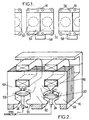
- the device partially shown in Figure 1 comprises a common housing 16 of non-magnetic material, for example light alloy, retaining the ferro-magnetic circuits 54 of two adjacent actuators assigned to the same cylinder on the cylinder head of the engine.
- the housing is pierced with holes 56 of fixing screw passage.
- the ferro-magnetic circuits will generally be disjointed to allow the individual control of the two valves.
- the four coils of the same pair can be powered by a single connector 58 whose general constitution can be either conventional or advantageously that described in the French patent application of the same day as the present application, entitled “Connector power and actuator supply device comprising such connectors "of the applicant, however doubled.
- These connectors can be provided to also transfer the output signals of position sensors. This arrangement requires less space than individual mounting of the actuators and halves the number of connectors.
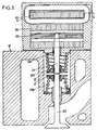
- the magnetic circuits of two adjacent actuators can be fused and have the constitution shown in Figure 2, each complete actuator having for example the elements shown in Figure 3.
- the vertical symmetry planes of the two coils are farther apart than the vertical symmetry planes of the two palettes so that the flows generated by each coil interfere with each other as little as possible.
- the actuator then has a pallet 22 of prismatic shape, made of ferro-magnetic material, fixed on a rod 24 for driving the valve 50.
- Two return springs 28a and 28b are provided to maintain the valve at rest in a substantially median position between the closed position and the fully open position.
- One of the springs 28a is compressed between a plate 30 fixed to the rod 24 and an extension of the housing 16.
- the other spring 28b is compressed between a plate 31 fixed to the valve stem and the bottom of the valve well formed in the cylinder head 12.
- the fixed ferro-magnetic circuit common to the two actuators has a cross section passing through the axis of the two E-shaped pallets with a middle branch 60 and two outer branches 62.
- the lateral branches have a smaller width than the branch median which benefits from the fusion of the two magnetic circuits.
- the outer branches can be relatively wide because of the spacing between two cylinders.
- each pallet 22 has beveled edges parallel to the poles of the associated magnetic circuit.
- the pallet has a central bar-shaped boss which creates or increases an asymmetry of the magnetic circuit and ensures that the initial direction of movement of the pallet from its rest position will be upward.
- the presence of the boss reduces the initial reluctance of the circuit because it reduces the air gap at rest, as shown by the arrows schematically magnetic flux lines.
- the currents flowing through the two coils carried by the same ferromagnetic circuit are in opposite directions.
- the current flowing through each coil can be controlled by a computer (not shown) receiving a signal indicating the position of the pallet of a sensor 24. It can be in particular a Hall effect sensor 64 sensitive to a magnetic pad carried by the rod 24.
- the path of the lines of force of the magnetic flux is such that they do not disturb the measurement by a sensor placed in the oplan of FIG.
Landscapes
- Engineering & Computer Science (AREA)
- Mechanical Engineering (AREA)
- General Engineering & Computer Science (AREA)
- Valve Device For Special Equipments (AREA)
- Magnetically Actuated Valves (AREA)
- Fluid-Driven Valves (AREA)
- Electromagnets (AREA)
Claims (10)
- Steuervorrichtung zur linearen Verstellung von Ventilen eines Motors, umfassend Aktuatoren, deren Anzahl gleich der der Ventile ist und die unabhängig voneinander gesteuert werden, wobei jeder Aktuator einen Anker (22) aus ferromagnetischem Material hat, der an einer Ventilstößelstange befestigt ist, die in einem Gehäuse des Aktuators durch elektromagnetische Mittel verschoben werden kann, die mindestens eine Spule enthalten, die an einem ferromagnetischen Kreis angebracht ist, und mindestens eine Rückstellfeder enthalten, deren eines Ende an der Stange anliegt, dadurch gekennzeichnet, dass die ferromagnetischen Kreise von zwei Aktuatoren, die für zwei gleichartige Ventile ein und desselben Zylinders bestimmt sind, zusammengeschlossen sind.
- Vorrichtung nach Anspruch 1, dadurch gekennzeichnet, dass jeder Aktuator eine einzige Spule (42) hat.
- Vorrichtung nach Anspruch 2, dadurch gekennzeichnet, dass der zwei Aktuatoren gemeinsame, ortsfeste ferromagnetische Kreis in einer durch die Achse der beiden Anker verlaufenden Ebene einen Querschnitt in Form eines E mit einem mittleren Schenkel (60) und zwei äußeren Schenkeln (62) hat.
- Vorrichtung nach Anspruch 2 oder 3, dadurch gekennzeichnet, dass die Ränder jedes Ankers (22) parallel zu den Polen des dazugehörigen magnetischen Kreises abgeschrägt sind.
- Vorrichtung nach Anspruch 2 oder 3, dadurch gekennzeichnet, dass jeder Anker (22) einen zentralen Vorsprung in Form einer Leiste aufweist, die eine Asymmetrie des magnetischen Kreises erzeugt oder vergrößert, um eine anfängliche Bewegungsrichtung des Ankers aus seiner Ruhestellung heraus vorzugeben.
- Vorrichtung nach einem der Ansprüche 2 bis 5, dadurch gekennzeichnet, dass die vertikalen Symmetrieebenen von zwei Spulen benachbarter Aktuatoren weiter voneinander entfernt sind als die vertikalen Symmetrieebenen der beiden Anker.
- Vorrichtung nach Anspruch 2 oder 3, dadurch gekennzeichnet, dass die Ströme, die die beiden von ein und demselben ferromagnetischen Kreis getragenen Spulen durchlaufen, entgegengesetzter Richtung sind.
- Vorrichtung nach einem der vorhergehenden Ansprüche, dadurch gekennzeichnet, dass die ferromagnetischen Kreise eines Paares von zwei Aktuatoren, die für zwei gleichartige Ventile ein und desselben Zylinders bestimmt sind, in ein und demselben Gehäuse enthalten sind.
- Vorrichtung nach Anspruch 8, dadurch gekennzeichnet, dass die Spulen der beiden Aktuatoren über ein und dasselbe Verbindungselement (58) gespeist werden.
- Vorrichtung nach Anspruch 9, dadurch gekennzeichnet, dass das Verbindungselement ebenso zur Übertragung von aus einem Lagesensor des Ankers (64) stammenden Messsignalen verwendet wird.
Applications Claiming Priority (3)
| Application Number | Priority Date | Filing Date | Title |
|---|---|---|---|
| FR9904472A FR2792031B1 (fr) | 1999-04-09 | 1999-04-09 | Dispositif de commande electromagnetique de soupapes |
| FR9904472 | 1999-04-09 | ||
| PCT/FR2000/000896 WO2000061922A1 (fr) | 1999-04-09 | 2000-04-07 | Dispositif de commande electromagnetique de soupapes |
Publications (2)
| Publication Number | Publication Date |
|---|---|
| EP1169552A1 EP1169552A1 (de) | 2002-01-09 |
| EP1169552B1 true EP1169552B1 (de) | 2006-11-02 |
Family
ID=9544233
Family Applications (1)
| Application Number | Title | Priority Date | Filing Date |
|---|---|---|---|
| EP00917161A Expired - Lifetime EP1169552B1 (de) | 1999-04-09 | 2000-04-07 | Elktromagnetische ventilsteuerungseinrichtung |
Country Status (9)
| Country | Link |
|---|---|
| US (1) | US6768406B1 (de) |
| EP (1) | EP1169552B1 (de) |
| JP (1) | JP2002541674A (de) |
| KR (1) | KR100714387B1 (de) |
| AT (1) | ATE344380T1 (de) |
| DE (1) | DE60031660T2 (de) |
| ES (1) | ES2273677T3 (de) |
| FR (1) | FR2792031B1 (de) |
| WO (1) | WO2000061922A1 (de) |
Families Citing this family (29)
| Publication number | Priority date | Publication date | Assignee | Title |
|---|---|---|---|---|
| FR2827007B1 (fr) * | 2001-07-06 | 2003-10-31 | Peugeot Citroen Automobiles Sa | Dispositif de commande a electroaimant, notamment pour une soupape de moteur a combustion interne |
| FR2870563B1 (fr) * | 2004-05-19 | 2006-06-30 | Peugeot Citroen Automobiles Sa | Dispositif d'actionnement de soupapes |
| WO2007134287A1 (en) * | 2006-05-12 | 2007-11-22 | Parker-Hannifin Corporation | Displacement measurement device |
| US20080266038A1 (en) * | 2007-04-24 | 2008-10-30 | Eaton Corporation | Solenoid assembly |
| DE102007052253B4 (de) * | 2007-11-02 | 2023-07-06 | Mercedes-Benz Group AG | Ventiltriebvorrichtung |
| DE102008036462B4 (de) | 2008-08-05 | 2023-12-14 | Mercedes-Benz Group AG | Ventiltriebvorrichtung |
| DE202008015980U1 (de) * | 2008-12-03 | 2010-04-29 | Eto Magnetic Gmbh | Elektromagnetische Aktuatorvorrichtung |
| US9846440B2 (en) | 2011-12-15 | 2017-12-19 | Honeywell International Inc. | Valve controller configured to estimate fuel comsumption |
| US8839815B2 (en) | 2011-12-15 | 2014-09-23 | Honeywell International Inc. | Gas valve with electronic cycle counter |
| US9074770B2 (en) | 2011-12-15 | 2015-07-07 | Honeywell International Inc. | Gas valve with electronic valve proving system |
| US8899264B2 (en) | 2011-12-15 | 2014-12-02 | Honeywell International Inc. | Gas valve with electronic proof of closure system |
| US9851103B2 (en) | 2011-12-15 | 2017-12-26 | Honeywell International Inc. | Gas valve with overpressure diagnostics |
| US9995486B2 (en) | 2011-12-15 | 2018-06-12 | Honeywell International Inc. | Gas valve with high/low gas pressure detection |
| US9557059B2 (en) | 2011-12-15 | 2017-01-31 | Honeywell International Inc | Gas valve with communication link |
| US9835265B2 (en) | 2011-12-15 | 2017-12-05 | Honeywell International Inc. | Valve with actuator diagnostics |
| US8905063B2 (en) | 2011-12-15 | 2014-12-09 | Honeywell International Inc. | Gas valve with fuel rate monitor |
| US8947242B2 (en) | 2011-12-15 | 2015-02-03 | Honeywell International Inc. | Gas valve with valve leakage test |
| US10422531B2 (en) | 2012-09-15 | 2019-09-24 | Honeywell International Inc. | System and approach for controlling a combustion chamber |
| US9234661B2 (en) | 2012-09-15 | 2016-01-12 | Honeywell International Inc. | Burner control system |
| EP2868970B1 (de) | 2013-10-29 | 2020-04-22 | Honeywell Technologies Sarl | Regelungsvorrichtung |
| US10024439B2 (en) | 2013-12-16 | 2018-07-17 | Honeywell International Inc. | Valve over-travel mechanism |
| US9841122B2 (en) | 2014-09-09 | 2017-12-12 | Honeywell International Inc. | Gas valve with electronic valve proving system |
| US9645584B2 (en) | 2014-09-17 | 2017-05-09 | Honeywell International Inc. | Gas valve with electronic health monitoring |
| US10503181B2 (en) | 2016-01-13 | 2019-12-10 | Honeywell International Inc. | Pressure regulator |
| US10564062B2 (en) | 2016-10-19 | 2020-02-18 | Honeywell International Inc. | Human-machine interface for gas valve |
| DE102017121949A1 (de) * | 2017-09-21 | 2019-03-21 | Kendrion (Villingen) Gmbh | Stellvorrichtung, sowie Kraftfahrzeug mit einer Stellvorrichtung |
| US11073281B2 (en) | 2017-12-29 | 2021-07-27 | Honeywell International Inc. | Closed-loop programming and control of a combustion appliance |
| US10697815B2 (en) | 2018-06-09 | 2020-06-30 | Honeywell International Inc. | System and methods for mitigating condensation in a sensor module |
| CN117307286A (zh) * | 2023-11-02 | 2023-12-29 | 广州汽车集团股份有限公司 | 配气系统及车辆 |
Family Cites Families (5)
| Publication number | Priority date | Publication date | Assignee | Title |
|---|---|---|---|---|
| US4779582A (en) * | 1987-08-12 | 1988-10-25 | General Motors Corporation | Bistable electromechanical valve actuator |
| US5548263A (en) * | 1992-10-05 | 1996-08-20 | Aura Systems, Inc. | Electromagnetically actuated valve |
| DE19506566A1 (de) * | 1995-02-24 | 1996-08-29 | Bayerische Motoren Werke Ag | Elektromagnetische Hubventil-Betätigungsvorrichtung |
| DE19518056B4 (de) * | 1995-05-17 | 2005-04-07 | Fev Motorentechnik Gmbh | Einrichtung zur Steuerung der Ankerbewegung einer elektromagnetischen Schaltanordnung und Verfahren zur Ansteuerung |
| DE19719299C1 (de) * | 1997-05-07 | 1998-08-20 | Daimler Benz Ag | Betätigungseinrichtung für Gaswechselventile einer Brennkraftmaschine mit elektromagnetischen Aktuatoren |
-
1999
- 1999-04-09 FR FR9904472A patent/FR2792031B1/fr not_active Expired - Fee Related
-
2000
- 2000-04-07 AT AT00917161T patent/ATE344380T1/de not_active IP Right Cessation
- 2000-04-07 ES ES00917161T patent/ES2273677T3/es not_active Expired - Lifetime
- 2000-04-07 DE DE60031660T patent/DE60031660T2/de not_active Expired - Lifetime
- 2000-04-07 JP JP2000610953A patent/JP2002541674A/ja active Pending
- 2000-04-07 WO PCT/FR2000/000896 patent/WO2000061922A1/fr not_active Ceased
- 2000-04-07 KR KR1020017012837A patent/KR100714387B1/ko not_active Expired - Fee Related
- 2000-04-07 US US09/958,137 patent/US6768406B1/en not_active Expired - Lifetime
- 2000-04-07 EP EP00917161A patent/EP1169552B1/de not_active Expired - Lifetime
Also Published As
| Publication number | Publication date |
|---|---|
| KR20010110727A (ko) | 2001-12-13 |
| KR100714387B1 (ko) | 2007-05-07 |
| ATE344380T1 (de) | 2006-11-15 |
| WO2000061922A1 (fr) | 2000-10-19 |
| US6768406B1 (en) | 2004-07-27 |
| DE60031660D1 (de) | 2006-12-14 |
| ES2273677T3 (es) | 2007-05-16 |
| JP2002541674A (ja) | 2002-12-03 |
| EP1169552A1 (de) | 2002-01-09 |
| DE60031660T2 (de) | 2007-08-30 |
| FR2792031B1 (fr) | 2001-06-08 |
| FR2792031A1 (fr) | 2000-10-13 |
Similar Documents
| Publication | Publication Date | Title |
|---|---|---|
| EP1169552B1 (de) | Elktromagnetische ventilsteuerungseinrichtung | |
| EP1173659B1 (de) | Linearer elektromagnetischer aktor mit einem positionsgeber | |
| EP0974185B1 (de) | Verbesserter linearantrieb | |
| EP0992658B1 (de) | Elektromagnetischer Ventil-Aktuator | |
| EP2792057B1 (de) | Elektromagnetische antriebsvorrichtung | |
| EP1352402B1 (de) | Elektromagnetischer antrieb | |
| FR2784497A1 (fr) | Actionneur electromagnetique a palette aimantee | |
| EP1421590B1 (de) | Elektromagnetisches betätigungsglied mit zwei stabilen endanschlagpositionen, insbesondere zur steuerung von lufteinlasskanalventilen für verbrennungsmotoren | |
| FR2865238A1 (fr) | Actionneur electromecanique de commande de soupape pour moteur a combustion interne et moteur a combustion interne muni d'un tel actionneur | |
| FR2860912A1 (fr) | Actionneur de soupape electromecanique | |
| FR2809487A1 (fr) | Capteur de position axiale pour une tige mobile axialement et actionneur electromagnetique de soupape qui en est equipe | |
| FR2836755A1 (fr) | Actionneur electromagnetique a force d'attraction controlee | |
| FR2784222A1 (fr) | Actionneur electromagnetique de soupape | |
| WO2006000674A1 (fr) | Actionneur electromagnetique comportant un electroaimant a bobine solidaire d'un aimant permanent, et procede d'assemblage d'un tel actionneur | |
| FR2810153A1 (fr) | Actionneur electromagnetique notamment de soupape de moteur a combustion interne | |
| FR2792451A1 (fr) | Dispositif d'actionnement electromagnetique | |
| EP1091368A1 (de) | Elektrische Betätigungsvorrichtung, insbesondere für ein Fahrzeugmotorventil | |
| EP1703089B1 (de) | Elektromagnetisch arbeitende Ventilstelleinrichtung in einem Brennkraftmaschine und Brennkraftmaschine mit einer solchen Ventilstelleinrichtung | |
| FR3076119A1 (fr) | Actionneur a entrainement direct commande en boucle ouverte | |
| FR2904467A1 (fr) | Actionneur electromagnetique a bride de maintien du noyau | |
| CH240533A (fr) | Dispositif commutateur électromagnétique. | |
| FR3026778A1 (fr) | Actionneur electromagnetique a trois bobines | |
| FR2806207A1 (fr) | Electroaimant d'actionnement d'un organe mecanique notamment une soupape de moteur thermique de vehicule automobile | |
| FR2969810A1 (fr) | Actionneur compacts utilisables par exemple pour un vehicule automobile. |
Legal Events
| Date | Code | Title | Description |
|---|---|---|---|
| PUAI | Public reference made under article 153(3) epc to a published international application that has entered the european phase |
Free format text: ORIGINAL CODE: 0009012 |
|
| 17P | Request for examination filed |
Effective date: 20011009 |
|
| AK | Designated contracting states |
Kind code of ref document: A1 Designated state(s): AT BE CH CY DE DK ES FI FR GB GR IE IT LI LU MC NL PT SE |
|
| RAP1 | Party data changed (applicant data changed or rights of an application transferred) |
Owner name: JOHNSON CONTROLS AUTOMOTIVE ELECTRONICS |
|
| RAP1 | Party data changed (applicant data changed or rights of an application transferred) |
Owner name: VALEO SYSTEMES DE CONTROLE MOTEUR |
|
| GRAP | Despatch of communication of intention to grant a patent |
Free format text: ORIGINAL CODE: EPIDOSNIGR1 |
|
| GRAS | Grant fee paid |
Free format text: ORIGINAL CODE: EPIDOSNIGR3 |
|
| GRAA | (expected) grant |
Free format text: ORIGINAL CODE: 0009210 |
|
| AK | Designated contracting states |
Kind code of ref document: B1 Designated state(s): AT BE CH CY DE DK ES FI FR GB GR IE IT LI LU MC NL PT SE |
|
| PG25 | Lapsed in a contracting state [announced via postgrant information from national office to epo] |
Ref country code: AT Free format text: LAPSE BECAUSE OF FAILURE TO SUBMIT A TRANSLATION OF THE DESCRIPTION OR TO PAY THE FEE WITHIN THE PRESCRIBED TIME-LIMIT Effective date: 20061102 Ref country code: IE Free format text: LAPSE BECAUSE OF FAILURE TO SUBMIT A TRANSLATION OF THE DESCRIPTION OR TO PAY THE FEE WITHIN THE PRESCRIBED TIME-LIMIT Effective date: 20061102 Ref country code: FI Free format text: LAPSE BECAUSE OF FAILURE TO SUBMIT A TRANSLATION OF THE DESCRIPTION OR TO PAY THE FEE WITHIN THE PRESCRIBED TIME-LIMIT Effective date: 20061102 Ref country code: NL Free format text: LAPSE BECAUSE OF FAILURE TO SUBMIT A TRANSLATION OF THE DESCRIPTION OR TO PAY THE FEE WITHIN THE PRESCRIBED TIME-LIMIT Effective date: 20061102 |
|
| REG | Reference to a national code |
Ref country code: GB Ref legal event code: FG4D Free format text: NOT ENGLISH |
|
| REG | Reference to a national code |
Ref country code: IE Ref legal event code: FG4D Free format text: LANGUAGE OF EP DOCUMENT: FRENCH |
|
| REG | Reference to a national code |
Ref country code: CH Ref legal event code: EP |
|
| REF | Corresponds to: |
Ref document number: 60031660 Country of ref document: DE Date of ref document: 20061214 Kind code of ref document: P |
|
| PG25 | Lapsed in a contracting state [announced via postgrant information from national office to epo] |
Ref country code: DK Free format text: LAPSE BECAUSE OF FAILURE TO SUBMIT A TRANSLATION OF THE DESCRIPTION OR TO PAY THE FEE WITHIN THE PRESCRIBED TIME-LIMIT Effective date: 20070202 Ref country code: SE Free format text: LAPSE BECAUSE OF FAILURE TO SUBMIT A TRANSLATION OF THE DESCRIPTION OR TO PAY THE FEE WITHIN THE PRESCRIBED TIME-LIMIT Effective date: 20070202 |
|
| PG25 | Lapsed in a contracting state [announced via postgrant information from national office to epo] |
Ref country code: PT Free format text: LAPSE BECAUSE OF FAILURE TO SUBMIT A TRANSLATION OF THE DESCRIPTION OR TO PAY THE FEE WITHIN THE PRESCRIBED TIME-LIMIT Effective date: 20070402 |
|
| NLV1 | Nl: lapsed or annulled due to failure to fulfill the requirements of art. 29p and 29m of the patents act | ||
| REG | Reference to a national code |
Ref country code: ES Ref legal event code: FG2A Ref document number: 2273677 Country of ref document: ES Kind code of ref document: T3 |
|
| GBV | Gb: ep patent (uk) treated as always having been void in accordance with gb section 77(7)/1977 [no translation filed] |
Effective date: 20061102 |
|
| REG | Reference to a national code |
Ref country code: IE Ref legal event code: FD4D |
|
| PLBE | No opposition filed within time limit |
Free format text: ORIGINAL CODE: 0009261 |
|
| STAA | Information on the status of an ep patent application or granted ep patent |
Free format text: STATUS: NO OPPOSITION FILED WITHIN TIME LIMIT |
|
| 26N | No opposition filed |
Effective date: 20070803 |
|
| PG25 | Lapsed in a contracting state [announced via postgrant information from national office to epo] |
Ref country code: GB Free format text: LAPSE BECAUSE OF FAILURE TO SUBMIT A TRANSLATION OF THE DESCRIPTION OR TO PAY THE FEE WITHIN THE PRESCRIBED TIME-LIMIT Effective date: 20061102 |
|
| REG | Reference to a national code |
Ref country code: CH Ref legal event code: PL |
|
| BERE | Be: lapsed |
Owner name: VALEO SYSTEMES DE CONTROLE MOTEUR Effective date: 20070430 |
|
| PG25 | Lapsed in a contracting state [announced via postgrant information from national office to epo] |
Ref country code: CH Free format text: LAPSE BECAUSE OF NON-PAYMENT OF DUE FEES Effective date: 20070430 Ref country code: LI Free format text: LAPSE BECAUSE OF NON-PAYMENT OF DUE FEES Effective date: 20070430 |
|
| PG25 | Lapsed in a contracting state [announced via postgrant information from national office to epo] |
Ref country code: BE Free format text: LAPSE BECAUSE OF NON-PAYMENT OF DUE FEES Effective date: 20070430 |
|
| PG25 | Lapsed in a contracting state [announced via postgrant information from national office to epo] |
Ref country code: GR Free format text: LAPSE BECAUSE OF FAILURE TO SUBMIT A TRANSLATION OF THE DESCRIPTION OR TO PAY THE FEE WITHIN THE PRESCRIBED TIME-LIMIT Effective date: 20070203 |
|
| PG25 | Lapsed in a contracting state [announced via postgrant information from national office to epo] |
Ref country code: MC Free format text: LAPSE BECAUSE OF NON-PAYMENT OF DUE FEES Effective date: 20070430 |
|
| PG25 | Lapsed in a contracting state [announced via postgrant information from national office to epo] |
Ref country code: CY Free format text: LAPSE BECAUSE OF FAILURE TO SUBMIT A TRANSLATION OF THE DESCRIPTION OR TO PAY THE FEE WITHIN THE PRESCRIBED TIME-LIMIT Effective date: 20061102 Ref country code: LU Free format text: LAPSE BECAUSE OF NON-PAYMENT OF DUE FEES Effective date: 20070407 |
|
| REG | Reference to a national code |
Ref country code: DE Ref legal event code: R082 Ref document number: 60031660 Country of ref document: DE Representative=s name: SCHAUMBURG & PARTNER PATENTANWAELTE GBR, DE Ref country code: DE Ref legal event code: R082 Ref document number: 60031660 Country of ref document: DE Representative=s name: SCHAUMBURG UND PARTNER PATENTANWAELTE MBB, DE |
|
| REG | Reference to a national code |
Ref country code: FR Ref legal event code: PLFP Year of fee payment: 17 |
|
| PGFP | Annual fee paid to national office [announced via postgrant information from national office to epo] |
Ref country code: ES Payment date: 20160504 Year of fee payment: 17 Ref country code: DE Payment date: 20160413 Year of fee payment: 17 |
|
| PGFP | Annual fee paid to national office [announced via postgrant information from national office to epo] |
Ref country code: IT Payment date: 20160408 Year of fee payment: 17 Ref country code: FR Payment date: 20160428 Year of fee payment: 17 |
|
| REG | Reference to a national code |
Ref country code: DE Ref legal event code: R119 Ref document number: 60031660 Country of ref document: DE |
|
| REG | Reference to a national code |
Ref country code: FR Ref legal event code: ST Effective date: 20171229 |
|
| PG25 | Lapsed in a contracting state [announced via postgrant information from national office to epo] |
Ref country code: DE Free format text: LAPSE BECAUSE OF NON-PAYMENT OF DUE FEES Effective date: 20171103 Ref country code: FR Free format text: LAPSE BECAUSE OF NON-PAYMENT OF DUE FEES Effective date: 20170502 |
|
| PG25 | Lapsed in a contracting state [announced via postgrant information from national office to epo] |
Ref country code: IT Free format text: LAPSE BECAUSE OF NON-PAYMENT OF DUE FEES Effective date: 20170407 |
|
| REG | Reference to a national code |
Ref country code: ES Ref legal event code: FD2A Effective date: 20180629 |
|
| PG25 | Lapsed in a contracting state [announced via postgrant information from national office to epo] |
Ref country code: ES Free format text: LAPSE BECAUSE OF NON-PAYMENT OF DUE FEES Effective date: 20170408 |