EP1169552B1 - Electromagnetic device for valve control - Google Patents
Electromagnetic device for valve control Download PDFInfo
- Publication number
- EP1169552B1 EP1169552B1 EP00917161A EP00917161A EP1169552B1 EP 1169552 B1 EP1169552 B1 EP 1169552B1 EP 00917161 A EP00917161 A EP 00917161A EP 00917161 A EP00917161 A EP 00917161A EP 1169552 B1 EP1169552 B1 EP 1169552B1
- Authority
- EP
- European Patent Office
- Prior art keywords
- actuators
- valves
- ferromagnetic
- armature
- actuator
- Prior art date
- Legal status (The legal status is an assumption and is not a legal conclusion. Google has not performed a legal analysis and makes no representation as to the accuracy of the status listed.)
- Expired - Lifetime
Links
Images
Classifications
-
- F—MECHANICAL ENGINEERING; LIGHTING; HEATING; WEAPONS; BLASTING
- F01—MACHINES OR ENGINES IN GENERAL; ENGINE PLANTS IN GENERAL; STEAM ENGINES
- F01L—CYCLICALLY OPERATING VALVES FOR MACHINES OR ENGINES
- F01L9/00—Valve-gear or valve arrangements actuated non-mechanically
- F01L9/20—Valve-gear or valve arrangements actuated non-mechanically by electric means
Definitions
- the invention relates to axially linear displacement control devices comprising actuators in number equal to that of the valves, each actuator having a pallet of ferro-magnetic material attached to a valve push rod movable in a housing of the actuator by electromagnetic means having at least one coil mounted on a ferromagnetic circuit and having at least one return spring, one end of which bears against the rod.
- Devices of this kind may have two opposing return springs (US Patent 4,614,170 or FR 98 12489 patent application) or a single spring alternately working in traction and compression (patent application FR 98 11670).
- the electromagnetic means of an actuator may comprise two coils whose excitation tends to move the pallet in opposite directions (DE 197 19 299). They can also - and this solution will generally be preferable for reasons of cost, reduction of space and reduction of the number of electrical connections - use a single coil whose ferro-magnetic circuit has a constitution such that it offers, in combination with the pallet, two stable paths of magnetic flux corresponding to the opening and closing states of the valve, respectively (FR 98 application 12489 and corresponding EP application).
- Such a device comprises as many actuators as valves.
- eight actuators must be placed side by side.
- the power of an actuator is limited, given thickness, and this thickness itself is limited because the The distribution of the actuators must be the same as that of the valves.
- the power that can be achieved with individual actuators may be insufficient, at least for the exhaust valves that are the most demanding at high engine load because of the back pressure in the engine. the combustion chamber.
- the need for an electrical power connector per actuator is expensive and reduces reliability.
- the invention aims in particular to provide a valve control device for two-valve engine of the same type per cylinder of reduced size and increased reliability.
- the invention proposes for this purpose a device in which the ferro-magnetic circuits of two actuators assigned to two valves of the same type of the same cylinder are contained in a common housing and the coils of the two actuators can consequently be supplied by the intermediate of the same power connector.
- This single connector can moreover be used to transmit measurement signals from a position sensor of the pallet to the outside.
- the invention proposes a device in which the ferro-magnetic circuits of two actuators assigned to two valves of the same type of the same cylinder are merged. Not only does this arrangement reduce the space requirement and therefore makes it possible to locally increase the section of iron by taking advantage of the free space between two cylinders, but it also makes it possible to increase the section of the common part which benefits entirely to the control of only one of the valves when the other remains at rest, for example at the start of the oscillation of the valves.
- the invention is particularly easy to implement in the case of single-coil actuators for which one can also place sensors of the axial position of the rod and the pallet, detecting the position of a magnet fixed to the rod, in an area where the magnetic flux created by the coil is still very small and does not disrupt the operation through the symmetry of the planar lines of force.
- Valve actuators are electromagnetic control and can be a single coil, as will be described later, or two coils, such as that described in the patent application FR 98 11670 already mentioned.
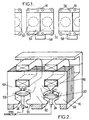
- the device partially shown in Figure 1 comprises a common housing 16 of non-magnetic material, for example light alloy, retaining the ferro-magnetic circuits 54 of two adjacent actuators assigned to the same cylinder on the cylinder head of the engine.
- the housing is pierced with holes 56 of fixing screw passage.
- the ferro-magnetic circuits will generally be disjointed to allow the individual control of the two valves.
- the four coils of the same pair can be powered by a single connector 58 whose general constitution can be either conventional or advantageously that described in the French patent application of the same day as the present application, entitled “Connector power and actuator supply device comprising such connectors "of the applicant, however doubled.
- These connectors can be provided to also transfer the output signals of position sensors. This arrangement requires less space than individual mounting of the actuators and halves the number of connectors.
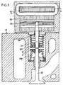
- the magnetic circuits of two adjacent actuators can be fused and have the constitution shown in Figure 2, each complete actuator having for example the elements shown in Figure 3.
- the vertical symmetry planes of the two coils are farther apart than the vertical symmetry planes of the two palettes so that the flows generated by each coil interfere with each other as little as possible.
- the actuator then has a pallet 22 of prismatic shape, made of ferro-magnetic material, fixed on a rod 24 for driving the valve 50.
- Two return springs 28a and 28b are provided to maintain the valve at rest in a substantially median position between the closed position and the fully open position.
- One of the springs 28a is compressed between a plate 30 fixed to the rod 24 and an extension of the housing 16.
- the other spring 28b is compressed between a plate 31 fixed to the valve stem and the bottom of the valve well formed in the cylinder head 12.
- the fixed ferro-magnetic circuit common to the two actuators has a cross section passing through the axis of the two E-shaped pallets with a middle branch 60 and two outer branches 62.
- the lateral branches have a smaller width than the branch median which benefits from the fusion of the two magnetic circuits.
- the outer branches can be relatively wide because of the spacing between two cylinders.
- each pallet 22 has beveled edges parallel to the poles of the associated magnetic circuit.
- the pallet has a central bar-shaped boss which creates or increases an asymmetry of the magnetic circuit and ensures that the initial direction of movement of the pallet from its rest position will be upward.
- the presence of the boss reduces the initial reluctance of the circuit because it reduces the air gap at rest, as shown by the arrows schematically magnetic flux lines.
- the currents flowing through the two coils carried by the same ferromagnetic circuit are in opposite directions.
- the current flowing through each coil can be controlled by a computer (not shown) receiving a signal indicating the position of the pallet of a sensor 24. It can be in particular a Hall effect sensor 64 sensitive to a magnetic pad carried by the rod 24.
- the path of the lines of force of the magnetic flux is such that they do not disturb the measurement by a sensor placed in the oplan of FIG.
Landscapes
- Engineering & Computer Science (AREA)
- Mechanical Engineering (AREA)
- General Engineering & Computer Science (AREA)
- Valve Device For Special Equipments (AREA)
- Magnetically Actuated Valves (AREA)
- Fluid-Driven Valves (AREA)
- Electromagnets (AREA)
Abstract
Description
L'invention concerne les dispositifs de commande de soupapes à déplacement linéaire suivant un axe, comprenant des actionneurs en nombre égal à celui des soupapes, chaque actionneur ayant une palette en matériau ferro-magnétique fixée à une tige de poussée de soupape déplaçable dans un boîtier de l'actionneur par des moyens électro-magnétiques ayant au moins une bobine montée sur un circuit ferro-magnétique et ayant au moins un ressort de rappel dont une extrémité est en appui contre la tige.The invention relates to axially linear displacement control devices comprising actuators in number equal to that of the valves, each actuator having a pallet of ferro-magnetic material attached to a valve push rod movable in a housing of the actuator by electromagnetic means having at least one coil mounted on a ferromagnetic circuit and having at least one return spring, one end of which bears against the rod.
Les dispositifs de ce genre peuvent avoir deux ressorts de rappel antagonistes (brevet US 4 614 170 ou demande de brevet FR 98 12489) ou un seul ressort travaillant alternativement en traction et en compression (demande de brevet FR 98 11670). Les moyens électromagnétiques d'un actionneur peuvent comporter deux bobines dont l'excitation tend à déplacer la palette dans des directions opposées (DE 197 19 299). Ils peuvent également -et cette solution sera généralement préférable pour des raisons de coût, de réduction d'encombrement et de réduction du nombre des liaisons électriques- utiliser une bobine unique dont le circuit ferro-magnétique a une constitution telle qu'il offre, en combinaison avec la palette, deux cheminements stables de flux magnétique correspondant à des états d'ouverture et de fermeture de la soupape, respectivement (demande FR 98 12489 et demande EP correspondante).Devices of this kind may have two opposing return springs (US Patent 4,614,170 or FR 98 12489 patent application) or a single spring alternately working in traction and compression (patent application FR 98 11670). The electromagnetic means of an actuator may comprise two coils whose excitation tends to move the pallet in opposite directions (DE 197 19 299). They can also - and this solution will generally be preferable for reasons of cost, reduction of space and reduction of the number of electrical connections - use a single coil whose ferro-magnetic circuit has a constitution such that it offers, in combination with the pallet, two stable paths of magnetic flux corresponding to the opening and closing states of the valve, respectively (FR 98 application 12489 and corresponding EP application).
Un tel dispositif comporte autant d'actionneurs que de soupapes. Sur un moteur à seize soupapes disposées en deux lignes, huit actionneurs doivent être placé côte à côte. La puissance d'un actionneur est limitée, à épaisseur donnée, et cette épaisseur elle-même est limitée du fait que la répartition des actionneurs doit être la même que celle des soupapes. Sur des moteurs de faible cylindrée, la puissance que l'on peut obtenir avec des actionneurs individuels peut se révéler insuffisante, au moins pour les soupapes d'échappement qui sont les plus exigeantes à forte charge du moteur du fait de la contre-pression dans la chambre de combustion. Par ailleurs la nécessité d'un connecteur électrique de puissance par actionneur est coûteuse et réduit la fiabilité.Such a device comprises as many actuators as valves. On a sixteen-valve engine arranged in two lines, eight actuators must be placed side by side. The power of an actuator is limited, given thickness, and this thickness itself is limited because the The distribution of the actuators must be the same as that of the valves. On small displacement engines, the power that can be achieved with individual actuators may be insufficient, at least for the exhaust valves that are the most demanding at high engine load because of the back pressure in the engine. the combustion chamber. In addition, the need for an electrical power connector per actuator is expensive and reduces reliability.
L'invention vise notamment à fournir un dispositif de commande de soupapes pour moteur à deux soupapes du même type par cylindre d'encombrement réduit et de fiabilité accrue.The invention aims in particular to provide a valve control device for two-valve engine of the same type per cylinder of reduced size and increased reliability.
L'invention propose dans ce but un dispositif dans lequel les circuits ferro-magnétiques de deux actionneurs affectés à deux soupapes du même type d'un même cylindre sont contenus dans un boîtier commun et les bobines des deux actionneurs peuvent en conséquence être alimentées par l'intermédiaire d'un même connecteur de puissance. Ce connecteur unique peut au surplus être utilisé pour transmettre des signaux de mesure provenant d'un capteur de position de la palette vers l'extérieur.The invention proposes for this purpose a device in which the ferro-magnetic circuits of two actuators assigned to two valves of the same type of the same cylinder are contained in a common housing and the coils of the two actuators can consequently be supplied by the intermediate of the same power connector. This single connector can moreover be used to transmit measurement signals from a position sensor of the pallet to the outside.
Suivant un autre aspect de l'invention, celle-ci propose un dispositif dans lequel les circuits ferro-magnétiques de deux actionneurs affectés à deux soupapes de même type d'un même cylindre sont fusionnés. Non seulement cette disposition réduit l'encombrement et donc permet d'accroître localement la section de fer en profitant de l'espace libre entre deux cylindres mais encore elle permet d'augmenter la section de la partie commune qui bénéficie tout entière à la commande d'une seule des soupapes lorsque l'autre reste au repos, par exemple au démarrage de l'oscillation des soupapes.According to another aspect of the invention, it proposes a device in which the ferro-magnetic circuits of two actuators assigned to two valves of the same type of the same cylinder are merged. Not only does this arrangement reduce the space requirement and therefore makes it possible to locally increase the section of iron by taking advantage of the free space between two cylinders, but it also makes it possible to increase the section of the common part which benefits entirely to the control of only one of the valves when the other remains at rest, for example at the start of the oscillation of the valves.
L'invention est particulièrement aisée à mettre en oeuvre dans le cas d'actionneurs à une seule bobine pour lesquels on peut de plus placer des capteurs de la position axiale de la tige et de la palette, détectant la position d'un aimant fixé à la tige, dans une zone où le flux magnétique créé par la bobine est toujours très réduit et ne perturbe pas le fonctionnement grâce à la symétrie des planaires des lignes de force.The invention is particularly easy to implement in the case of single-coil actuators for which one can also place sensors of the axial position of the rod and the pallet, detecting the position of a magnet fixed to the rod, in an area where the magnetic flux created by the coil is still very small and does not disrupt the operation through the symmetry of the planar lines of force.
Les caractéristiques ci-dessus ainsi que d'autres apparaîtront mieux à la lecture de la description qui suit d'un mode particulier de réalisation, donné à titre d'exemple non limitatif. La description se réfère aux dessins qui l'accompagnent, dans lesquels :
- la figure 1 est une vue de dessus d'une fraction d'un dispositif de commande comportant des actionneurs regroupés par paires dans un même boîtier ;
- la figure 2 est une vue en coupe d'un couple d'actionneurs conforme à un mode particulier de réalisation, suivant un plan passant par les axes de ces actionneurs ;
- la figure 3 est une vue en coupe d'un actionneur mono-bobine en coupe suivant un plan orthogonal à celui de la figure 2 et passant par l'axe de l' actionneur.
- Figure 1 is a top view of a fraction of a control device comprising actuators grouped in pairs in the same housing;
- Figure 2 is a sectional view of a pair of actuators according to a particular embodiment, along a plane passing through the axes of these actuators;
- Figure 3 is a sectional view of a single-coil actuator in section along a plane orthogonal to that of Figure 2 and passing through the axis of the actuator.
Il sera essentiellement question maintenant d'un dispositif destiné à un moteur comportant deux soupapes d'admission et deux soupapes d'échappement par cylindre. Toutes les soupapes d'un même type, telles que les soupapes 50 sur la figure 1,- sont disposées en ligne et l'écartement de deux soupapes associées à un même cylindre est plus faible que celui de deux soupapes adjacentes associées à deux cylindres différents. Les actionneurs de soupape sont à commande électromagnétique et peuvent être à une seule bobine, comme celui qui sera décrit plus loin, ou à deux bobines, tel que celui décrit dans la demande de brevet FR 98 11670 déjà mentionnée.It will now essentially be a device for an engine having two intake valves and two exhaust valves per cylinder. All the valves of the same type, such as the
Le dispositif montré partiellement sur la figure 1 comporte un boîtier commun 16 en matériau non magnétique, en alliage léger par exemple, retenant les circuits ferro-magnétiques 54 de deux actionneurs adjacents affectés à un même cylindre sur la culasse du moteur. Pour cela le boîtier est percé de trous 56 de passage de vis de fixation. Dans le cas d'actionneurs à deux bobines, les circuits ferro-magnétiques seront généralement disjoints pour permettre la commande individuelle des deux soupapes.The device partially shown in Figure 1 comprises a
Les quatre bobines d'un même couple (deux par actionneur) peuvent être alimentées par un connecteur unique 58 dont la constitution générale peut être soit classique, soit avantageusement celle décrite dans la demande_de brevet français du même jour que la présente demande, intitulée « Connecteur de puissance et dispositif d'alimentation d'actionneurs comportant de tels connecteurs » de la demanderesse, toutefois doublée. Ces connecteurs peuvent être prévus pour transférer également les signaux de sortie de capteurs de position. Cette disposition exige moins de place qu'un montage individuel des actionneurs et réduit de moitié le nombre de connecteurs.The four coils of the same pair (two per actuator) can be powered by a
Lorsque les actionneurs sont à une seule bobine, les circuits magnétiques de deux actionneurs adjacents peuvent être fusionnés et avoir la constitution montrée en figure 2, chaque actionneur complet ayant par exemple les éléments montrés en figure 3. Les plans de symétrie verticaux des deux bobines sont plus éloignés entre eux que les plans de symétrie verticaux des deux palettes pour que les flux générés par chaque bobine se gênent réciproquement le moins possible. L'actionneur présente alors une palette 22 de forme prismatique, en matériau ferro-magnétique, fixée sur une tige 24 d'entraînement de la soupape 50.When the actuators are single coil, the magnetic circuits of two adjacent actuators can be fused and have the constitution shown in Figure 2, each complete actuator having for example the elements shown in Figure 3. The vertical symmetry planes of the two coils are farther apart than the vertical symmetry planes of the two palettes so that the flows generated by each coil interfere with each other as little as possible. The actuator then has a
Deux ressorts de rappel 28a et 28b sont prévus pour maintenir la soupape au repos dans une position sensiblement médiane entre la position de fermeture et la position de pleine ouverture. Un des ressorts 28a est comprimé entre un plateau 30 fixé à la tige 24 et un prolongement du boîtier 16. L'autre ressort 28b est comprimé entre un plateau 31 fixé à la queue de soupape et le fond du puits de soupape ménagé dans la culasse 12.Two
Le circuit ferro-magnétique fixe commun aux deux actionneurs présente une section droite passant par l'axe des deux palettes en forme de E avec une branche médiane 60 et deux branches externes 62. Les branches latérales ont une largeur plus faible que celle de la branche médiane qui profite de la fusion des deux circuits magnétiques. Cependant les branches externes peuvent être relativement larges du fait de l'écartement entre deux cylindres.The fixed ferro-magnetic circuit common to the two actuators has a cross section passing through the axis of the two E-shaped pallets with a
Dans le mode de réalisation montré en figure 2, chaque palette 22 présente des bords biseautés parallèlement aux pôles du circuit magnétique associé. De plus la palette présente un bossage central en forme de barrette qui créée ou augmente une dissymétrie du circuit magnétique et garantit que le sens initial de déplacement de la palette à partir de sa position de repos sera vers le haut. De plus la présence du bossage réduit la réluctance initiale du circuit du fait qu'elle réduit l'entrefer au repos, comme le montrent les flèches schématisant les lignes de flux magnétiques. Lorsque la palette est collée sur le pôle supérieur, comme indiqué à gauche sur la figure, le bossage est court-circuité et n'affaiblit pas la force de collage.In the embodiment shown in FIG. 2, each
Les courants parcourant les deux bobines portées par un même circuit ferro-magnétique sont de sens opposés. Le courant qui parcourt chaque bobine peut être piloté par un calculateur non représenté recevant un signal indiquant la position de la palette d'un capteur 24. Il peut s'agir notamment d'un capteur à effet Hall 64 sensible à un plot magnétique porté par la tige 24. Le trajet des lignes de force du flux magnétique est tel qu'elles ne perturbent pas la mesure par un capteur placé dans le oplan de la figure 3.The currents flowing through the two coils carried by the same ferromagnetic circuit are in opposite directions. The current flowing through each coil can be controlled by a computer (not shown) receiving a signal indicating the position of the pallet of a
Claims (10)
- Apparatus for controlling valves that move linearly along respective axes, the apparatus comprising a number of independently-controlled actuators equal to the number of valves, each actuator having an armature (22) of ferromagnetic material fixed to a valve push rod movable in a housing of the actuator by electromagnetic means having at least one coil mounted on a ferromagnetic circuit and having at least one return spring with an end bearing against the rod, the apparatus is characterized in that the ferromagnetic circuits of the two actuators allocated to two valves of the same type for a single cylinder are merged.
- Apparatus according to claim 1, characterized in that each actuator has a single coil (42).
- Apparatus according to claim 2, characterized in that the fixed ferromagnetic circuit that is common to both actuators has a right section in a plane containing the axes of both armatures, that is E-shaped with a middle branch (60) and two outer branches (62).
- Apparatus according to claim 2 or claim 3, characterized in that each armature (22) has edges chamfered parallel to the poles of the associated magnetic circuit.
- Apparatus according to claim 2 or claim 3, characterized in that each armature (22) has a central bulge in the form of a bar which creates or increases asymmetry of the magnetic circuit to impose an initial direction on the displacement of the armature from its rest position.
- Apparatus according anyone of claims 2 to 5, characterized in that the vertical planes of symmetry of the two coils are further apart from each other than are the vertical planes of symmetry of the two armatures.
- Apparatus according to claim 2 or 3, characterized in that the currents carried by the two coils mounted on a common ferromagnetic circuit are opposite in direction.
- Apparatus according to anyone of the preceding claims, characterized in that the ferromagnetic circuits of a pair of actuators allocated to two valves of the same type for a single cylinder are both contained in a same housing.
- Apparatus according to claim 8, characterized in that the coils of the two actuators are fed via a common connector (58).
- Apparatus according to claim 9, characterized in that the connector is used for transmitting measurement signals coming from a sensor (64) for sensing the position of the armature.
Applications Claiming Priority (3)
| Application Number | Priority Date | Filing Date | Title |
|---|---|---|---|
| FR9904472A FR2792031B1 (en) | 1999-04-09 | 1999-04-09 | ELECTROMAGNETIC VALVE CONTROL DEVICE |
| FR9904472 | 1999-04-09 | ||
| PCT/FR2000/000896 WO2000061922A1 (en) | 1999-04-09 | 2000-04-07 | Electromagnetic device for valve control |
Publications (2)
| Publication Number | Publication Date |
|---|---|
| EP1169552A1 EP1169552A1 (en) | 2002-01-09 |
| EP1169552B1 true EP1169552B1 (en) | 2006-11-02 |
Family
ID=9544233
Family Applications (1)
| Application Number | Title | Priority Date | Filing Date |
|---|---|---|---|
| EP00917161A Expired - Lifetime EP1169552B1 (en) | 1999-04-09 | 2000-04-07 | Electromagnetic device for valve control |
Country Status (9)
| Country | Link |
|---|---|
| US (1) | US6768406B1 (en) |
| EP (1) | EP1169552B1 (en) |
| JP (1) | JP2002541674A (en) |
| KR (1) | KR100714387B1 (en) |
| AT (1) | ATE344380T1 (en) |
| DE (1) | DE60031660T2 (en) |
| ES (1) | ES2273677T3 (en) |
| FR (1) | FR2792031B1 (en) |
| WO (1) | WO2000061922A1 (en) |
Families Citing this family (29)
| Publication number | Priority date | Publication date | Assignee | Title |
|---|---|---|---|---|
| FR2827007B1 (en) * | 2001-07-06 | 2003-10-31 | Peugeot Citroen Automobiles Sa | ELECTROMAGNET CONTROL DEVICE, PARTICULARLY FOR A VALVE OF AN INTERNAL COMBUSTION ENGINE |
| FR2870563B1 (en) * | 2004-05-19 | 2006-06-30 | Peugeot Citroen Automobiles Sa | VALVE ACTUATING DEVICE |
| WO2007134287A1 (en) * | 2006-05-12 | 2007-11-22 | Parker-Hannifin Corporation | Displacement measurement device |
| US20080266038A1 (en) * | 2007-04-24 | 2008-10-30 | Eaton Corporation | Solenoid assembly |
| DE102007052253B4 (en) * | 2007-11-02 | 2023-07-06 | Mercedes-Benz Group AG | valve train device |
| DE102008036462B4 (en) | 2008-08-05 | 2023-12-14 | Mercedes-Benz Group AG | Valve drive device |
| DE202008015980U1 (en) * | 2008-12-03 | 2010-04-29 | Eto Magnetic Gmbh | Electromagnetic actuator device |
| US9846440B2 (en) | 2011-12-15 | 2017-12-19 | Honeywell International Inc. | Valve controller configured to estimate fuel comsumption |
| US8839815B2 (en) | 2011-12-15 | 2014-09-23 | Honeywell International Inc. | Gas valve with electronic cycle counter |
| US9074770B2 (en) | 2011-12-15 | 2015-07-07 | Honeywell International Inc. | Gas valve with electronic valve proving system |
| US8899264B2 (en) | 2011-12-15 | 2014-12-02 | Honeywell International Inc. | Gas valve with electronic proof of closure system |
| US9851103B2 (en) | 2011-12-15 | 2017-12-26 | Honeywell International Inc. | Gas valve with overpressure diagnostics |
| US9995486B2 (en) | 2011-12-15 | 2018-06-12 | Honeywell International Inc. | Gas valve with high/low gas pressure detection |
| US9557059B2 (en) | 2011-12-15 | 2017-01-31 | Honeywell International Inc | Gas valve with communication link |
| US9835265B2 (en) | 2011-12-15 | 2017-12-05 | Honeywell International Inc. | Valve with actuator diagnostics |
| US8905063B2 (en) | 2011-12-15 | 2014-12-09 | Honeywell International Inc. | Gas valve with fuel rate monitor |
| US8947242B2 (en) | 2011-12-15 | 2015-02-03 | Honeywell International Inc. | Gas valve with valve leakage test |
| US10422531B2 (en) | 2012-09-15 | 2019-09-24 | Honeywell International Inc. | System and approach for controlling a combustion chamber |
| US9234661B2 (en) | 2012-09-15 | 2016-01-12 | Honeywell International Inc. | Burner control system |
| EP2868970B1 (en) | 2013-10-29 | 2020-04-22 | Honeywell Technologies Sarl | Regulating device |
| US10024439B2 (en) | 2013-12-16 | 2018-07-17 | Honeywell International Inc. | Valve over-travel mechanism |
| US9841122B2 (en) | 2014-09-09 | 2017-12-12 | Honeywell International Inc. | Gas valve with electronic valve proving system |
| US9645584B2 (en) | 2014-09-17 | 2017-05-09 | Honeywell International Inc. | Gas valve with electronic health monitoring |
| US10503181B2 (en) | 2016-01-13 | 2019-12-10 | Honeywell International Inc. | Pressure regulator |
| US10564062B2 (en) | 2016-10-19 | 2020-02-18 | Honeywell International Inc. | Human-machine interface for gas valve |
| DE102017121949A1 (en) * | 2017-09-21 | 2019-03-21 | Kendrion (Villingen) Gmbh | Actuating device, as well as motor vehicle with an adjusting device |
| US11073281B2 (en) | 2017-12-29 | 2021-07-27 | Honeywell International Inc. | Closed-loop programming and control of a combustion appliance |
| US10697815B2 (en) | 2018-06-09 | 2020-06-30 | Honeywell International Inc. | System and methods for mitigating condensation in a sensor module |
| CN117307286A (en) * | 2023-11-02 | 2023-12-29 | 广州汽车集团股份有限公司 | Gas distribution system and vehicle |
Family Cites Families (5)
| Publication number | Priority date | Publication date | Assignee | Title |
|---|---|---|---|---|
| US4779582A (en) * | 1987-08-12 | 1988-10-25 | General Motors Corporation | Bistable electromechanical valve actuator |
| US5548263A (en) * | 1992-10-05 | 1996-08-20 | Aura Systems, Inc. | Electromagnetically actuated valve |
| DE19506566A1 (en) * | 1995-02-24 | 1996-08-29 | Bayerische Motoren Werke Ag | Electromagnetic piston valve actuation device for internal combustion engine |
| DE19518056B4 (en) * | 1995-05-17 | 2005-04-07 | Fev Motorentechnik Gmbh | Device for controlling the armature movement of an electromagnetic switching device and method for driving |
| DE19719299C1 (en) * | 1997-05-07 | 1998-08-20 | Daimler Benz Ag | Gas exchange valve actuator for internal combustion engine |
-
1999
- 1999-04-09 FR FR9904472A patent/FR2792031B1/en not_active Expired - Fee Related
-
2000
- 2000-04-07 AT AT00917161T patent/ATE344380T1/en not_active IP Right Cessation
- 2000-04-07 ES ES00917161T patent/ES2273677T3/en not_active Expired - Lifetime
- 2000-04-07 DE DE60031660T patent/DE60031660T2/en not_active Expired - Lifetime
- 2000-04-07 JP JP2000610953A patent/JP2002541674A/en active Pending
- 2000-04-07 WO PCT/FR2000/000896 patent/WO2000061922A1/en not_active Ceased
- 2000-04-07 KR KR1020017012837A patent/KR100714387B1/en not_active Expired - Fee Related
- 2000-04-07 US US09/958,137 patent/US6768406B1/en not_active Expired - Lifetime
- 2000-04-07 EP EP00917161A patent/EP1169552B1/en not_active Expired - Lifetime
Also Published As
| Publication number | Publication date |
|---|---|
| KR20010110727A (en) | 2001-12-13 |
| KR100714387B1 (en) | 2007-05-07 |
| ATE344380T1 (en) | 2006-11-15 |
| WO2000061922A1 (en) | 2000-10-19 |
| US6768406B1 (en) | 2004-07-27 |
| DE60031660D1 (en) | 2006-12-14 |
| ES2273677T3 (en) | 2007-05-16 |
| JP2002541674A (en) | 2002-12-03 |
| EP1169552A1 (en) | 2002-01-09 |
| DE60031660T2 (en) | 2007-08-30 |
| FR2792031B1 (en) | 2001-06-08 |
| FR2792031A1 (en) | 2000-10-13 |
Similar Documents
| Publication | Publication Date | Title |
|---|---|---|
| EP1169552B1 (en) | Electromagnetic device for valve control | |
| EP1173659B1 (en) | Electromagnetic linear actuator with position sensor | |
| EP0974185B1 (en) | Improved linear actuator | |
| EP0992658B1 (en) | Electromagnetic valve actuator | |
| EP2792057B1 (en) | Electromagnetic actuator | |
| EP1352402B1 (en) | Electromagnetic actuator | |
| FR2784497A1 (en) | ELECTROMAGNETIC ACTUATOR WITH MAGNETIC PALLET | |
| EP1421590B1 (en) | Electromagnetic actuator with two stable end-of-travel positions, in particular for controlling air intake duct valves for internal combustion engines | |
| FR2865238A1 (en) | ELECTROMECHANICAL VALVE CONTROL ACTUATOR FOR INTERNAL COMBUSTION ENGINE AND INTERNAL COMBUSTION ENGINE EQUIPPED WITH SUCH ACTUATOR | |
| FR2860912A1 (en) | ELECTROMECHANICAL VALVE ACTUATOR | |
| FR2809487A1 (en) | AXIAL POSITION SENSOR FOR AN AXISALLY MOBILE ROD AND ELECTROMAGNETIC VALVE ACTUATOR PROVIDED WITH THE SAME | |
| FR2836755A1 (en) | ELECTROMAGNETIC ACTUATOR WITH CONTROLLED ATTRACTION FORCE | |
| FR2784222A1 (en) | ELECTROMAGNETIC VALVE ACTUATOR | |
| WO2006000674A1 (en) | Electromagnetic actuator comprising an electromagnet provided with a permanent magnet solenoid and method for assembling said actuator | |
| FR2810153A1 (en) | Electromagnetic actuator for IC engine valve includes armature plate of laminated construction to minimize Foucault currents | |
| FR2792451A1 (en) | ELECTROMAGNETIC ACTUATION DEVICE | |
| EP1091368A1 (en) | Electric actuator in particular for a motor vehicle valve | |
| EP1703089B1 (en) | Electromagnetic valve actuator for an internal combustion engine, and engine with such an actuator | |
| FR3076119A1 (en) | ACTUATOR WITH DIRECT DRIVE CONTROL OPEN LOOP | |
| FR2904467A1 (en) | ELECTROMAGNETIC ACTUATOR WITH CORE RETAINING FLANGE | |
| CH240533A (en) | Electromagnetic switching device. | |
| FR3026778A1 (en) | ELECTROMAGNETIC ACTUATOR WITH THREE COILS | |
| FR2806207A1 (en) | Electromagnet for actuating a mechanical part, especially a valve of an automotive vehicle IC engine, has magnetic poles placed to automatically brake the movable element thus reducing noise | |
| FR2969810A1 (en) | COMPACT ACTUATOR FOR USE, FOR EXAMPLE, IN A MOTOR VEHICLE. |
Legal Events
| Date | Code | Title | Description |
|---|---|---|---|
| PUAI | Public reference made under article 153(3) epc to a published international application that has entered the european phase |
Free format text: ORIGINAL CODE: 0009012 |
|
| 17P | Request for examination filed |
Effective date: 20011009 |
|
| AK | Designated contracting states |
Kind code of ref document: A1 Designated state(s): AT BE CH CY DE DK ES FI FR GB GR IE IT LI LU MC NL PT SE |
|
| RAP1 | Party data changed (applicant data changed or rights of an application transferred) |
Owner name: JOHNSON CONTROLS AUTOMOTIVE ELECTRONICS |
|
| RAP1 | Party data changed (applicant data changed or rights of an application transferred) |
Owner name: VALEO SYSTEMES DE CONTROLE MOTEUR |
|
| GRAP | Despatch of communication of intention to grant a patent |
Free format text: ORIGINAL CODE: EPIDOSNIGR1 |
|
| GRAS | Grant fee paid |
Free format text: ORIGINAL CODE: EPIDOSNIGR3 |
|
| GRAA | (expected) grant |
Free format text: ORIGINAL CODE: 0009210 |
|
| AK | Designated contracting states |
Kind code of ref document: B1 Designated state(s): AT BE CH CY DE DK ES FI FR GB GR IE IT LI LU MC NL PT SE |
|
| PG25 | Lapsed in a contracting state [announced via postgrant information from national office to epo] |
Ref country code: AT Free format text: LAPSE BECAUSE OF FAILURE TO SUBMIT A TRANSLATION OF THE DESCRIPTION OR TO PAY THE FEE WITHIN THE PRESCRIBED TIME-LIMIT Effective date: 20061102 Ref country code: IE Free format text: LAPSE BECAUSE OF FAILURE TO SUBMIT A TRANSLATION OF THE DESCRIPTION OR TO PAY THE FEE WITHIN THE PRESCRIBED TIME-LIMIT Effective date: 20061102 Ref country code: FI Free format text: LAPSE BECAUSE OF FAILURE TO SUBMIT A TRANSLATION OF THE DESCRIPTION OR TO PAY THE FEE WITHIN THE PRESCRIBED TIME-LIMIT Effective date: 20061102 Ref country code: NL Free format text: LAPSE BECAUSE OF FAILURE TO SUBMIT A TRANSLATION OF THE DESCRIPTION OR TO PAY THE FEE WITHIN THE PRESCRIBED TIME-LIMIT Effective date: 20061102 |
|
| REG | Reference to a national code |
Ref country code: GB Ref legal event code: FG4D Free format text: NOT ENGLISH |
|
| REG | Reference to a national code |
Ref country code: IE Ref legal event code: FG4D Free format text: LANGUAGE OF EP DOCUMENT: FRENCH |
|
| REG | Reference to a national code |
Ref country code: CH Ref legal event code: EP |
|
| REF | Corresponds to: |
Ref document number: 60031660 Country of ref document: DE Date of ref document: 20061214 Kind code of ref document: P |
|
| PG25 | Lapsed in a contracting state [announced via postgrant information from national office to epo] |
Ref country code: DK Free format text: LAPSE BECAUSE OF FAILURE TO SUBMIT A TRANSLATION OF THE DESCRIPTION OR TO PAY THE FEE WITHIN THE PRESCRIBED TIME-LIMIT Effective date: 20070202 Ref country code: SE Free format text: LAPSE BECAUSE OF FAILURE TO SUBMIT A TRANSLATION OF THE DESCRIPTION OR TO PAY THE FEE WITHIN THE PRESCRIBED TIME-LIMIT Effective date: 20070202 |
|
| PG25 | Lapsed in a contracting state [announced via postgrant information from national office to epo] |
Ref country code: PT Free format text: LAPSE BECAUSE OF FAILURE TO SUBMIT A TRANSLATION OF THE DESCRIPTION OR TO PAY THE FEE WITHIN THE PRESCRIBED TIME-LIMIT Effective date: 20070402 |
|
| NLV1 | Nl: lapsed or annulled due to failure to fulfill the requirements of art. 29p and 29m of the patents act | ||
| REG | Reference to a national code |
Ref country code: ES Ref legal event code: FG2A Ref document number: 2273677 Country of ref document: ES Kind code of ref document: T3 |
|
| GBV | Gb: ep patent (uk) treated as always having been void in accordance with gb section 77(7)/1977 [no translation filed] |
Effective date: 20061102 |
|
| REG | Reference to a national code |
Ref country code: IE Ref legal event code: FD4D |
|
| PLBE | No opposition filed within time limit |
Free format text: ORIGINAL CODE: 0009261 |
|
| STAA | Information on the status of an ep patent application or granted ep patent |
Free format text: STATUS: NO OPPOSITION FILED WITHIN TIME LIMIT |
|
| 26N | No opposition filed |
Effective date: 20070803 |
|
| PG25 | Lapsed in a contracting state [announced via postgrant information from national office to epo] |
Ref country code: GB Free format text: LAPSE BECAUSE OF FAILURE TO SUBMIT A TRANSLATION OF THE DESCRIPTION OR TO PAY THE FEE WITHIN THE PRESCRIBED TIME-LIMIT Effective date: 20061102 |
|
| REG | Reference to a national code |
Ref country code: CH Ref legal event code: PL |
|
| BERE | Be: lapsed |
Owner name: VALEO SYSTEMES DE CONTROLE MOTEUR Effective date: 20070430 |
|
| PG25 | Lapsed in a contracting state [announced via postgrant information from national office to epo] |
Ref country code: CH Free format text: LAPSE BECAUSE OF NON-PAYMENT OF DUE FEES Effective date: 20070430 Ref country code: LI Free format text: LAPSE BECAUSE OF NON-PAYMENT OF DUE FEES Effective date: 20070430 |
|
| PG25 | Lapsed in a contracting state [announced via postgrant information from national office to epo] |
Ref country code: BE Free format text: LAPSE BECAUSE OF NON-PAYMENT OF DUE FEES Effective date: 20070430 |
|
| PG25 | Lapsed in a contracting state [announced via postgrant information from national office to epo] |
Ref country code: GR Free format text: LAPSE BECAUSE OF FAILURE TO SUBMIT A TRANSLATION OF THE DESCRIPTION OR TO PAY THE FEE WITHIN THE PRESCRIBED TIME-LIMIT Effective date: 20070203 |
|
| PG25 | Lapsed in a contracting state [announced via postgrant information from national office to epo] |
Ref country code: MC Free format text: LAPSE BECAUSE OF NON-PAYMENT OF DUE FEES Effective date: 20070430 |
|
| PG25 | Lapsed in a contracting state [announced via postgrant information from national office to epo] |
Ref country code: CY Free format text: LAPSE BECAUSE OF FAILURE TO SUBMIT A TRANSLATION OF THE DESCRIPTION OR TO PAY THE FEE WITHIN THE PRESCRIBED TIME-LIMIT Effective date: 20061102 Ref country code: LU Free format text: LAPSE BECAUSE OF NON-PAYMENT OF DUE FEES Effective date: 20070407 |
|
| REG | Reference to a national code |
Ref country code: DE Ref legal event code: R082 Ref document number: 60031660 Country of ref document: DE Representative=s name: SCHAUMBURG & PARTNER PATENTANWAELTE GBR, DE Ref country code: DE Ref legal event code: R082 Ref document number: 60031660 Country of ref document: DE Representative=s name: SCHAUMBURG UND PARTNER PATENTANWAELTE MBB, DE |
|
| REG | Reference to a national code |
Ref country code: FR Ref legal event code: PLFP Year of fee payment: 17 |
|
| PGFP | Annual fee paid to national office [announced via postgrant information from national office to epo] |
Ref country code: ES Payment date: 20160504 Year of fee payment: 17 Ref country code: DE Payment date: 20160413 Year of fee payment: 17 |
|
| PGFP | Annual fee paid to national office [announced via postgrant information from national office to epo] |
Ref country code: IT Payment date: 20160408 Year of fee payment: 17 Ref country code: FR Payment date: 20160428 Year of fee payment: 17 |
|
| REG | Reference to a national code |
Ref country code: DE Ref legal event code: R119 Ref document number: 60031660 Country of ref document: DE |
|
| REG | Reference to a national code |
Ref country code: FR Ref legal event code: ST Effective date: 20171229 |
|
| PG25 | Lapsed in a contracting state [announced via postgrant information from national office to epo] |
Ref country code: DE Free format text: LAPSE BECAUSE OF NON-PAYMENT OF DUE FEES Effective date: 20171103 Ref country code: FR Free format text: LAPSE BECAUSE OF NON-PAYMENT OF DUE FEES Effective date: 20170502 |
|
| PG25 | Lapsed in a contracting state [announced via postgrant information from national office to epo] |
Ref country code: IT Free format text: LAPSE BECAUSE OF NON-PAYMENT OF DUE FEES Effective date: 20170407 |
|
| REG | Reference to a national code |
Ref country code: ES Ref legal event code: FD2A Effective date: 20180629 |
|
| PG25 | Lapsed in a contracting state [announced via postgrant information from national office to epo] |
Ref country code: ES Free format text: LAPSE BECAUSE OF NON-PAYMENT OF DUE FEES Effective date: 20170408 |