EP1167876A2 - Lampenanordnung und Koppelungselement - Google Patents
Lampenanordnung und Koppelungselement Download PDFInfo
- Publication number
- EP1167876A2 EP1167876A2 EP01115120A EP01115120A EP1167876A2 EP 1167876 A2 EP1167876 A2 EP 1167876A2 EP 01115120 A EP01115120 A EP 01115120A EP 01115120 A EP01115120 A EP 01115120A EP 1167876 A2 EP1167876 A2 EP 1167876A2
- Authority
- EP
- European Patent Office
- Prior art keywords
- coupler
- lamp
- reflector
- latch
- axis
- Prior art date
- Legal status (The legal status is an assumption and is not a legal conclusion. Google has not performed a legal analysis and makes no representation as to the accuracy of the status listed.)
- Granted
Links
Images


Classifications
-
- F—MECHANICAL ENGINEERING; LIGHTING; HEATING; WEAPONS; BLASTING
- F21—LIGHTING
- F21V—FUNCTIONAL FEATURES OR DETAILS OF LIGHTING DEVICES OR SYSTEMS THEREOF; STRUCTURAL COMBINATIONS OF LIGHTING DEVICES WITH OTHER ARTICLES, NOT OTHERWISE PROVIDED FOR
- F21V19/00—Fastening of light sources or lamp holders
- F21V19/006—Fastening of light sources or lamp holders of point-like light sources, e.g. incandescent or halogen lamps, with screw-threaded or bayonet base
-
- H—ELECTRICITY
- H01—ELECTRIC ELEMENTS
- H01J—ELECTRIC DISCHARGE TUBES OR DISCHARGE LAMPS
- H01J61/00—Gas-discharge or vapour-discharge lamps
- H01J61/02—Details
- H01J61/025—Associated optical elements
Definitions
- the present invention relates to a lamp coupler useful in coupling together a lamp and a reflector in such a manner as to accurately position the light source of the lamp relative to the reflector.
- the present invention also relates to a lamp assembly which includes such a lamp coupler.
- the present invention particularly relates to such a lamp coupler and lamp assembly useful in connection with a high intensity discharge (HID) lamp.
- HID high intensity discharge
- the lamp coupler and lamp assembly of the present invention is illustrated herein with reference to a lamp subassembly which includes a conventional reflector combined with a conventional high intensity discharge lamp.
- a lamp subassembly which includes a conventional reflector combined with a conventional high intensity discharge lamp.
- the present invention is not limited to such an application, the lamp coupler of the present invention being useful with other lamp/reflector subassemblies.
- a reflector with a lamp is well known.
- One concern in manufacturing such a lamp is the lamp to reflector focusing operation.
- Such operation relates to the proper vertical and horizontal positioning of the light source relative to the reflector to achieve maximum average lumen output from the particular lamp assembly.
- a lamp when mounted relative to a reflector, its lumen output will be determined by the position of the light source, such as the arc of an arc tube in a conventional HID lamp, along horizontal and vertical axes of the reflector.
- Lamp to reflector focusing operations tend to be costly.
- Another object of the present invention is to provide an improved lamp assembly which obviates the disadvantages of the prior art.
- Yet another object of the present invention is to provide an improved lamp assembly which readily fixes the position of the light source relative to the reflector along a horizontal axis of the reflector.
- a further object of the present invention is to provide an improved lamp assembly which readily fixes the position of the light source relative to the reflector along a vertical axis of the reflector.
- Another object of the present invention is to provide an improved lamp assembly which does not require a costly lamp to reflector focusing operation.
- a further object of the present invention is to provide an improved HID lamp assembly which achieves one or more of the foregoing objects.
- Yet another object of the present invention is to provide a lamp coupler useful in achieving one or more of the foregoing objects.
- a lamp coupler for use with a lamp subassembly which includes a lamp, having a lamp axis and a light source, and a reflector having a first reflector axis and a reflective surface.
- the coupler comprises a first portion adapted to engage the lamp and a second portion adapted to engage the reflector.
- the first portion and the second portion are structured and arranged to position the light source of the lamp relative to the first reflector axis.
- the first portion and the second portion may be structured and arranged to position the light source of the lamp along a second reflector axis and offset relative to the first reflector axis, such second reflector axis being perpendicular to the first reflector axis.
- a lamp assembly including the coupler of the present invention is also provided.
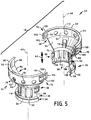
- FIGS. 1 to 4 illustrate one embodiment of a lamp assembly 10 of the present invention.
- Lamp assembly 10 comprises a lamp subassembly 12, which includes a lamp 14 coupled to a reflector 16, and a lamp coupler 18.
- coupler 18 may be molded from a resin material.
- the lamp 14 may be a conventional high intensity discharge lamp which includes an arc tube 20 contained within a glass envelope 22 which is attached to an insulative lamp base 24 fabricated from a resin material in a conventional manner.
- one example of such a lamp is the standard high intensity discharge (HID) 35 W HID D2 lamp manufactured by Osram Sylvania Inc.
- the reflector 16 includes a body 26. Without limitation, the body 26 may be fabricated from glass or molded from a resin material.
- the reflector body 26 includes a reflective surface 28 which reflects light emitted by the arc of the arc tube in a conventional manner.
- the lamp 14 and reflector 16 are initially coupled together by inserting the envelope 22 through an opening 30 which extends through the reflector.
- the outer diameter of the tubular envelope 22 and the width 32 of the opening 30 may be such that the envelope may be freely moved within the opening.
- the coupler 18 is provided in order to obtain optimal positioning of the arc of the arc tube 20 relative to the reflector 16.
- the coupler 18 facilitates positioning of the lamp 14 relative to the reflector 16 while inserting the envelope 22 within opening 30 so that the light source or arc of the arc tube 20 will be positioned relative to the reflector along reflector axis 34 to obtain maximum average lumen output from the lamp assembly, as described hereinafter.
- the reflective surface 28 is symmetrical relative to axis 34.
- the coupler includes a first portion which engages the lamp and a second portion which engages the reflector, the first and second portions being structured and arranged to position the light source along the reflector axis, as desired.
- the coupler of the present invention may comprise a first portion formed by one interior surface of the coupler at least a portion of which is adapted to engage at least a portion of an exterior surface of the lamp 14, and a second portion formed by another interior surface of the coupler at least a portion of which is adapted to engage at least a portion of an exterior surface of the reflector 16.
- first and second portions are structured and arranged such that the first portion conformally mates with a segment of the lamp 14 and the second portion conformally mates with a segment of the reflector 16 to position the light source or arc of the arc tube 20 along the reflector axis 34 to obtain maximum average lumen output of the lamp assembly 10.
- the first and second portions of the coupler 18 are formed by first portions 36 and second portions 38 of a first coupler segment 40 and a second coupler segment 42.
- the coupler segments 40 and 42 are substantially identical, except as described herein.
- each coupler segment 40, 42 extends in the direction 44 of a coupler axis 46 from a front coupler end 48 to a rear coupler end 50.
- the coupler segments 40,42 are assembled with the lamp/reflector subassembly 12, the respective coupler axes 46 will be coincident with each other and with the reflector axis 34.
- the coupler segments 40,42 are structured and arranged to enclose the lamp 14 and reflector 16 when the coupler segments are latched together, as described hereinafter.
- each second portion 38 of each coupler segment 40, 42 comprises a semi-cylindrical wall 52 which is parallel to the axis 46 and includes a flanged region 54 including a flange extending towards axis 46 at the front coupler end 48.
- Each first portion 36 of each coupler segment 40,42 comprises a semi-cylindrical wall 56 which is parallel to the axis 46 and includes a recess 58 which opens towards axis 46 at the rear coupler end 50.
- the walls 52 and 56 have respective diameters of 60 (FIG. 2) and 62 (FIG. 1), the diameter 62 being less than the diameter 60.
- the walls 52 and 56 are joined by a bridging wall 64 which extends at an angle relative to axis 46.
- the coupler 18 When the coupler segments 40, 42 are latched together as described herein, the coupler 18 will be completed and will include a circumferentially extending flanged portion 54 and a circumferentially extending recess 58.
- the circumferentially extending flanged portion 54 formed by coupler segments 40,42 will conformally mate with a circumferentially extending front edge 66 of the reflector 16.
- the circumferentially extending recess 58 formed by coupler segments 40,42 will conformally mate with a circumferentially extending base flange 68 of the lamp base 24 of lamp 14 to hold the lamp in place relative to the coupler.
- the coupler of the present invention comprises a resilient third portion positioned between the first and second coupler portions, such third portion being structured and arranged to be biased against an external surface of the reflector when the coupler is coupled to the lamp/reflector subassembly to thereby urge the reflector against the second portion of the coupler.
- each coupler segment comprises a third portion in the form of a plurality of resilient fingers 70 which extend from the bridging wall 64 towards the coupler axis 46.
- the resilient fingers 70 are structured and arranged such that when the coupler segments 40,42 are coupled to the lamp/reflector subassembly, the fingers (a) form the third portion of the coupler and (b) are depressed by the exterior surface 72 of the reflector 16 and thereby biased against the exterior surface of the reflector. In this manner, the fingers 70 will urge the front edge 66 of the reflector 16 against the surface 74 of coupler flange 54 thereby holding the reflector in place relative to the coupler 18. Since the fingers 70 serve to hold the reflector 16 in place relative to the coupler 18, and the mating of the recess 58 and lamp base flange 68 serves to hold the lamp 14 in place relative to the coupler, the reflector and lamp will be held in place relative to each other.
- the coupler segments of the present invention are structured and arranged to be latched together when they are coupled to a lamp/reflector subassembly.
- one coupler segment may include one or more latch which mates with a respective one or more mating latch of the other coupler segment to latch the coupler segments together.
- the coupler segments of the present invention may encircle a portion of the lamp and/or a portion of the reflector.
- the coupler segments 40,42 may be latched together to encircle a portion of the lamp 14 and a portion of reflector 16 as illustrated in the drawings.
- each coupler segment 40,42 comprises a first latch 76 and a second latch 78 adjacent respective first and second interface surfaces 80 and 82 at respective opposite edges 84 and 86 of the semi-cylindrical wall 52.
- each coupler segment 40,42 comprises a third latch 88 and a fourth latch 90 adjacent respective third and fourth interface surfaces 92 and 94 at respective edges 96 and 98 of the semi-cylindrical wall 56.
- each latch 76 may comprise resilient arms 100,102 which are cantilevered from the wall 52 at edge 84 and are joined by a bridge member 104.
- Each latch 78 is in the form of a ramp having a ramp surface 106 and an abutment surface 108.
- each latch 76 will engage a respective latch 78.
- latches 76 and 78 are structured and arranged such that the bridge member 104 will engage a ramp surface 106 and thereby flex away from the coupler axis 46 until the coupler segments 40,42 are completely assembled to form the coupler 18, at which time the ramp will extend between the resilient arms 100, 102 as the arms resile towards the coupler axis. In this manner, the bridge member 104 engages the abutment surface 108 to lock the coupler segments together.
- the latches 88 and 90 are identical to, and function in the same manner as, the latches 76 and 78, with the exception that latches 88 and 90 are somewhat shorter in length than latches 76 and 78.
- Each coupler segment 40,42 may include openings such as circular openings 114 and elongated openings 116. Such openings provide ventilation for the lamp assembly 12 enclosed by the coupler 18.
- lamp base 24 comprises at least one dimple 118 protruding from the base flange 68.
- Each dimple 118 engages a reference surface 122 of the recess 58.
- the surface 126 of the base flange 68 engages the reference surface 122.
- surface 122 of recess 58 provides a reference surface for the base 68 useful in locating the arc 116 relative to the axis 34; that is, the engagement of the lamp base 68 within the coupler recess 58 will hold the lamp 14 in place relative to the coupler at the desired location along axis 34.
- the distance 130 between the flange surface 74, which provides a reflector reference surface, and the surface 122 will determine the position of the reflector 16 along axis 34.
- the engagement of the front edge 66 of the reflector 16 with the surface 74 will fix the position of the reflective surface 28 relative to the reflector axis 34.
- the resilient fingers 70 urge the reflector 16 against surface 74 thereby holding the reflector in place relative to the coupler 18 and the arc 116 of the lamp 12 to fix the position of the reflective surface 28 relative to the arc along axis 34.
- the reflector will be axially symmetrical relative to the coupler axis 46, axis 46 being coincident with axis 34.
- the reflector 16 has a second reflector axis 132 which is perpendicular to the first reflector axis 34.
- axis 34 is referred to as the horizontal reflector axis
- axis 132 is referred to as the vertical reflector axis.
- the light source or arc 116 of the lamp 14 is positioned along axis 132.
- Lamp axis 120, and therefore arc 116, is also offset a distance 134 relative to the axis 34. Such offset may be desirable in order to compensate for the bowed arc characteristically present in some lamps.
- each first portion 36 of the coupler 18 comprises a first interior surface of the coupler which is asymmetrical relative to the coupler axis 46
- each second portion 38 of the coupler 18 comprises a second interior surface of the coupler which is symmetrical relative to the coupler axis.
- each first interior surface mates with the lamp and each second interior surface mates with the reflector.
- the recesses 58 combine to form a circumferentially extending base surface 138 which is asymmetrical relative to the coupler axis 46.
- a circumferentially extending coupler inner surface 140 is formed which is symmetrical relative to the coupler axis 46.
- the lamp base 68 is provided with a keyway 144 which mates with a key 146 extending from the coupler base surface 138 of one of the coupler segments. Since the lamp base 68 includes only one keyway 144, only one coupler segment need be provided with a mating key 146. In the embodiment illustrated in the drawings only coupler segment 40 is provided with a mating key 146, and to this extent coupler segment 40 differs from coupler segment 42.
- each coupler segment 40 may include a plurality of tabs 148 which extend towards coupler axis 46 and are spaced from the inner surface 74 of the flanged region 54.
- the front end of the reflector may include a flanged region 150 which includes the front edge 66 and portion 142.
- the flanged region 150 may be inserted between the surface 74 and the tabs 148.
- the lamp 14 is rotated relative to the lamp axis 120 until the key 146 extends into the keyway 144.
- the coupler segment 42 is coupled to the lamp subassembly 12 and coupler segment 40 by inserting the subassembly into the coupler segment 42 such that the base 68 mates with recess 58 of coupler segment 42, including coupler base surface 138, and the portion 142 of the outer reflector surface 72 engages the coupler inner surface 140.
- the flanged region 150 of the reflector is inserted between surface 74 and the tabs 148 of coupler 42.
- the coupler segments 40 and 42 are latched together as described herein.
- Such latching operation causes the resilient fingers 70 to be depressed by exterior surface 72 of reflector 16 and thereby be biased against the surface 72 to urge the front edge 66 of the reflector against the surface 74 of the flanged region 54 thereby holding the reflector in place relative to the coupler 18 and the lamp 14.
- the arc 116 Upon assembly in this manner, the arc 116 will be positioned along reflector axis 34, and offset along reflector axis 132 a distance 134, to provide optimum focussing.
- Enclosing the lamp subassembly 12 within the coupling halves 40,42, and latching the coupling halves together thereby forming the coupler 18, permits easy assembly of the components and provides a manner which (a) readily and accurately fixes the position of the light source relative to the reflector along the horizontal and vertical axes of the reflector to obtain maximum average lumen output from the lamp assembly, and (b) does not require a costly lamp to reflector focusing operation.
- the actual focussed location of the light source relative to the reflector will depend upon the nature of the particular lamp and reflector being used and can be determined in a conventional manner.
Landscapes
- Engineering & Computer Science (AREA)
- General Engineering & Computer Science (AREA)
- Fastening Of Light Sources Or Lamp Holders (AREA)
- Non-Portable Lighting Devices Or Systems Thereof (AREA)
- Arrangement Of Elements, Cooling, Sealing, Or The Like Of Lighting Devices (AREA)
- Vessels And Coating Films For Discharge Lamps (AREA)
- Connecting Device With Holders (AREA)
Applications Claiming Priority (2)
| Application Number | Priority Date | Filing Date | Title |
|---|---|---|---|
| US09/598,548 US6402348B1 (en) | 2000-06-21 | 2000-06-21 | Lamp assembly and coupler |
| US598548 | 2000-06-21 |
Publications (3)
| Publication Number | Publication Date |
|---|---|
| EP1167876A2 true EP1167876A2 (de) | 2002-01-02 |
| EP1167876A3 EP1167876A3 (de) | 2004-04-21 |
| EP1167876B1 EP1167876B1 (de) | 2005-10-05 |
Family
ID=24395998
Family Applications (1)
| Application Number | Title | Priority Date | Filing Date |
|---|---|---|---|
| EP01115120A Expired - Lifetime EP1167876B1 (de) | 2000-06-21 | 2001-06-21 | Lampenanordnung und Koppelungselement |
Country Status (6)
| Country | Link |
|---|---|
| US (1) | US6402348B1 (de) |
| EP (1) | EP1167876B1 (de) |
| AT (1) | ATE306048T1 (de) |
| CA (1) | CA2344285A1 (de) |
| DE (1) | DE60113774T2 (de) |
| ES (1) | ES2246276T3 (de) |
Families Citing this family (4)
| Publication number | Priority date | Publication date | Assignee | Title |
|---|---|---|---|---|
| JP3353774B2 (ja) * | 2000-03-17 | 2002-12-03 | ウシオ電機株式会社 | ランプユニット |
| US7121691B2 (en) * | 2004-09-22 | 2006-10-17 | Osram Sylvania Inc. | Lamp assembly with interchangeable light distributing cap |
| JP5410986B2 (ja) * | 2006-12-11 | 2014-02-05 | コーニンクレッカ フィリップス エヌ ヴェ | 電気反射形ランプ |
| JP5702800B2 (ja) * | 2009-11-27 | 2015-04-15 | コーニンクレッカ フィリップス エヌ ヴェ | 電気反射器ランプ及び反射器 |
Family Cites Families (6)
| Publication number | Priority date | Publication date | Assignee | Title |
|---|---|---|---|---|
| US5465025A (en) * | 1993-05-10 | 1995-11-07 | Litetronics International, Inc. | Lamp with removable base and replaceable bulb capsule |
| EP0629816B1 (de) * | 1993-06-15 | 2000-07-12 | Curtis J. Carley | Glühlampe mit Reflektorsystem und Verfahren zu deren Herstellung |
| EP0662584B1 (de) * | 1994-01-07 | 1997-11-05 | Leclanché S.A. | Lampenfassung und Taschenlampe mit einer solchen Fassung |
| US5506471A (en) * | 1994-06-06 | 1996-04-09 | General Electric Company | Low glare infrared light source |
| DE29602924U1 (de) * | 1996-02-19 | 1996-04-18 | Hsu Yuan Shun | Lampenfassung für eine Dekorations-Lichterkette |
| CN1123035C (zh) * | 1996-09-11 | 2003-10-01 | 皇家菲利浦电子有限公司 | 照明装置 |
-
2000
- 2000-06-21 US US09/598,548 patent/US6402348B1/en not_active Expired - Fee Related
-
2001
- 2001-04-18 CA CA002344285A patent/CA2344285A1/en not_active Abandoned
- 2001-06-21 AT AT01115120T patent/ATE306048T1/de not_active IP Right Cessation
- 2001-06-21 EP EP01115120A patent/EP1167876B1/de not_active Expired - Lifetime
- 2001-06-21 DE DE60113774T patent/DE60113774T2/de not_active Expired - Fee Related
- 2001-06-21 ES ES01115120T patent/ES2246276T3/es not_active Expired - Lifetime
Non-Patent Citations (1)
| Title |
|---|
| None |
Also Published As
| Publication number | Publication date |
|---|---|
| US6402348B1 (en) | 2002-06-11 |
| ES2246276T3 (es) | 2006-02-16 |
| ATE306048T1 (de) | 2005-10-15 |
| EP1167876B1 (de) | 2005-10-05 |
| CA2344285A1 (en) | 2001-12-21 |
| DE60113774D1 (de) | 2005-11-10 |
| EP1167876A3 (de) | 2004-04-21 |
| DE60113774T2 (de) | 2006-03-16 |
Similar Documents
| Publication | Publication Date | Title |
|---|---|---|
| US5281889A (en) | Reflector lamp having a light-source capsule secured between mating neck and reflector bodies | |
| NZ229262A (en) | Lamp reflector: heat shield extends into central hole | |
| US6382818B1 (en) | Lighting device for a vehicle | |
| US5727869A (en) | Fluorescent light fixture with breakaway socket | |
| WO2007118044A1 (en) | High-intensity discharge lamp for spot lighting | |
| US6402348B1 (en) | Lamp assembly and coupler | |
| US4608624A (en) | Projection lamp unit with separable lamp capsule | |
| US5367219A (en) | Electric reflector lamp for use with IEC standard | |
| EP0053782B1 (de) | Projektionseinrichtung mit einem Glasreflektor | |
| US20030151919A1 (en) | Bulb cooling | |
| JP2003263917A (ja) | 照明器具 | |
| US5130910A (en) | Reflective housing for increased luminance of fluorescent bulbs | |
| CN111999845B (zh) | 镜头模组 | |
| JP4089498B2 (ja) | 無電極放電灯 | |
| EP0063310B1 (de) | Beleuchtungseinrichtung mit auswechselbarer Lampe und gleitendem Lampenausheber | |
| JPH04229944A (ja) | プレスシール形態を有するアパーチャ付き蛍光ランプ | |
| US6267489B1 (en) | Vehicular headlamp having improved bulb support | |
| JP2006294638A (ja) | 照明器具 | |
| KR200325474Y1 (ko) | 벌브홀더를 갖춘 차량 전조등용 가스방전램프 | |
| CN220707210U (zh) | 筒灯安装结构和筒灯 | |
| JP2558982Y2 (ja) | 車両用灯具 | |
| HU202312B (en) | Lamp-reflector unit | |
| EP0543448A1 (de) | Elektrische Reflektorlampe | |
| KR100322048B1 (ko) | 반사 코팅막을 갖는 비대칭 방전램프 | |
| JP5054571B2 (ja) | ランプの固定構造 |
Legal Events
| Date | Code | Title | Description |
|---|---|---|---|
| PUAI | Public reference made under article 153(3) epc to a published international application that has entered the european phase |
Free format text: ORIGINAL CODE: 0009012 |
|
| AK | Designated contracting states |
Kind code of ref document: A2 Designated state(s): AT BE CH CY DE DK ES FI FR GB GR IE IT LI LU MC NL PT SE TR |
|
| AX | Request for extension of the european patent |
Free format text: AL;LT;LV;MK;RO;SI |
|
| PUAL | Search report despatched |
Free format text: ORIGINAL CODE: 0009013 |
|
| AK | Designated contracting states |
Kind code of ref document: A3 Designated state(s): AT BE CH CY DE DK ES FI FR GB GR IE IT LI LU MC NL PT SE TR |
|
| AX | Request for extension of the european patent |
Extension state: AL LT LV MK RO SI |
|
| 17P | Request for examination filed |
Effective date: 20040517 |
|
| AKX | Designation fees paid |
Designated state(s): AT BE CH CY DE DK ES FI FR GB GR IE IT LI LU MC NL PT SE TR |
|
| 17Q | First examination report despatched |
Effective date: 20040804 |
|
| GRAP | Despatch of communication of intention to grant a patent |
Free format text: ORIGINAL CODE: EPIDOSNIGR1 |
|
| GRAS | Grant fee paid |
Free format text: ORIGINAL CODE: EPIDOSNIGR3 |
|
| GRAA | (expected) grant |
Free format text: ORIGINAL CODE: 0009210 |
|
| AK | Designated contracting states |
Kind code of ref document: B1 Designated state(s): AT BE CH CY DE DK ES FI FR GB GR IE IT LI LU MC NL PT SE TR |
|
| PG25 | Lapsed in a contracting state [announced via postgrant information from national office to epo] |
Ref country code: AT Free format text: LAPSE BECAUSE OF FAILURE TO SUBMIT A TRANSLATION OF THE DESCRIPTION OR TO PAY THE FEE WITHIN THE PRESCRIBED TIME-LIMIT Effective date: 20051005 Ref country code: CH Free format text: LAPSE BECAUSE OF FAILURE TO SUBMIT A TRANSLATION OF THE DESCRIPTION OR TO PAY THE FEE WITHIN THE PRESCRIBED TIME-LIMIT Effective date: 20051005 Ref country code: LI Free format text: LAPSE BECAUSE OF FAILURE TO SUBMIT A TRANSLATION OF THE DESCRIPTION OR TO PAY THE FEE WITHIN THE PRESCRIBED TIME-LIMIT Effective date: 20051005 Ref country code: FI Free format text: LAPSE BECAUSE OF FAILURE TO SUBMIT A TRANSLATION OF THE DESCRIPTION OR TO PAY THE FEE WITHIN THE PRESCRIBED TIME-LIMIT Effective date: 20051005 |
|
| REG | Reference to a national code |
Ref country code: GB Ref legal event code: FG4D |
|
| REG | Reference to a national code |
Ref country code: CH Ref legal event code: EP |
|
| REG | Reference to a national code |
Ref country code: IE Ref legal event code: FG4D |
|
| REF | Corresponds to: |
Ref document number: 60113774 Country of ref document: DE Date of ref document: 20051110 Kind code of ref document: P |
|
| PG25 | Lapsed in a contracting state [announced via postgrant information from national office to epo] |
Ref country code: GR Free format text: LAPSE BECAUSE OF FAILURE TO SUBMIT A TRANSLATION OF THE DESCRIPTION OR TO PAY THE FEE WITHIN THE PRESCRIBED TIME-LIMIT Effective date: 20060105 Ref country code: SE Free format text: LAPSE BECAUSE OF FAILURE TO SUBMIT A TRANSLATION OF THE DESCRIPTION OR TO PAY THE FEE WITHIN THE PRESCRIBED TIME-LIMIT Effective date: 20060105 Ref country code: DK Free format text: LAPSE BECAUSE OF FAILURE TO SUBMIT A TRANSLATION OF THE DESCRIPTION OR TO PAY THE FEE WITHIN THE PRESCRIBED TIME-LIMIT Effective date: 20060105 |
|
| REG | Reference to a national code |
Ref country code: ES Ref legal event code: FG2A Ref document number: 2246276 Country of ref document: ES Kind code of ref document: T3 |
|
| PG25 | Lapsed in a contracting state [announced via postgrant information from national office to epo] |
Ref country code: PT Free format text: LAPSE BECAUSE OF FAILURE TO SUBMIT A TRANSLATION OF THE DESCRIPTION OR TO PAY THE FEE WITHIN THE PRESCRIBED TIME-LIMIT Effective date: 20060306 |
|
| REG | Reference to a national code |
Ref country code: CH Ref legal event code: PL |
|
| ET | Fr: translation filed | ||
| PGFP | Annual fee paid to national office [announced via postgrant information from national office to epo] |
Ref country code: GB Payment date: 20060613 Year of fee payment: 6 |
|
| PGFP | Annual fee paid to national office [announced via postgrant information from national office to epo] |
Ref country code: NL Payment date: 20060616 Year of fee payment: 6 |
|
| PGFP | Annual fee paid to national office [announced via postgrant information from national office to epo] |
Ref country code: BE Payment date: 20060620 Year of fee payment: 6 |
|
| PG25 | Lapsed in a contracting state [announced via postgrant information from national office to epo] |
Ref country code: IE Free format text: LAPSE BECAUSE OF NON-PAYMENT OF DUE FEES Effective date: 20060621 |
|
| PGFP | Annual fee paid to national office [announced via postgrant information from national office to epo] |
Ref country code: FR Payment date: 20060623 Year of fee payment: 6 |
|
| PG25 | Lapsed in a contracting state [announced via postgrant information from national office to epo] |
Ref country code: MC Free format text: LAPSE BECAUSE OF NON-PAYMENT OF DUE FEES Effective date: 20060630 |
|
| PGFP | Annual fee paid to national office [announced via postgrant information from national office to epo] |
Ref country code: IT Payment date: 20060630 Year of fee payment: 6 |
|
| PGFP | Annual fee paid to national office [announced via postgrant information from national office to epo] |
Ref country code: ES Payment date: 20060718 Year of fee payment: 6 |
|
| PLBE | No opposition filed within time limit |
Free format text: ORIGINAL CODE: 0009261 |
|
| STAA | Information on the status of an ep patent application or granted ep patent |
Free format text: STATUS: NO OPPOSITION FILED WITHIN TIME LIMIT |
|
| PGFP | Annual fee paid to national office [announced via postgrant information from national office to epo] |
Ref country code: DE Payment date: 20060821 Year of fee payment: 6 |
|
| 26N | No opposition filed |
Effective date: 20060706 |
|
| REG | Reference to a national code |
Ref country code: IE Ref legal event code: MM4A |
|
| BERE | Be: lapsed |
Owner name: *OSRAM SYLVANIA INC. Effective date: 20070630 |
|
| GBPC | Gb: european patent ceased through non-payment of renewal fee |
Effective date: 20070621 |
|
| NLV4 | Nl: lapsed or anulled due to non-payment of the annual fee |
Effective date: 20080101 |
|
| PG25 | Lapsed in a contracting state [announced via postgrant information from national office to epo] |
Ref country code: BE Free format text: LAPSE BECAUSE OF NON-PAYMENT OF DUE FEES Effective date: 20070630 |
|
| REG | Reference to a national code |
Ref country code: FR Ref legal event code: ST Effective date: 20080229 |
|
| PG25 | Lapsed in a contracting state [announced via postgrant information from national office to epo] |
Ref country code: DE Free format text: LAPSE BECAUSE OF NON-PAYMENT OF DUE FEES Effective date: 20080101 Ref country code: NL Free format text: LAPSE BECAUSE OF NON-PAYMENT OF DUE FEES Effective date: 20080101 |
|
| PG25 | Lapsed in a contracting state [announced via postgrant information from national office to epo] |
Ref country code: GB Free format text: LAPSE BECAUSE OF NON-PAYMENT OF DUE FEES Effective date: 20070621 |
|
| PG25 | Lapsed in a contracting state [announced via postgrant information from national office to epo] |
Ref country code: LU Free format text: LAPSE BECAUSE OF NON-PAYMENT OF DUE FEES Effective date: 20060621 Ref country code: TR Free format text: LAPSE BECAUSE OF FAILURE TO SUBMIT A TRANSLATION OF THE DESCRIPTION OR TO PAY THE FEE WITHIN THE PRESCRIBED TIME-LIMIT Effective date: 20051005 |
|
| REG | Reference to a national code |
Ref country code: ES Ref legal event code: FD2A Effective date: 20070622 |
|
| PG25 | Lapsed in a contracting state [announced via postgrant information from national office to epo] |
Ref country code: FR Free format text: LAPSE BECAUSE OF NON-PAYMENT OF DUE FEES Effective date: 20070702 |
|
| PG25 | Lapsed in a contracting state [announced via postgrant information from national office to epo] |
Ref country code: ES Free format text: LAPSE BECAUSE OF NON-PAYMENT OF DUE FEES Effective date: 20070622 |
|
| PG25 | Lapsed in a contracting state [announced via postgrant information from national office to epo] |
Ref country code: CY Free format text: LAPSE BECAUSE OF FAILURE TO SUBMIT A TRANSLATION OF THE DESCRIPTION OR TO PAY THE FEE WITHIN THE PRESCRIBED TIME-LIMIT Effective date: 20051005 |
|
| PG25 | Lapsed in a contracting state [announced via postgrant information from national office to epo] |
Ref country code: IT Free format text: LAPSE BECAUSE OF NON-PAYMENT OF DUE FEES Effective date: 20070621 |