EP1167855A2 - Steckverbindung zwischen einem ringgewellten Schlauch und einem Glattrohr - Google Patents
Steckverbindung zwischen einem ringgewellten Schlauch und einem Glattrohr Download PDFInfo
- Publication number
- EP1167855A2 EP1167855A2 EP01115048A EP01115048A EP1167855A2 EP 1167855 A2 EP1167855 A2 EP 1167855A2 EP 01115048 A EP01115048 A EP 01115048A EP 01115048 A EP01115048 A EP 01115048A EP 1167855 A2 EP1167855 A2 EP 1167855A2
- Authority
- EP
- European Patent Office
- Prior art keywords
- hose
- holding element
- plug connection
- connection according
- ring
- Prior art date
- Legal status (The legal status is an assumption and is not a legal conclusion. Google has not performed a legal analysis and makes no representation as to the accuracy of the status listed.)
- Granted
Links
- 210000002105 tongue Anatomy 0.000 claims description 25
- 238000007789 sealing Methods 0.000 claims description 21
- 229910001369 Brass Inorganic materials 0.000 claims description 4
- 239000010951 brass Substances 0.000 claims description 4
- 238000006073 displacement reaction Methods 0.000 claims description 4
- 229910001220 stainless steel Inorganic materials 0.000 claims description 4
- 239000010935 stainless steel Substances 0.000 claims description 4
- 238000011144 upstream manufacturing Methods 0.000 claims description 4
- 229910000639 Spring steel Inorganic materials 0.000 claims description 2
- 239000000853 adhesive Substances 0.000 claims description 2
- 230000001070 adhesive effect Effects 0.000 claims description 2
- 239000002184 metal Substances 0.000 description 6
- 229910052751 metal Inorganic materials 0.000 description 6
- 238000003780 insertion Methods 0.000 description 5
- 230000037431 insertion Effects 0.000 description 5
- 238000004519 manufacturing process Methods 0.000 description 5
- 239000000463 material Substances 0.000 description 4
- 230000000694 effects Effects 0.000 description 3
- RYGMFSIKBFXOCR-UHFFFAOYSA-N Copper Chemical compound [Cu] RYGMFSIKBFXOCR-UHFFFAOYSA-N 0.000 description 1
- 229910052802 copper Inorganic materials 0.000 description 1
- 239000010949 copper Substances 0.000 description 1
- 230000006378 damage Effects 0.000 description 1
- 239000003292 glue Substances 0.000 description 1
- 238000007689 inspection Methods 0.000 description 1
- 210000001503 joint Anatomy 0.000 description 1
- 238000012423 maintenance Methods 0.000 description 1
- 230000002265 prevention Effects 0.000 description 1
- 239000000565 sealant Substances 0.000 description 1
Images

Classifications
-
- F—MECHANICAL ENGINEERING; LIGHTING; HEATING; WEAPONS; BLASTING
- F16—ENGINEERING ELEMENTS AND UNITS; GENERAL MEASURES FOR PRODUCING AND MAINTAINING EFFECTIVE FUNCTIONING OF MACHINES OR INSTALLATIONS; THERMAL INSULATION IN GENERAL
- F16L—PIPES; JOINTS OR FITTINGS FOR PIPES; SUPPORTS FOR PIPES, CABLES OR PROTECTIVE TUBING; MEANS FOR THERMAL INSULATION IN GENERAL
- F16L25/00—Construction or details of pipe joints not provided for in, or of interest apart from, groups F16L13/00 - F16L23/00
- F16L25/0036—Joints for corrugated pipes
- F16L25/0045—Joints for corrugated pipes of the quick-acting type
-
- F—MECHANICAL ENGINEERING; LIGHTING; HEATING; WEAPONS; BLASTING
- F16—ENGINEERING ELEMENTS AND UNITS; GENERAL MEASURES FOR PRODUCING AND MAINTAINING EFFECTIVE FUNCTIONING OF MACHINES OR INSTALLATIONS; THERMAL INSULATION IN GENERAL
- F16L—PIPES; JOINTS OR FITTINGS FOR PIPES; SUPPORTS FOR PIPES, CABLES OR PROTECTIVE TUBING; MEANS FOR THERMAL INSULATION IN GENERAL
- F16L33/00—Arrangements for connecting hoses to rigid members; Rigid hose-connectors, i.e. single members engaging both hoses
- F16L33/26—Arrangements for connecting hoses to rigid members; Rigid hose-connectors, i.e. single members engaging both hoses specially adapted for hoses made of metal
Definitions
- the invention relates to a plug connection between a ring-corrugated Hose and a smooth pipe, with the hose end surrounding the smooth pipe Holding element for holding the smooth tube connected at least indirectly and the smooth tube end of at least one of the holding element in the direction is encased on the hose upstream sealing ring, which in turn is at least indirectly sealingly connected to the hose.
- Such a plug connection results, among other things, from assembly or revision reasons, if components flow through a medium during your assembly first connected and then brought into place, for example, folded or when such components are replaced or for inspection or maintenance must be removed from their working position. In all cases the named component must still after establishing the flow connection are moved, which is why in the flow connection the above Corrugated hose sits as a flexible element.
- the connector serves the easy establishment of the flow connection by simply inserting the For example, the end of the smooth pipe on the component side is connected to the corrugated hose Holding element so that a tight flow path is created without that the use of assembly tools etc. was still required.
- metal is usually found as the material, in particular stainless steel or copper use. Depending on the peculiarities of the In individual cases, however, the use of plastic can also be sufficient or be appropriate.
- the object of the invention is therefore a plug connection of the aforementioned Kind of different in that the number of components required and sealing points and the space required for this considerably reduced respective plug connection is significantly simplified, so that there is a noticeable Reduction of the production costs for one with connections for a plug connection provided corrugated hose results.
- This object is achieved in that the holding element in Hose end arranged and from this by mutual positive Connection is held at least in the axial direction, and that the sealing ring in a shaft of the hose located next to the holding element is inserted from the inside is.
- the holding element As far as the form fit between the holding element and hose end, so can basically any corresponding profiles of Hose end on the one hand and the outer contour of the holding element on the other hand be engaged.
- the holding element an essentially corrugated outer profile in correspondence to Has ring corrugation of the hose, advantageously with the holding element corresponding part of the hose end in the direction of a flattening the hose shafts are stretched.
- the option can also be used are to form the holding element as a component injected into the hose end.
- the holding element is one Has longitudinal slot forming axially parallel gap and in the hose end inserted by the gap width with an elastic reduction in cross-section and is then blown in by resilient expansion.
- the holding element can be provided consists of two axially parallel half shells, where the joint width is dimensioned such that the half-shells at least one after the other can be inserted into the hose end. The final seat of these half shells then results when the smooth tube is inserted, which prevents the Half shells fall out of their positive connection with the hose end can.
- the sealing ring As for the sealing ring, this is usually before the mounting of the holding element already be used in the corrugated hose, for which there is no special Measures are required because the corrugated profile of the hose with a suitable, next to the holding element already positioned hose shaft Inclusion of the sealing ring forms the required chamber.
- the holding element As far as the design of the holding element is concerned, there are also numerous here Possibilities that the smooth tube end through the holding element coaxial led to the hose and at least to some extent against an unintended Slipping out of the holding element is jammed with this.
- a design according to the invention has proven to be advantageous that the holding element, starting from a seated in the hose end, over the circumference closed axial ring section evenly over the circumference distributes axially in the direction of the hose extending holding fingers for frictional Has locking of the smooth tube end. It can be provided that the holding fingers are resiliently radially movable within limits and with their ends after radially inclined are formed.
- a predetermined holding force in the sense of generation Dimension is smaller than the outer diameter of the smooth pipe end. In both In some cases, this has the effect of holding fingers when inserting the smooth pipe end radially resiliently spread and then under the springback force thus generated rest on the outside of the smooth tube end, so that between there is sufficient frictional engagement between the holding fingers and the smooth tube end, to prevent the smooth pipe end from slipping out accidentally or too easily to prevent the holding element.
- the holding element used a spring ring with evenly distributed over the circumference, spring tongues which extend obliquely in the direction of the hose and extend radially inwards and that the circumscribed by the free ends of the spring tongues Cross section is less than the outer cross section of the smooth tube.
- the spring tongues are initially radial spread outwards until the smooth pipe end can pass underneath them. Due to the inclination of the spring tongues, however, the free tongues get caught Front edges with the outer surface of the smooth tube end, so that its pulling out from the holding element is practically only possible with the use of force. To achieve this effect, it is particularly useful if the spring ring consists of spring steel sheet.
- the spring tongues of an essentially hollow cylindrical extend axially parallel supporting part of the spring washer, and that the Support part is anchored in the holding element.
- the holding element for example consist of two annular parts, with the interposition of the supporting part of the spring ring can be plugged together.
- the holding element consists of a Plastic part, so there is also the possibility of the support part of the spring ring to be injected in the manufacture of the plastic part.
- the above-described bracket for the smooth tube end initially is an intrinsically unsolvable connector. If you want this as for example for form a removable plug connection for the exchange of the connected component, so it is useful that between the spring tongues and plug-in Holding element section located at the end of the holding element is an enlargement its inner cross section for receiving an axially displaceable, hollow cylindrical Unlocking sleeve with the outer diameter of the smooth tube has the corresponding inner diameter that the unlocking sleeve Hose end protrudes outwards with one end, and that through the other End of the release sleeve with its axial displacement the spring tongues are pivotable radially outwards.
- one end of the Unlocking sleeve a handle in the form of a radially extending, from the hose end axially spaced collar.
- a handle in the form of a radially extending, from the hose end axially spaced collar.
- the unlocking sleeve next to its other End has a locking lug protruding radially outwards and the associated Holding element section adapted to it, up to the spring tongues extending recess to prevent accidental axial slipping out to prevent the release sleeve from the holding element.
- a detent and recess are circumferentially formed.
- the holding element and possibly the release sleeve are made of plastic, so a cheap, light component to be manufactured.
- at least the holding element is made of stainless steel or brass.
- the sealing ring in front of the holding element concerns there can be one available in any size on the market and therefore cheaper Use O-ring.
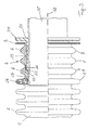
- Figures 1 and 3 show one end of a hose 1, for example made of metal with ring waves 2, the two waves closing the hose end into one Bund 3 are axially compressed.
- a holding element 4 made of plastic, for example axially adjoining annular holding element sections 5 and 6 consists.
- the holding element 4 forms a ring-corrugated over its sections 5 and 6 Outer contour on which the end of the hose 1 is shaped accordingly Ring shafts 7, 8, 9 is pressed, these ring shafts 7 to 9 being flatter and thus have a more elongated course than the other ring shafts 2 of the Hose 1.
- the mounting of the holding element 4 can be done by that the hose end is first expanded radially until the holding element 4 can be inserted axially. Then the hose end can be adjusted with the help of suitable Radial clamping means up to the shape shown in Figure 1 radial again are pressed together and onto the outer contour of the holding element 4.
- the Butt joint of the holding element sections 5, 6 formed such that the holding element section 6 with a circumferential collar 10 in a corresponding, circumferential Recess 11 of the holding element section 5 protrudes.
- the end 21 is with one after provided radially protruding, circumferential locking lug 22 (see in particular FIG. 2) which is fitted into a circumferential radial recess 23 that is adapted to it of the holding element part 6 protrudes, this recess 23 in the direction of Spring tongues 15 is open.
- the unlocking sleeve 19 In order to simplify the handling of the unlocking sleeve 19, it also has at its end 20 protruding from the hose end in Form of a radially outwardly extending, axially obstructed from the hose end Federal 24, which at the same time provides protection against the often sharp-edged represents hose end formed by the collar 3.
- a sealing ring 26 in the form of an O-ring is used, into which the front area of the smooth tube end 17 projects and thus for a gas or liquid-proof seal between hose 1 and smooth pipe 18 worries.
- the smooth tube 18 can have its end 17 be inserted into the holding element 4 until its end 17 in the Sealing ring 26 is immersed, the unlocking sleeve 19 counter to the direction of insertion is held back.
- the Spring tongues 15 of the spring ring 14 are pivoted radially outwards and slide with them their front edges 16 on the jacket of the smooth tube 18 until it stops comes. Then the front edges 16 of the spring tongues 15 are on the Smooth tube and hold this due to the inclined position of the spring 15 against unintentional pulling out firmly.
- the unlocking sleeve is used 19 shifted from right to left in relation to the drawing until its front edge pivots the spring tongues 15 radially outward Has. So that the smooth tube 18 from the locking action of the spring tongues 15 free and can be pulled out of the connection.
- the smooth tube 18 in a manner not shown on the Place be provided with a circumferential marking that when properly inserted The smooth pipe end sits next to the collar 24.
- a stop ring made of metal or plastic, for example use in the form of a snap ring the inside diameter appropriately corresponds to the inner diameter of the smooth tube 18 and consequently determines the depth at which the smooth tube 18 is inserted into the connection described can be.
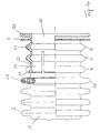
- Figure 4 shows a modified version of the connector, already objects described with reference to FIGS. 1 to 3 with the objects introduced there Numbered and are not described again.
- the holding element 30 consists of a form-fitting in the hose end seated and closed circumferential axial ring section 31, of which is evenly distributed axially towards the circumference extend on the hose 1 extending holding fingers 32, the relaxed in the The state of the free, internal cross-section is smaller than the external cross-section of the smooth tube, not shown. So that the holding fingers 32 in the radial direction slight, resilient pivoting movement are their front ends 33 against the wall of the hose 1 free.
- a smooth tube end in the substantially whose outer cross section corresponds to the inner cross section of the holding element 30 inserted the holding fingers 32 are pivoted slightly radially outward and lie with their cylindrical inner surface 34 on the jacket of the Smooth tube, so that they make the smooth tube through the manufactured in this way Hold the friction lock against unintentional pulling out.
- this connection is designed in such a way that with the corresponding Intent the smooth pipe against a certain resistance from the plug connection can be pulled out if this is described in detail at the beginning Reasons should be solved. Again serves as protection against injuries a collar 35 formed on the end of the holding element 30.
- the holding element 4 or 30 can be an inexpensive plastic part.
- metal for example stainless steel or brass.
- the seat of the holding element within the end of the hose 1 is described in the Way by positive locking the profile of the hose end with a appropriate profile of the holding element 4 and 30 given. To this To give the connection a greater hold, possibly also for prevention mutual twisting between hose 1 and holding element 4 or 30, the positive connection between these two parts another glue can be added.
Landscapes
- Engineering & Computer Science (AREA)
- General Engineering & Computer Science (AREA)
- Mechanical Engineering (AREA)
- Quick-Acting Or Multi-Walled Pipe Joints (AREA)
- Joints That Cut Off Fluids, And Hose Joints (AREA)
- Rigid Pipes And Flexible Pipes (AREA)
- Shaping Of Tube Ends By Bending Or Straightening (AREA)
Abstract
Description
- Figur 1
- ein Schlauchende mit einer ersten Ausführung einer Steckverbindung im axialen Halbschnitt;
- Figur 2
- die Einzelheit II aus Figur 1;
- Figur 3
- den Gegenstand gemäß Figur 1 mit eingestecktem Glattrohrende und
- Figur 4
- ein Schlauchende mit einer zweiten Bauform einer Steckverbindung im axialen Halbschnitt.
Claims (23)
- Steckverbindung zwischen einem ringgewellten Schlauch und einem Glattrohr, wobei mit dem Schlauchende ein das Glattrohr umgebendes Halteelement zum Festhalten des Glattrohres wenigstens mittelbar verbunden und das Glattrohrende von wenigstens einem dem Halteelement in Richtung auf den Schlauch vorgelagerten Dichtungsring umfangen ist, der seinerseits wenigstens mittelbar dichtend mit dem Schlauch in Verbindung steht,
dadurch gekennzeichnet, dass das Halteelement (4, 30) im Schlauchende angeordnet und von diesem durch gegenseitige formschlüssige Verbindung wenigstens in Axialrichtung gehalten ist, und dass der Dichtungsring (26) in eine neben dem Halteelement (4, 30) gelegene Welle (25) des Schlauches (1) von innen eingesetzt ist. - Steckverbindung nach Anspruch 1,
dadurch gekennzeichnet, dass das Halteelement (4, 30) eine im wesentlichen ringgewellte Außenprofilierung in Korrespondenz zur Ringwellung (7 bis 9) des Schlauches (1) aufweist. - Steckverbindung nach Anspruch 2,
dadurch gekennzeichnet, dass der mit dem Halteelement (4, 30) korrespondierende Teil des Schlauchendes in Richtung auf eine Abflachung der Schlauchwellen (7 bis 9) gestreckt ist. - Steckverbindung nach einem der Ansprüche 1 bis 3,
dadurch gekennzeichnet, dass das Schlauchende auf das Halteelement (4, 30) aufgepresst ist. - Steckverbindung nach einem der Ansprüche 1 bis 3,
dadurch gekennzeichnet, dass das Halteelement ein in das Schlauchende eingespritztes Bauteil ist. - Steckverbindung nach einem der Ansprüche 1 bis 3,
dadurch gekennzeichnet, dass das Haltelement eine einen achsparallelen Spalt bildende Längsschlitzung aufweist und in das Schlauchende bei elastischer Querschnittsverringerung um die Spaltbreite eingeschoben und anschließende durch elastisch rückfedernde Aufweitung eingesprengt ist. - Steckverbindung nach einem der Ansprüche 1 bis 3,
dadurch gekennzeichnet, dass das Halteelement aus zwei achsparallel voneinander getrennten Halteschalen besteht, wobei die Trennfugenbreite derart bemessen ist, dass die Halteschalen wenigstens nacheinander in das Schlauchende einsetzbar sind. - Steckverbindung nach einem der Ansprüche 1 bis 4,
dadurch gekennzeichnet, dass das Halteelement nach dem Einsetzen in das Schlauchende durch radiale Aufweitung mit diesem in formschlüssige Verbindung gebracht ist. - Steckverbindung nach einem der Ansprüche 1 bis 8,
dadurch gekennzeichnet, dass der formschlüssigen Verbindung zwischen Schlauchende und Halteelement (4, 30) ein Kleber zugefügt ist. - Steckverbindung nach einem der Ansprüche 1 bis 8,
dadurch gekennzeichnet, dass das Halteelement (30) ausgehend von einem im Schlauchende sitzenden, über den Umfang geschlossenen axialen Ringabschnitt (31) gleichmäßig über den Umfang verteilt sich axial in Richtung auf den Schlauch (1) erstreckende Haltefinger (32) zur reibschlüssigen Arretierung des Glattrohrendes aufweist. - Steckverbindung nach Anspruch 10,
dadurch gekennzeichnet, dass die Haltefinger (32) in Grenzen federnd radial beweglich und mit ihren Enden nach radial innen geneigt verlaufend ausgebildet sind. - Steckverbindung nach Anspruch 10,
dadurch gekennzeichnet, dass der von den Haltefingern (32) im entspannten Zustand umfangene Innendurchmesser um ein im Sinne der Erzeugung ausreichende Haltekräfte vorherbestimmtes Maß kleiner als der Außendurchmesser des Glattrohrendes ist. - Steckverbindung nach einem der Ansprüche 1 bis 8,
dadurch gekennzeichnet, dass das Halteelement (4) eingesetzt einen Federring (14) mit gleichmäßig über den Umfang verteilten, sich in Richtung auf den Schlauch (1) schräg nach radial innen erstreckenden Federzungen (15) aufweist, und dass der von den freien Enden (16) der Federzungen (15) umschriebene Querschnitt geringer als der Außenquerschnitt des Glattrohres (18) ist. - Steckverbindung nach Anspruch 13,
dadurch gekennzeichnet, dass die Federzungen (15) von einem im wesentlichen hohlzylindrischen, sich achsparallel erstreckenden Tragteil (13) des Federringes (14) ausgehen, und dass das Tragteil (13) im Halteelement (4) verankert ist. - Steckverbindung nach Anspruch 13 oder 14,
dadurch gekennzeichnet, dass der Federring (14) aus Federstahlblech besteht. - Steckverbindung nach einem der Ansprüche 13 bis 15,
dadurch gekennzeichnet, dass der zwischen Federzungen (15) und einsteckseitigem Ende des Halteelementes (4) gelegene Halteelementenabschnitt (6) eine Vergrößerung seines Innenquerschnittes zur Aufnahme einer darin axial verschiebbaren, hohlzylindrischen Entriegelungshülse (19) mit einem dem Außendurchmesser des Glattrohres (18) entsprechenden Innendurchmesser aufweist, dass die Entriegelungshülse (19) das Schlauchende nach außen mit ihrem einen Ende (20) überragt, und dass durch das andere Ende (21) der Entriegelungshülse (19) bei deren Axialverschiebung die Federzungen (15) radial nach außen schwenkbar sind. - Steckverbindung nach einem der vorhergehenden Ansprüche,
dadurch gekennzeichnet, dass das Halteelement (4) bzw. das eine Ende (20) der Entriegelungshülse (19) einen sich radial nach außen erstreckenden, vom Schlauchende axial beabstandeten Bund (24, 35) aufweist. - Steckverbindung nach Anspruch 16 oder 17,
dadurch gekennzeichnet, dass die Entriegelungshülse (19) neben ihrem anderen Ende (21) eine nach radial außen vorstehende Rastnase (22) aufweist und der Halteelementenabschnitt (6) eine daran angepasste, sich bis an die Federzungen (15) erstreckende Ausnehmung (23). - Steckverbindung nach Anspruch 18,
dadurch gekennzeichnet, dass Rastnase (22) und Ausnehmung (23) umlaufend ausgebildet sind. - Steckverbindung nach einem oder mehreren der Ansprüche 1 bis 19,
dadurch gekennzeichnet, dass das Halteelement (4, 30) und gegebenenfalls die Entriegelungshülse (19) aus Kunststoff bestehen. - Steckverbindung nach einem oder mehreren der Ansprüche 1 bis 19,
dadurch gekennzeichnet, dass wenigstens das Halteelement (4, 30) aus Edelstahl oder Messing besteht. - Steckverbindung nach einem oder mehreren der Ansprüche 1 bis 21,
dadurch gekennzeichnet, dass der dem Halteelement (4, 30) vorgelagerte Dichtungsring ein O-Ring ist. - Steckverbindung nach einem oder mehreren der Ansprüche 1 bis 22,
dadurch gekennzeichnet, dass dem Dichtungsring (26) in Richtung auf den Schlauch (1) ein Anschlagring für das Glattrohr (18) vorgelagert ist, und dass der Anschlagring in eine neben dem Dichtungsring gelegene Welle des Schlauches (1) von innen eingesetzt ist.
Applications Claiming Priority (2)
| Application Number | Priority Date | Filing Date | Title |
|---|---|---|---|
| DE10031729 | 2000-06-29 | ||
| DE10031729A DE10031729C2 (de) | 2000-06-29 | 2000-06-29 | Steckverbindung zwischen einem ringgewellten Schlauch und einem Glattrohr |
Publications (3)
| Publication Number | Publication Date |
|---|---|
| EP1167855A2 true EP1167855A2 (de) | 2002-01-02 |
| EP1167855A3 EP1167855A3 (de) | 2003-04-23 |
| EP1167855B1 EP1167855B1 (de) | 2004-02-04 |
Family
ID=7647235
Family Applications (1)
| Application Number | Title | Priority Date | Filing Date |
|---|---|---|---|
| EP01115048A Expired - Lifetime EP1167855B1 (de) | 2000-06-29 | 2001-06-21 | Steckverbindung zwischen einem ringgewellten Schlauch und einem Glattrohr |
Country Status (3)
| Country | Link |
|---|---|
| EP (1) | EP1167855B1 (de) |
| AT (1) | ATE259041T1 (de) |
| DE (2) | DE10031729C2 (de) |
Cited By (2)
| Publication number | Priority date | Publication date | Assignee | Title |
|---|---|---|---|---|
| US7290804B2 (en) * | 2003-03-13 | 2007-11-06 | Witzenmann Gmbh | Plug connection between a corrugated hose and an unprofiled pipe |
| CN104455860A (zh) * | 2014-11-18 | 2015-03-25 | 江苏曙光压力容器有限公司 | 用于金属软管试压的快装快卸接头 |
Families Citing this family (3)
| Publication number | Priority date | Publication date | Assignee | Title |
|---|---|---|---|---|
| DE10162762C1 (de) * | 2001-12-20 | 2003-08-28 | Witzenmann Gmbh | Steckverbindung zwischen einem ringgewellten Schlauch und einem Glattrohr |
| DE20307753U1 (de) | 2003-05-17 | 2003-07-10 | Witzenmann GmbH, 75175 Pforzheim | Steckverbindung zwischen einem ringgewellten Metallschlauch und einem Anschlussstück |
| DE102015103035A1 (de) * | 2015-03-03 | 2016-09-08 | Witzenmann Gmbh | Leitungsanordnung für Hochtemperaturanwendungen |
Family Cites Families (11)
| Publication number | Priority date | Publication date | Assignee | Title |
|---|---|---|---|---|
| FR1531470A (fr) * | 1967-04-28 | 1968-07-05 | Moulinex Sa | Canalisation, notamment pour aspirateur de poussière |
| US4457544A (en) * | 1981-08-13 | 1984-07-03 | Liquid Tight Corporation | Connector for flexible electrical conduit |
| DE8227425U1 (de) * | 1982-09-30 | 1983-01-05 | Braas & Co Gmbh, 6000 Frankfurt | Biegsamer schlauch zur verbindung einer entlueftungsdachpfanne mit dem entlueftungsrohr eines gebaeudes |
| DE3408816A1 (de) * | 1984-03-10 | 1985-09-19 | Rehau Plastiks Ag + Co, 8673 Rehau | Verfahren zur herstellung eines steckanschlusses fuer schlaeuche und stuetzhuelse dafuer |
| FR2655126B1 (fr) * | 1989-11-30 | 1992-03-27 | Jaeger | Dispositif de raccordement etanche d'un tube annele sur une tubulure. |
| US5201554A (en) * | 1990-02-28 | 1993-04-13 | Senior Flexonics Limited | Swivel coupling with corrugated tube, o-ring seal and split ring clip |
| DE9217131U1 (de) * | 1992-12-08 | 1993-03-11 | Chr. Berghöfer GmbH & Co. KG, 3500 Kassel | Armatur für einen Schlauch oder ein flexibles Rohr mit einer profilierten Außenfläche |
| ATE195583T1 (de) * | 1995-01-19 | 2000-09-15 | Legris Sa | Vorrichtung zum schnellen verbinden eines rohres mit einem starren element |
| DE19746354A1 (de) * | 1997-10-21 | 1999-04-22 | Johann Russ | Verfahren zur Verbindung von Rohren |
| DE19811993B4 (de) * | 1998-03-19 | 2006-11-09 | Lafarge Roofing Components Gmbh & Co. Kg | Dichtungsmuffe |
| DE29818788U1 (de) * | 1998-10-22 | 1999-01-07 | Truplast Kunststofftechnik GmbH, 35428 Langgöns | Anordnung zum lösbaren Verbinden eines Schlauches mit einer Anschlußmuffe |
-
2000
- 2000-06-29 DE DE10031729A patent/DE10031729C2/de not_active Expired - Lifetime
-
2001
- 2001-06-21 EP EP01115048A patent/EP1167855B1/de not_active Expired - Lifetime
- 2001-06-21 DE DE50101423T patent/DE50101423D1/de not_active Expired - Lifetime
- 2001-06-21 AT AT01115048T patent/ATE259041T1/de not_active IP Right Cessation
Non-Patent Citations (1)
| Title |
|---|
| None |
Cited By (2)
| Publication number | Priority date | Publication date | Assignee | Title |
|---|---|---|---|---|
| US7290804B2 (en) * | 2003-03-13 | 2007-11-06 | Witzenmann Gmbh | Plug connection between a corrugated hose and an unprofiled pipe |
| CN104455860A (zh) * | 2014-11-18 | 2015-03-25 | 江苏曙光压力容器有限公司 | 用于金属软管试压的快装快卸接头 |
Also Published As
| Publication number | Publication date |
|---|---|
| ATE259041T1 (de) | 2004-02-15 |
| EP1167855B1 (de) | 2004-02-04 |
| EP1167855A3 (de) | 2003-04-23 |
| DE50101423D1 (de) | 2004-03-11 |
| DE10031729C2 (de) | 2002-06-27 |
| DE10031729A1 (de) | 2002-02-28 |
Similar Documents
| Publication | Publication Date | Title |
|---|---|---|
| DE3424675C2 (de) | Schlauchkupplung | |
| EP2864685B1 (de) | Anschlussvorrichtung für rohrleitungen | |
| DE69203693T2 (de) | Verriegelte Verbindung für Rohrleitungen. | |
| DE69004490T2 (de) | Vorrichtung zum dichten Verbinden eines Rohres mit einem Schlauch. | |
| DE3815167C1 (de) | ||
| DE4304241C2 (de) | Steckverbindung für Rohre, Schläuche oder Rundkörper | |
| DE69612106T2 (de) | Vorrichtung zum verbinden eines rohres mit einer kupplung | |
| DE102005017692B3 (de) | Anschlussvorrichtung für eine Fluidleitung | |
| EP0967701A2 (de) | Anschlussarmatur mit einem durch Schlitze in Halterungen aufgeteilten Befestigungsvorsprung | |
| DE3815168A1 (de) | Steckkupplung zum ankuppeln eines schlauches an ein rohr | |
| WO2009150108A1 (de) | Pressfitting für ein rohr, insbesondere kunststoffrohr oder kunststoff-metall-verbundrohr | |
| WO2021209212A1 (de) | Verbindungseinheit zur verbindung von fluidleitungen | |
| DE29921406U1 (de) | Steckarmatur zum schnellen und lösbaren Anschluß von Druckmittel-Leitungen | |
| WO2007045281A1 (de) | Steckverbindung an rohren und schläuchen mit einem rohrrastring | |
| EP1046855A2 (de) | Schnellkupplung | |
| DE2832001C2 (de) | Verfahren zum Anordnen eines Dichtungsrings in einer Muffe einer Rohrverbindung | |
| EP1167855B1 (de) | Steckverbindung zwischen einem ringgewellten Schlauch und einem Glattrohr | |
| DE3705610A1 (de) | Loesbare steckverbindung fuer rohrleitungen | |
| WO2000075554A1 (de) | Steckkupplung | |
| DE4040638C2 (de) | Rohrverbindung | |
| DE4413713A1 (de) | Zweiteiliger Klemmverbinder | |
| DE29911715U1 (de) | Abstandshalter für ein Kamin-Rauchrohr | |
| DE102005044751A1 (de) | Steckverbinder für Medienleitungen | |
| DE19748623A1 (de) | Preßverbindung | |
| DE202011003529U1 (de) | Vorrichtung zum Verbinden von Rohren |
Legal Events
| Date | Code | Title | Description |
|---|---|---|---|
| PUAI | Public reference made under article 153(3) epc to a published international application that has entered the european phase |
Free format text: ORIGINAL CODE: 0009012 |
|
| AK | Designated contracting states |
Kind code of ref document: A2 Designated state(s): AT BE CH CY DE DK ES FI FR GB GR IE IT LI LU MC NL PT SE TR |
|
| AX | Request for extension of the european patent |
Free format text: AL;LT;LV;MK;RO;SI |
|
| PUAL | Search report despatched |
Free format text: ORIGINAL CODE: 0009013 |
|
| AK | Designated contracting states |
Designated state(s): AT BE CH CY DE DK ES FI FR GB GR IE IT LI LU MC NL PT SE TR |
|
| AX | Request for extension of the european patent |
Extension state: AL LT LV MK RO SI |
|
| 17P | Request for examination filed |
Effective date: 20030515 |
|
| GRAP | Despatch of communication of intention to grant a patent |
Free format text: ORIGINAL CODE: EPIDOSNIGR1 |
|
| GRAS | Grant fee paid |
Free format text: ORIGINAL CODE: EPIDOSNIGR3 |
|
| GRAA | (expected) grant |
Free format text: ORIGINAL CODE: 0009210 |
|
| AKX | Designation fees paid |
Designated state(s): AT BE CH CY DE DK ES FI FR GB GR IE IT LI LU MC NL PT SE TR |
|
| AK | Designated contracting states |
Kind code of ref document: B1 Designated state(s): AT BE CH CY DE DK ES FI FR GB GR IE IT LI LU MC NL PT SE TR |
|
| PG25 | Lapsed in a contracting state [announced via postgrant information from national office to epo] |
Ref country code: IT Free format text: LAPSE BECAUSE OF FAILURE TO SUBMIT A TRANSLATION OF THE DESCRIPTION OR TO PAY THE FEE WITHIN THE PRESCRIBED TIME-LIMIT;WARNING: LAPSES OF ITALIAN PATENTS WITH EFFECTIVE DATE BEFORE 2007 MAY HAVE OCCURRED AT ANY TIME BEFORE 2007. THE CORRECT EFFECTIVE DATE MAY BE DIFFERENT FROM THE ONE RECORDED. Effective date: 20040204 Ref country code: GB Free format text: LAPSE BECAUSE OF FAILURE TO SUBMIT A TRANSLATION OF THE DESCRIPTION OR TO PAY THE FEE WITHIN THE PRESCRIBED TIME-LIMIT Effective date: 20040204 Ref country code: FR Free format text: LAPSE BECAUSE OF FAILURE TO SUBMIT A TRANSLATION OF THE DESCRIPTION OR TO PAY THE FEE WITHIN THE PRESCRIBED TIME-LIMIT Effective date: 20040204 Ref country code: FI Free format text: LAPSE BECAUSE OF FAILURE TO SUBMIT A TRANSLATION OF THE DESCRIPTION OR TO PAY THE FEE WITHIN THE PRESCRIBED TIME-LIMIT Effective date: 20040204 Ref country code: CY Free format text: LAPSE BECAUSE OF FAILURE TO SUBMIT A TRANSLATION OF THE DESCRIPTION OR TO PAY THE FEE WITHIN THE PRESCRIBED TIME-LIMIT Effective date: 20040204 Ref country code: IE Free format text: LAPSE BECAUSE OF FAILURE TO SUBMIT A TRANSLATION OF THE DESCRIPTION OR TO PAY THE FEE WITHIN THE PRESCRIBED TIME-LIMIT Effective date: 20040204 Ref country code: TR Free format text: LAPSE BECAUSE OF FAILURE TO SUBMIT A TRANSLATION OF THE DESCRIPTION OR TO PAY THE FEE WITHIN THE PRESCRIBED TIME-LIMIT Effective date: 20040204 |
|
| REG | Reference to a national code |
Ref country code: GB Ref legal event code: FG4D Free format text: NOT ENGLISH |
|
| REG | Reference to a national code |
Ref country code: CH Ref legal event code: EP |
|
| REG | Reference to a national code |
Ref country code: IE Ref legal event code: FG4D Free format text: GERMAN |
|
| REF | Corresponds to: |
Ref document number: 50101423 Country of ref document: DE Date of ref document: 20040311 Kind code of ref document: P |
|
| REG | Reference to a national code |
Ref country code: CH Ref legal event code: NV Representative=s name: R. A. EGLI & CO. PATENTANWAELTE |
|
| PG25 | Lapsed in a contracting state [announced via postgrant information from national office to epo] |
Ref country code: GR Free format text: LAPSE BECAUSE OF FAILURE TO SUBMIT A TRANSLATION OF THE DESCRIPTION OR TO PAY THE FEE WITHIN THE PRESCRIBED TIME-LIMIT Effective date: 20040504 Ref country code: SE Free format text: LAPSE BECAUSE OF FAILURE TO SUBMIT A TRANSLATION OF THE DESCRIPTION OR TO PAY THE FEE WITHIN THE PRESCRIBED TIME-LIMIT Effective date: 20040504 Ref country code: DK Free format text: LAPSE BECAUSE OF FAILURE TO SUBMIT A TRANSLATION OF THE DESCRIPTION OR TO PAY THE FEE WITHIN THE PRESCRIBED TIME-LIMIT Effective date: 20040504 |
|
| PG25 | Lapsed in a contracting state [announced via postgrant information from national office to epo] |
Ref country code: ES Free format text: LAPSE BECAUSE OF FAILURE TO SUBMIT A TRANSLATION OF THE DESCRIPTION OR TO PAY THE FEE WITHIN THE PRESCRIBED TIME-LIMIT Effective date: 20040515 |
|
| PG25 | Lapsed in a contracting state [announced via postgrant information from national office to epo] |
Ref country code: LU Free format text: LAPSE BECAUSE OF NON-PAYMENT OF DUE FEES Effective date: 20040621 Ref country code: AT Free format text: LAPSE BECAUSE OF NON-PAYMENT OF DUE FEES Effective date: 20040621 |
|
| PG25 | Lapsed in a contracting state [announced via postgrant information from national office to epo] |
Ref country code: MC Free format text: LAPSE BECAUSE OF NON-PAYMENT OF DUE FEES Effective date: 20040630 |
|
| GBV | Gb: ep patent (uk) treated as always having been void in accordance with gb section 77(7)/1977 [no translation filed] |
Effective date: 20040204 |
|
| REG | Reference to a national code |
Ref country code: IE Ref legal event code: FD4D |
|
| PLBE | No opposition filed within time limit |
Free format text: ORIGINAL CODE: 0009261 |
|
| STAA | Information on the status of an ep patent application or granted ep patent |
Free format text: STATUS: NO OPPOSITION FILED WITHIN TIME LIMIT |
|
| 26N | No opposition filed |
Effective date: 20041105 |
|
| EN | Fr: translation not filed | ||
| PGFP | Annual fee paid to national office [announced via postgrant information from national office to epo] |
Ref country code: NL Payment date: 20060619 Year of fee payment: 6 |
|
| PGFP | Annual fee paid to national office [announced via postgrant information from national office to epo] |
Ref country code: CH Payment date: 20060627 Year of fee payment: 6 |
|
| PGFP | Annual fee paid to national office [announced via postgrant information from national office to epo] |
Ref country code: BE Payment date: 20060628 Year of fee payment: 6 |
|
| BERE | Be: lapsed |
Owner name: *WITZENMANN G.M.B.H. Effective date: 20070630 |
|
| PG25 | Lapsed in a contracting state [announced via postgrant information from national office to epo] |
Ref country code: PT Free format text: LAPSE BECAUSE OF NON-PAYMENT OF DUE FEES Effective date: 20040704 |
|
| REG | Reference to a national code |
Ref country code: CH Ref legal event code: PL |
|
| NLV4 | Nl: lapsed or anulled due to non-payment of the annual fee |
Effective date: 20080101 |
|
| PG25 | Lapsed in a contracting state [announced via postgrant information from national office to epo] |
Ref country code: BE Free format text: LAPSE BECAUSE OF NON-PAYMENT OF DUE FEES Effective date: 20070630 |
|
| PG25 | Lapsed in a contracting state [announced via postgrant information from national office to epo] |
Ref country code: NL Free format text: LAPSE BECAUSE OF NON-PAYMENT OF DUE FEES Effective date: 20080101 Ref country code: CH Free format text: LAPSE BECAUSE OF NON-PAYMENT OF DUE FEES Effective date: 20070630 Ref country code: LI Free format text: LAPSE BECAUSE OF NON-PAYMENT OF DUE FEES Effective date: 20070630 |
|
| PGFP | Annual fee paid to national office [announced via postgrant information from national office to epo] |
Ref country code: DE Payment date: 20120627 Year of fee payment: 12 |
|
| REG | Reference to a national code |
Ref country code: DE Ref legal event code: R119 Ref document number: 50101423 Country of ref document: DE Effective date: 20140101 |
|
| PG25 | Lapsed in a contracting state [announced via postgrant information from national office to epo] |
Ref country code: DE Free format text: LAPSE BECAUSE OF NON-PAYMENT OF DUE FEES Effective date: 20140101 |