EP1167120A2 - Rendering device for parking aid - Google Patents
Rendering device for parking aid Download PDFInfo
- Publication number
- EP1167120A2 EP1167120A2 EP01115330A EP01115330A EP1167120A2 EP 1167120 A2 EP1167120 A2 EP 1167120A2 EP 01115330 A EP01115330 A EP 01115330A EP 01115330 A EP01115330 A EP 01115330A EP 1167120 A2 EP1167120 A2 EP 1167120A2
- Authority
- EP
- European Patent Office
- Prior art keywords
- vehicle
- image
- display
- generating
- vehicle model
- Prior art date
- Legal status (The legal status is an assumption and is not a legal conclusion. Google has not performed a legal analysis and makes no representation as to the accuracy of the status listed.)
- Granted
Links
- 238000009877 rendering Methods 0.000 title claims abstract description 20
- 238000012545 processing Methods 0.000 claims description 21
- 238000000034 method Methods 0.000 claims description 20
- RRLHMJHRFMHVNM-BQVXCWBNSA-N [(2s,3r,6r)-6-[5-[5-hydroxy-3-(4-hydroxyphenyl)-4-oxochromen-7-yl]oxypentoxy]-2-methyl-3,6-dihydro-2h-pyran-3-yl] acetate Chemical compound C1=C[C@@H](OC(C)=O)[C@H](C)O[C@H]1OCCCCCOC1=CC(O)=C2C(=O)C(C=3C=CC(O)=CC=3)=COC2=C1 RRLHMJHRFMHVNM-BQVXCWBNSA-N 0.000 description 8
- 239000000872 buffer Substances 0.000 description 8
- 238000010586 diagram Methods 0.000 description 5
- 238000012546 transfer Methods 0.000 description 3
- 230000008569 process Effects 0.000 description 2
- 238000006243 chemical reaction Methods 0.000 description 1
- 238000001514 detection method Methods 0.000 description 1
- 230000006870 function Effects 0.000 description 1
- 230000014509 gene expression Effects 0.000 description 1
- 239000004973 liquid crystal related substance Substances 0.000 description 1
- 238000013507 mapping Methods 0.000 description 1
- 238000012986 modification Methods 0.000 description 1
- 230000004048 modification Effects 0.000 description 1
- 230000004044 response Effects 0.000 description 1
- 230000003319 supportive effect Effects 0.000 description 1
Images


Classifications
-
- B—PERFORMING OPERATIONS; TRANSPORTING
- B60—VEHICLES IN GENERAL
- B60R—VEHICLES, VEHICLE FITTINGS, OR VEHICLE PARTS, NOT OTHERWISE PROVIDED FOR
- B60R1/00—Optical viewing arrangements; Real-time viewing arrangements for drivers or passengers using optical image capturing systems, e.g. cameras or video systems specially adapted for use in or on vehicles
- B60R1/20—Real-time viewing arrangements for drivers or passengers using optical image capturing systems, e.g. cameras or video systems specially adapted for use in or on vehicles
- B60R1/22—Real-time viewing arrangements for drivers or passengers using optical image capturing systems, e.g. cameras or video systems specially adapted for use in or on vehicles for viewing an area outside the vehicle, e.g. the exterior of the vehicle
- B60R1/23—Real-time viewing arrangements for drivers or passengers using optical image capturing systems, e.g. cameras or video systems specially adapted for use in or on vehicles for viewing an area outside the vehicle, e.g. the exterior of the vehicle with a predetermined field of view
- B60R1/26—Real-time viewing arrangements for drivers or passengers using optical image capturing systems, e.g. cameras or video systems specially adapted for use in or on vehicles for viewing an area outside the vehicle, e.g. the exterior of the vehicle with a predetermined field of view to the rear of the vehicle
-
- B—PERFORMING OPERATIONS; TRANSPORTING
- B60—VEHICLES IN GENERAL
- B60Q—ARRANGEMENT OF SIGNALLING OR LIGHTING DEVICES, THE MOUNTING OR SUPPORTING THEREOF OR CIRCUITS THEREFOR, FOR VEHICLES IN GENERAL
- B60Q9/00—Arrangement or adaptation of signal devices not provided for in one of main groups B60Q1/00 - B60Q7/00, e.g. haptic signalling
- B60Q9/002—Arrangement or adaptation of signal devices not provided for in one of main groups B60Q1/00 - B60Q7/00, e.g. haptic signalling for parking purposes, e.g. for warning the driver that his vehicle has contacted or is about to contact an obstacle
- B60Q9/004—Arrangement or adaptation of signal devices not provided for in one of main groups B60Q1/00 - B60Q7/00, e.g. haptic signalling for parking purposes, e.g. for warning the driver that his vehicle has contacted or is about to contact an obstacle using wave sensors
- B60Q9/005—Arrangement or adaptation of signal devices not provided for in one of main groups B60Q1/00 - B60Q7/00, e.g. haptic signalling for parking purposes, e.g. for warning the driver that his vehicle has contacted or is about to contact an obstacle using wave sensors using a video camera
-
- B—PERFORMING OPERATIONS; TRANSPORTING
- B62—LAND VEHICLES FOR TRAVELLING OTHERWISE THAN ON RAILS
- B62D—MOTOR VEHICLES; TRAILERS
- B62D15/00—Steering not otherwise provided for
- B62D15/02—Steering position indicators ; Steering position determination; Steering aids
- B62D15/027—Parking aids, e.g. instruction means
- B62D15/0275—Parking aids, e.g. instruction means by overlaying a vehicle path based on present steering angle over an image without processing that image
-
- B—PERFORMING OPERATIONS; TRANSPORTING
- B60—VEHICLES IN GENERAL
- B60R—VEHICLES, VEHICLE FITTINGS, OR VEHICLE PARTS, NOT OTHERWISE PROVIDED FOR
- B60R2300/00—Details of viewing arrangements using cameras and displays, specially adapted for use in a vehicle
- B60R2300/10—Details of viewing arrangements using cameras and displays, specially adapted for use in a vehicle characterised by the type of camera system used
- B60R2300/105—Details of viewing arrangements using cameras and displays, specially adapted for use in a vehicle characterised by the type of camera system used using multiple cameras
-
- B—PERFORMING OPERATIONS; TRANSPORTING
- B60—VEHICLES IN GENERAL
- B60R—VEHICLES, VEHICLE FITTINGS, OR VEHICLE PARTS, NOT OTHERWISE PROVIDED FOR
- B60R2300/00—Details of viewing arrangements using cameras and displays, specially adapted for use in a vehicle
- B60R2300/30—Details of viewing arrangements using cameras and displays, specially adapted for use in a vehicle characterised by the type of image processing
- B60R2300/302—Details of viewing arrangements using cameras and displays, specially adapted for use in a vehicle characterised by the type of image processing combining image information with GPS information or vehicle data, e.g. vehicle speed, gyro, steering angle data
-
- B—PERFORMING OPERATIONS; TRANSPORTING
- B60—VEHICLES IN GENERAL
- B60R—VEHICLES, VEHICLE FITTINGS, OR VEHICLE PARTS, NOT OTHERWISE PROVIDED FOR
- B60R2300/00—Details of viewing arrangements using cameras and displays, specially adapted for use in a vehicle
- B60R2300/30—Details of viewing arrangements using cameras and displays, specially adapted for use in a vehicle characterised by the type of image processing
- B60R2300/304—Details of viewing arrangements using cameras and displays, specially adapted for use in a vehicle characterised by the type of image processing using merged images, e.g. merging camera image with stored images
- B60R2300/305—Details of viewing arrangements using cameras and displays, specially adapted for use in a vehicle characterised by the type of image processing using merged images, e.g. merging camera image with stored images merging camera image with lines or icons
-
- B—PERFORMING OPERATIONS; TRANSPORTING
- B60—VEHICLES IN GENERAL
- B60R—VEHICLES, VEHICLE FITTINGS, OR VEHICLE PARTS, NOT OTHERWISE PROVIDED FOR
- B60R2300/00—Details of viewing arrangements using cameras and displays, specially adapted for use in a vehicle
- B60R2300/80—Details of viewing arrangements using cameras and displays, specially adapted for use in a vehicle characterised by the intended use of the viewing arrangement
- B60R2300/806—Details of viewing arrangements using cameras and displays, specially adapted for use in a vehicle characterised by the intended use of the viewing arrangement for aiding parking
-
- B—PERFORMING OPERATIONS; TRANSPORTING
- B60—VEHICLES IN GENERAL
- B60R—VEHICLES, VEHICLE FITTINGS, OR VEHICLE PARTS, NOT OTHERWISE PROVIDED FOR
- B60R2300/00—Details of viewing arrangements using cameras and displays, specially adapted for use in a vehicle
- B60R2300/80—Details of viewing arrangements using cameras and displays, specially adapted for use in a vehicle characterised by the intended use of the viewing arrangement
- B60R2300/8086—Details of viewing arrangements using cameras and displays, specially adapted for use in a vehicle characterised by the intended use of the viewing arrangement for vehicle path indication
-
- B—PERFORMING OPERATIONS; TRANSPORTING
- B60—VEHICLES IN GENERAL
- B60T—VEHICLE BRAKE CONTROL SYSTEMS OR PARTS THEREOF; BRAKE CONTROL SYSTEMS OR PARTS THEREOF, IN GENERAL; ARRANGEMENT OF BRAKING ELEMENTS ON VEHICLES IN GENERAL; PORTABLE DEVICES FOR PREVENTING UNWANTED MOVEMENT OF VEHICLES; VEHICLE MODIFICATIONS TO FACILITATE COOLING OF BRAKES
- B60T2201/00—Particular use of vehicle brake systems; Special systems using also the brakes; Special software modules within the brake system controller
- B60T2201/10—Automatic or semi-automatic parking aid systems
Definitions
- the present invention relates to rendering devices and, more specifically, to a rendering device which can be incorporated in a drive assistant device.
- the rendering device generates a display image of around a vehicle based on an image captured by an image capture devices fixedly placed in the vehicle.
- a conventional drive assistant system is exemplarily disclosed in Japanese Patent Laid-Open Publication No. 64-14700 (1989-14700).
- the drive assistant system is provided with a rudder angle sensor placed in a vehicle for detecting a rudder angle of the steering wheel; a processor for deriving, based on the rudder angle of the steering wheel, a path estimated for the vehicle to take; an image capture device in charge of an area rear, or right and left-side rear of the vehicle; and a display device for displaying a display image.
- the display device displays an image captured by the image capture device to show the driver in what state the area behind the vehicle is.
- a path estimated for the vehicle to take is overlaid on the same image.
- the estimated path is derived based on the rudder angle of the steering wheel.
- the drive assistant device carries a plurality of image capture devices, and merges plural images captured thereby to generate a display image. For higher speed image merging, every pixel in each of those captured images is mapped to a road surface whereon the vehicle moves. Then, the road surface is viewed from a predetermined virtual viewpoint, and the resulting display image covers the area around the vehicle. In this case, any object observed around the vehicle is projected on the road surface without any height component.
- an object of the present invention is to provide a rendering device, a display image generated thereby being supportive enough for a driver of the vehicle to figure out a parking space available for his/her vehicle.
- Another object of the present invention is to provide a rendering device, a display image generated thereby being indicative and helpful enough for the driver to decide whether his/her vehicle fits into the parking space without hitting anything.
- the present invention has the following features to attain the objects above.
- An aspect of the present invention is directed to a rendering device for generating a display image of around a vehicle for drive assistance, and the device comprises a vehicle model storage part for storing a vehicle model representing the vehicle; a path calculating part for calculating an estimated path for the vehicle based on a rudder angle of the vehicle provided by a rudder angle detecting part placed in the vehicle; a receiving part for receiving a captured image of around the vehicle from an image capturing part placed in the vehicle; and an image processing part for generating the display image based on the captured image, the estimated path, and the vehicle model.
- the display image generated by the image processing part is displayed by a display part placed in the vehicle, and includes the vehicle model arranged on the estimated path.
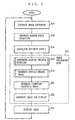
- FIG. 1 is a block diagram showing the hardware structure of a drive assistant system 100 according to the embodiment of the present invention.
- the drive assistant system 100 includes an input device 1, N (where N is a natural number equal to 1 or larger) cameras 2 1 to 2 N , a rudder angle sensor 3, a rendering device 10, and a display device 8.
- the rendering device 10 here includes ROM 4, RAM 5, and a CPU 6.
- the input device 1 is found in a position where a driver of the vehicle is easy to operate, and composed of a remote controller, a touch panel, an operation button, and the like.
- the cameras 2 1 to 2 N are fixedly placed in each different predetermined position in the vehicle, and have charge of capturing images of around the vehicle.
- the cameras 2 1 to 2 N are each assigned an identification value, and identified thereby.
- the identification values in this embodiment are the numerical subscripts accompanying the reference numeral 2 of the cameras.
- the rudder angle sensor 3 is also placed in a predetermined position in the vehicle, and detects the rudder angle of the steering wheel.
- the CPU 6 runs following a program in the ROM 4, and thereby functions as path calculating means and image processing means, and generates a display image (these expressions appear in Claims) .
- the RAM 5 is used as a working area for the CPU 6.
- a region hereinafter, referred to as a frame buffer
- frame memory is also reserved as a region wherein the display image is generated by the CPU 6.
- the ROM 4 stores data representing a three-dimensional model of the vehicle.
- the vehicle model is equivalent in size to the actual vehicle.
- the vehicle model may be somewhat bigger than the actual vehicle.
- the display device 8 is typically a liquid crystal display, and displays the display image generated by the CPU 6.
- Such structured system 100 is typically found useful by the driver when he/she moves the vehicle backward to park between other vehicles behind.
- the driver operates the input device 1.
- the input device 1 instructs the CPU 6 to execute the program.
- the CPU 6 then starts going through such procedure as shown in FIG. 2 in accordance with the program in the ROM 4.
- the CPU 6 needs any image of around the vehicle, specifically any image covering the area rear of the vehicle.
- the camera 2 i then responsively captures a frame of an image of around the vehicle, and then transfers the captured image to the RAM 5.
- the N cameras 2 1 to 2 N each receive such instruction, and transfer an image captured thereby to the frame buffer reserved therefor.
- the CPU 6 runs as follows concurrently with the cameras' image capturing.
- the CPU 6 instructs the rudder angle sensor 3 to detect to what degree the steering wheel is now turned (step S12).
- the rudder angle sensor 3 accordingly detects the current rudder angle of the steering wheel, and transmits the detected result to the CPU 6.
- the CPU 6 calculates an estimated path L , which is typically traced on a road surface for the vehicle to take (step S14).
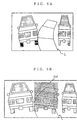
- the drive assistant system 100 displays in a display image a vehicle model fully placed on the estimated path L . This is aimed to help the driver easily figure out any possible bump against vehicles and other objects if he/she keeps moving his/her vehicle with the current rudder angle on the estimated path L .
- the vehicle model is displayed as if moving toward the parking space by degrees on the estimated path L (see FIG. 6).
- the vehicle model keeps moving by a predetermined quantity (hereinafter, referred to as a movement unit) .
- the movement quantity of the vehicle model reaches its predetermined maximum value, the vehicle model returns to its predetermined initial position.
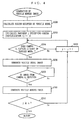
- the CPU 6 carries out image processing of step S15 after step S14 is through. In the image processing, the CPU 6 first goes through such calculation procedure as shown in FIG. 3 to determine where to display the vehicle model on the estimated path L in the display image (step S16). Such position is hereinafter referred to as a display vehicle position.
- a "display distance” denotes a distance (equivalent to a distance in the actual space) covered by the vehicle model on the estimated path L in the display image.
- the display distance is set to an initial distance first.
- the "initial distance” denotes a first display position of the vehicle model.
- the initial distance is typically set to an appropriate value as are the movement unit and the maximum distance during when the drive assistant system 100 is manufactured.
- the movement unit is exemplarily set to 0.5m, and the maximum distance to 3m. Those values are preferably resettable depending on the drivers' preferences.
- step S16 of FIG. 2 the CPU 6 starts going through the calculation procedure of FIG. 3.
- the CPU 6 fetches the initial distance if this step is through for the first time, and if not, fetched is the display distance previously calculated in the same step (step S100).
- fetched display distance is referred to as a previous display distance.
- the previous display distance is added with the movement unit, and the resulting value is the current display distance (step S102).
- the current display distance is determined whether or not exceeding the maximum value predetermined therefor (step S104). If exceeded, the current display distance is set to the initial distance (step S106), and then the procedure goes to step S108. If not yet exceeding, the procedure skips step S106, and goes to step S108.
- step S108 the estimated path L calculated in step S14 is partially picked up for the length equivalent to the current display distance from the current position of the vehicle model.
- a partial estimated path such picked-up part of the estimated path L is referred to as a partial estimated path.
- the display distance tells on which part of the estimated path L the vehicle model is now positioned (i.e., where the partial estimated path ends) , and there, to which direction the estimated path L is directed (step S110) (see FIG. 6) .
- position and direction of the vehicle model are equivalent to those in the actual space, and collectively referred to as vehicle information.
- the current display distance is stored in the RAM 5 to be prepared for step S110 in the next calculation procedure (step S112).
- step S112 the CPU 6 goes through such generation procedure as shown in FIG. 4 based on the vehicle information set in step S110 (step S18 in FIG. 2).
- An image generated thereby has the vehicle model overlaid thereon, and referred to as a vehicle merged image.
- the CPU 6 calculates a region to be occupied in the display image by the vehicle model, which is defined by position and direction according to the vehicle information set in step S110.
- the region is equivalent to a region in the actual space (step S200).
- the CPU 6 initializes to "1" a variable j specifying the identification values assigned to the cameras (step S202), and then sees if thus specified camera 2 j catches, presumably, a sight of the vehicle model occupying the region as calculated above (step S204). If determined No, the variable j is incremented by 1, and step S204 is repeated with the newly specified camera 2 j . If the determination thereby becomes Yes, the vehicle model viewed from the camera 2 j is generated as a vehicle model image (step S206).
- the CPU 6 waits for the image captured by the camera 2 j to receive (step S208).
- the frame buffer in the RAM 5 for the camera 2 i (hereinafter, referred to as a target frame buffer) stores the same image.
- the CPU 6 overlays the vehicle model image generated in step S206, and generates a frame of the vehicle merged image (step S210).
- the CPU 6 determines that the process of generating the vehicle overlaid image is now completed, and the procedure goes to step S20 in FIG. 2.
- the frame buffers in the RAM 5 respectively reserved for the cameras 2 1 to 2 N store either the vehicle overlaid image or the captured image.
- the CPU 6 performs viewpoint conversion processing on the above-described frame memory according to a predetermined mapping table (step S20).
- the resulting image generated thereby is a viewpoint converted image, which shows the area around the vehicle viewed from a predetermined virtual viewpoint.
- the virtual viewpoint is so selected as to make the resulting image viewed therefrom indicative enough for the driver to figure out in what state the area around the vehicle and the parking space is.
- the virtual viewpoint here is different from those for the cameras 2 1 to 2 N , and suitably selected to help the driver grasp the surrounding state between the vehicle and the parking space.
- the virtual viewpoint is set proximal to the roof of the vehicle or up higher.
- the viewpoint converted image includes the vehicle model image viewed from the virtual viewpoint.
- every pixel in each of the images in the frame buffers (vehicle overlaid image and captured image) is mapped to a road surface whereon the vehicle moves, and the road surface is viewed from the virtual viewpoint to generate an image.
- any object observed in the resulting viewpoint converted image is neglected with its height component, and resultantly looks deformed.
- the object includes other vehicle in a close range, the vehicle model itself, obstacle, and the like.
- the CPU 6 overlays the estimated path L calculated in step S14 onto the viewpoint converted image, and the display image is generated (step S22).
- the CPU 6 then transfers thus generated display image to the display device 8 for display thereon (step S24).
- the display image includes a vehicle model Imd located on the estimated path L .
- the vehicle model Imd moves backward on the estimated path L by the movement unit by repeating the processing in FIG. 2, and when the display distance reaches its predetermined value, returns to the initial distance.
- a display image shows a vehicle model on a path estimated for the vehicle together with an area rear of the vehicle.
- a driver of the vehicle can exactly aim at a parking space available for his/her vehicle on estimated path.
- the driver can precisely figure out if his/her vehicle can fit in the parking space.
- the vehicle model Imd is displayed as if moving backward on the estimated path L . Therefore, the driver can easily figure out only by seeing the display image whether or not the vehicle model Imd moving on the estimated path L hits any obstacle typified by other vehicle in a close range.
- any object observed therein looks deformed as its height component is neglected.
- the vehicle model even if any object such as other vehicle and obstacle appearing in the display image is deformed due to a merging map, the vehicle model also looks deformed. This is because, with the procedure of FIG. 4, a viewpoint converted image is generated based on a vehicle overlaid image which is generated by overlaying an image of the vehicle model viewed from the specified camera. As every object in the display image including the vehicle model itself is deformed, the driver can correctly figure out any possible bump against obstacles therearound. If the vehicle model is not deformed as other objects in the display image, the driver finds it difficult to measure an exact space between the vehicle model and the deformed obstacle.
- the display image shows the vehicle model for the purpose of helping the driver to park.
- an individual parking space is defined in a specific pattern (usually in a rectangular pattern) by white lines, for example. If so, the white lines are sufficient for the driver to recognize any available parking space, and thus the vehicle model is not considered essential in the display image, and only the estimated path will do.
- the CPU 6 may detect whether the specific pattern as above is observed in an area for where the vehicle is heading, and if detected, the vehicle model may not be displayed.
- the detection technique as such is well known in this field.
- step S210 of FIG. 4 may be skipped.
- the vehicle model may be set somewhat bigger than the actual vehicle.
- the vehicle is presumed to move backward to park.
- the assistant device of the present invention is surely applicable to a case where the vehicle moves forward to park.
- the program is stored in the ROM 5.
- the program may be distributed in a recording medium typified by CD-ROM, or over a communications network such as the Internet.
- the vehicle model may partially hide the area ahead or rear of the vehicle in the display image. Therefore, the vehicle model may be translucent or wire-framed. In this manner, the display image generated by the rendering device 10 has no blind spot, and the drive thus can check the area front or rear of the vehicle to a greater degree. Especially in the case that the vehicle model is wire-framed, computation load can be reduced compared with the case where the vehicle image is simply rendered.
Abstract
Description
Claims (10)
- A rendering device for generating a display image of around a vehicle for drive assistance, comprising:vehicle model storing means (4) for storing a vehicle model representing said vehicle;path calculating means (6) for calculating an estimated path for said vehicle based on a rudder angle of the vehicle provided by rudder angle detecting means placed in the vehicle;receiving means (6) for receiving a captured image of around said vehicle from image capturing means placed in the vehicle; andimage processing means (6) for generating the display image based on said captured image, said estimated path, and said vehicle model, whereinthe display image generated by said image processing means is displayed by display means placed in said vehicle, and includes said vehicle model arranged on said estimated path.
- The rendering device according to claim 1, wherein said vehicle model is a 3D model, andsaid image processing means comprises:vehicle position determining means (6) for determining a display position on said estimated path for said vehicle model;vehicle model image generating means (6) for generating a vehicle model image by viewing the vehicle model stored in said vehicle model storing means from a viewpoint of said image capturing means; andvehicle merged image generating means (6) for generating a vehicle merged image by overlaying said vehicle model image onto the captured image received by said receiving means, whereinsaid display image is generated based on said vehicle merged image.
- The rendering device according to claim 2, whereinsaid image capturing means includes a plurality of cameras for capturing an image of around said vehicle from each viewpoint, and generating the captured image,said image processing means further includes viewpoint converted image generating means (6) for generating a viewpoint converted image by viewing said vehicle and therearound from a predetermined virtual viewpoint,said vehicle merged image generating means generates the vehicle merged image based on the captured images received by said receiving means from said plurality of cameras,said viewpoint converted image generating means generates said viewpoint converted image based on the vehicle merged image generated by said vehicle merged image generating means, andsaid display image is generated based on said viewpoint converted image.
- The rendering device according to claim 3, wherein said image processing means further includes display image generating means (6) for generating the display image by overlaying said estimated path onto said viewpoint converted image.
- The rendering device according to claim 1, further comprising specific pattern determining means for determining whether there is a specific pattern indicating a parking space available for said vehicle, wherein
when said pattern determining means determines that there is said specific pattern, said image processing means generates the display image which does not include said vehicle model. - The rendering device according to claim 2, wherein said vehicle merged image generating means merges said vehicle model image which is translucent to the captured image received by said receiving means, and generates the vehicle merged image.
- The rendering device according to claim 2, wherein said vehicle merged image generating means merges said vehicle model image which is wire-framed to the captured image received by said receiving means, and generates the vehicle merged image.
- A rendering method for generating a display image of around a vehicle for drive assistance, wherein a vehicle model representing said vehicle is previously stored, andsaid method comprises the steps of:a path calculation step (S14) of calculating an estimated path for said vehicle based on a rudder angle of the vehicle provided by rudder angle detecting means placed in the vehicle;a reception step (S208) of receiving a captured image of around said vehicle from image capturing means placed in the vehicle; andan image processing step (S22) of generating the display image based on said captured image, said estimated path, and said vehicle model, whereinthe display image generated in said image processing step is displayed by display means placed in said vehicle, and includes said vehicle model arranged on said estimated path.
- A recording medium on which a program for generating a display image of around a vehicle for drive assistance is stored, wherein a vehicle model representing said vehicle is previously stored, andsaid program comprises the steps of:a path calculation step (S14) of calculating an estimated path for said vehicle based on a rudder angle of the vehicle provided by rudder angle detecting means placed in the vehicle;a reception step (S208) of receiving a captured image of around said vehicle from image capturing means placed in the vehicle; andan image processing step (S22) of generating the display image based on said captured image, said estimated path, and said vehicle model, whereinthe display image generated in said image processing step is displayed by display means placed in said vehicle, and includes said vehicle model arranged on said estimated path.
- A program for generating a display image of around a vehicle for drive assistance, wherein a vehicle model representing said vehicle is previously stored, andsaid program comprises the steps of:a path calculation step (S14) of calculating an estimated path for said vehicle based on a rudder angle of the vehicle provided by rudder angle detecting means placed in the vehicle;a reception step (S208) of receiving a captured image of around said vehicle from image capturing means placed in the vehicle; andan image processing step (S22) of generating the display image based on said captured image, said estimated path, and said vehicle model, whereinthe display image generated in said image processing step is displayed by display means placed in said vehicle, and includes said vehicle model arranged on said estimated path.
Applications Claiming Priority (2)
| Application Number | Priority Date | Filing Date | Title |
|---|---|---|---|
| JP2000199516 | 2000-06-30 | ||
| JP2000199516 | 2000-06-30 |
Publications (3)
| Publication Number | Publication Date |
|---|---|
| EP1167120A2 true EP1167120A2 (en) | 2002-01-02 |
| EP1167120A3 EP1167120A3 (en) | 2004-01-14 |
| EP1167120B1 EP1167120B1 (en) | 2014-08-27 |
Family
ID=18697518
Family Applications (1)
| Application Number | Title | Priority Date | Filing Date |
|---|---|---|---|
| EP01115330.1A Expired - Lifetime EP1167120B1 (en) | 2000-06-30 | 2001-06-25 | Rendering device for parking aid |
Country Status (2)
| Country | Link |
|---|---|
| US (1) | US6366221B1 (en) |
| EP (1) | EP1167120B1 (en) |
Cited By (4)
| Publication number | Priority date | Publication date | Assignee | Title |
|---|---|---|---|---|
| EP1288072A2 (en) * | 2001-08-28 | 2003-03-05 | Aisin Seiki Kabushiki Kaisha | Driver assistance device taking into account the overhang of other vehicles |
| EP1405776A1 (en) | 2002-09-30 | 2004-04-07 | Aisin Seiki Kabushiki Kaisha | Movable body circumstance monitoring apparatus |
| FR2929196A1 (en) * | 2008-03-31 | 2009-10-02 | Imra Europ Sas Soc Par Actions | Maneuver assistant for detecting and preventing collision to park e.g. automobile, has monitor or screen for displaying augmented reality image formed by superposition of image of ego-vehicle on selected anterior image |
| CN102211658A (en) * | 2010-04-09 | 2011-10-12 | 云南省航务管理局 | Digital pickup rudder angle acquisition and analysis system and method for processing data by using same |
Families Citing this family (24)
| Publication number | Priority date | Publication date | Assignee | Title |
|---|---|---|---|---|
| DE19925584A1 (en) * | 1999-06-04 | 2000-12-21 | Bosch Gmbh Robert | Route visualization method and device |
| JP3575364B2 (en) * | 1999-12-28 | 2004-10-13 | 株式会社豊田自動織機 | Steering support device |
| EP1158804A3 (en) * | 2000-05-24 | 2003-12-17 | Matsushita Electric Industrial Co., Ltd. | Rendering device for generating a display image |
| US6825779B2 (en) * | 2000-06-30 | 2004-11-30 | Matsushita Electric Industrial Co., Ltd. | Rendering device |
| EP1168248A3 (en) * | 2000-06-30 | 2003-12-10 | Matsushita Electric Industrial Co., Ltd. | Rendering device |
| US20030222982A1 (en) * | 2002-03-28 | 2003-12-04 | Hamdan Majil M. | Integrated video/data information system and method for application to commercial vehicles to enhance driver awareness |
| JP4094325B2 (en) * | 2002-04-05 | 2008-06-04 | 松下電器産業株式会社 | Parking driving support device |
| US20070035625A9 (en) * | 2002-12-20 | 2007-02-15 | Hamdan Majed M | Vehicle video processing system |
| JP3860552B2 (en) * | 2003-03-25 | 2006-12-20 | 富士通株式会社 | Imaging device |
| DE10317044A1 (en) * | 2003-04-11 | 2004-10-21 | Daimlerchrysler Ag | Optical monitoring system for use in maneuvering road vehicles provides virtual guide surfaces to ensure collision free movement |
| US20050093975A1 (en) * | 2003-10-30 | 2005-05-05 | Hamdan Majed M. | Adaptation of vision systems for commerical vehicles |
| WO2006136664A1 (en) | 2005-06-24 | 2006-12-28 | Renault Trucks | Drive assisting method for reversal path with a drawn vehicle |
| WO2007000502A1 (en) | 2005-06-24 | 2007-01-04 | Renault Trucks | Method for determining a set steering angle of steered wheels of a vehicle |
| US20100222964A1 (en) * | 2005-06-24 | 2010-09-02 | Renault Trucks | Method for Controlling the Steering Angle of the Vehicle Guiding Wheels |
| JP4762698B2 (en) * | 2005-11-30 | 2011-08-31 | アルパイン株式会社 | Vehicle peripheral image display device |
| US7737866B2 (en) * | 2007-09-27 | 2010-06-15 | Automotive Research & Testing Center | Auto-parking device |
| JP4412380B2 (en) * | 2007-10-02 | 2010-02-10 | アイシン・エィ・ダブリュ株式会社 | Driving support device, driving support method, and computer program |
| US8665116B2 (en) | 2010-07-18 | 2014-03-04 | Ford Global Technologies | Parking assist overlay with variable brightness intensity |
| US20120016555A1 (en) * | 2010-07-18 | 2012-01-19 | Maher Ghneim | Method and system for parking assist |
| DE102010048185B4 (en) * | 2010-10-13 | 2021-10-28 | Wirtgen Gmbh | Self-propelled construction machine |
| EP2581268B2 (en) * | 2011-10-13 | 2019-09-11 | Harman Becker Automotive Systems GmbH | Method of controlling an optical output device for displaying a vehicle surround view and vehicle surround view system |
| US9177404B2 (en) | 2012-10-31 | 2015-11-03 | Qualcomm Incorporated | Systems and methods of merging multiple maps for computer vision based tracking |
| KR102258628B1 (en) * | 2014-11-03 | 2021-06-02 | 현대모비스 주식회사 | Method for adjusting parking guide |
| JP6936098B2 (en) * | 2017-09-29 | 2021-09-15 | トヨタ自動車株式会社 | Object estimation device |
Citations (4)
| Publication number | Priority date | Publication date | Assignee | Title |
|---|---|---|---|---|
| EP0835796A2 (en) * | 1996-10-09 | 1998-04-15 | Honda Giken Kogyo Kabushiki Kaisha | Automatic steering system for verhicle |
| EP0841648A2 (en) * | 1992-09-30 | 1998-05-13 | Hitachi, Ltd. | Vehicle driving support system and vehicle therewith |
| GB2320326A (en) * | 1996-12-12 | 1998-06-17 | Samsung Electronics Co Ltd | Collision warning by path prediction of a vehicle |
| DE19741896A1 (en) * | 1997-09-23 | 1999-04-22 | Opel Adam Ag | Automobile image screen display for potentially hazardous situations, e.g. traffic accidents during parking |
Family Cites Families (11)
| Publication number | Priority date | Publication date | Assignee | Title |
|---|---|---|---|---|
| JPS6414700A (en) | 1987-07-08 | 1989-01-18 | Aisin Aw Co | Device for displaying prospective track of vehicle |
| US5670935A (en) * | 1993-02-26 | 1997-09-23 | Donnelly Corporation | Rearview vision system for vehicle including panoramic view |
| JPH07195978A (en) | 1993-12-30 | 1995-08-01 | Nissan Motor Co Ltd | Vehicle surroundings display unit |
| JP3431678B2 (en) | 1994-02-14 | 2003-07-28 | 三菱自動車工業株式会社 | Ambient situation display device for vehicles |
| JP3475507B2 (en) | 1994-08-08 | 2003-12-08 | 日産自動車株式会社 | Ambient monitoring device for vehicles |
| US5742141A (en) * | 1996-06-04 | 1998-04-21 | Ford Motor Company | Semi-autonomous parking control system for a vehicle providing tactile feedback to a vehicle operator |
| JPH10117340A (en) | 1996-10-11 | 1998-05-06 | Yazaki Corp | Vehicle periphery monitoring device, alarm display method to be used for device and medium-storing display method |
| JP3044534B2 (en) * | 1997-04-28 | 2000-05-22 | 本田技研工業株式会社 | Automatic vehicle steering system |
| JP3311274B2 (en) * | 1997-08-29 | 2002-08-05 | 本田技研工業株式会社 | Automatic vehicle steering system |
| JPH1178692A (en) | 1997-09-03 | 1999-03-23 | Nissan Motor Co Ltd | Image display device for vehicle |
| JP2000161915A (en) * | 1998-11-26 | 2000-06-16 | Matsushita Electric Ind Co Ltd | On-vehicle single-camera stereoscopic vision system |
-
2001
- 2001-06-25 EP EP01115330.1A patent/EP1167120B1/en not_active Expired - Lifetime
- 2001-06-28 US US09/892,744 patent/US6366221B1/en not_active Expired - Lifetime
Patent Citations (4)
| Publication number | Priority date | Publication date | Assignee | Title |
|---|---|---|---|---|
| EP0841648A2 (en) * | 1992-09-30 | 1998-05-13 | Hitachi, Ltd. | Vehicle driving support system and vehicle therewith |
| EP0835796A2 (en) * | 1996-10-09 | 1998-04-15 | Honda Giken Kogyo Kabushiki Kaisha | Automatic steering system for verhicle |
| GB2320326A (en) * | 1996-12-12 | 1998-06-17 | Samsung Electronics Co Ltd | Collision warning by path prediction of a vehicle |
| DE19741896A1 (en) * | 1997-09-23 | 1999-04-22 | Opel Adam Ag | Automobile image screen display for potentially hazardous situations, e.g. traffic accidents during parking |
Cited By (6)
| Publication number | Priority date | Publication date | Assignee | Title |
|---|---|---|---|---|
| EP1288072A2 (en) * | 2001-08-28 | 2003-03-05 | Aisin Seiki Kabushiki Kaisha | Driver assistance device taking into account the overhang of other vehicles |
| EP1288072A3 (en) * | 2001-08-28 | 2004-02-04 | Aisin Seiki Kabushiki Kaisha | Driver assistance device taking into account the overhang of other vehicles |
| EP1405776A1 (en) | 2002-09-30 | 2004-04-07 | Aisin Seiki Kabushiki Kaisha | Movable body circumstance monitoring apparatus |
| FR2929196A1 (en) * | 2008-03-31 | 2009-10-02 | Imra Europ Sas Soc Par Actions | Maneuver assistant for detecting and preventing collision to park e.g. automobile, has monitor or screen for displaying augmented reality image formed by superposition of image of ego-vehicle on selected anterior image |
| CN102211658A (en) * | 2010-04-09 | 2011-10-12 | 云南省航务管理局 | Digital pickup rudder angle acquisition and analysis system and method for processing data by using same |
| CN102211658B (en) * | 2010-04-09 | 2015-11-25 | 云南省航务管理局 | The method of data processing is carried out with digital camera rudder angle acquisition analysis system |
Also Published As
| Publication number | Publication date |
|---|---|
| US6366221B1 (en) | 2002-04-02 |
| EP1167120A3 (en) | 2004-01-14 |
| EP1167120B1 (en) | 2014-08-27 |
Similar Documents
| Publication | Publication Date | Title |
|---|---|---|
| US6366221B1 (en) | Rendering device | |
| US6483429B1 (en) | Parking assistance system | |
| JP4970926B2 (en) | Vehicle periphery monitoring device | |
| JP3494434B2 (en) | Parking assistance device | |
| JP3945467B2 (en) | Vehicle retraction support apparatus and method | |
| US9418556B2 (en) | Apparatus and method for displaying a blind spot | |
| US20030060972A1 (en) | Drive assist device | |
| KR102490272B1 (en) | A method for displaying the surrounding area of a vehicle | |
| EP1005234A2 (en) | Three-dimensional scope system for vehicles with a single camera | |
| US20140118551A1 (en) | Vehicle surrounding-area monitoring apparatus | |
| US20070147664A1 (en) | Driving assist method and driving assist apparatus | |
| EP2631696B1 (en) | Image generator | |
| JP2010136289A (en) | Device and method for supporting drive | |
| US20060171563A1 (en) | Vehicle-mounted image processor | |
| JP2013154730A (en) | Apparatus and method for processing image, and parking support system | |
| JP4797877B2 (en) | VEHICLE VIDEO DISPLAY DEVICE AND VEHICLE AROUND VIDEO DISPLAY METHOD | |
| US10733464B2 (en) | Method, system and device of obtaining 3D-information of objects | |
| US6999602B2 (en) | Image generation for assistance of drivers of vehicles | |
| JP2002104117A (en) | Driving support system for vehicle | |
| EP3761262A1 (en) | Image processing device and image processing method | |
| JP2000293693A (en) | Obstacle detecting method and device | |
| JP6375633B2 (en) | Vehicle periphery image display device and vehicle periphery image display method | |
| JP4493885B2 (en) | Driving support system | |
| JP4742695B2 (en) | Gaze recognition apparatus and gaze recognition method | |
| JP4661578B2 (en) | Mobile object recognition device |
Legal Events
| Date | Code | Title | Description |
|---|---|---|---|
| PUAI | Public reference made under article 153(3) epc to a published international application that has entered the european phase |
Free format text: ORIGINAL CODE: 0009012 |
|
| AK | Designated contracting states |
Kind code of ref document: A2 Designated state(s): AT BE CH CY DE DK ES FI FR GB GR IE IT LI LU MC NL PT SE TR |
|
| AX | Request for extension of the european patent |
Free format text: AL;LT;LV;MK;RO;SI |
|
| PUAL | Search report despatched |
Free format text: ORIGINAL CODE: 0009013 |
|
| AK | Designated contracting states |
Kind code of ref document: A3 Designated state(s): AT BE CH CY DE DK ES FI FR GB GR IE IT LI LU MC NL PT SE TR |
|
| AX | Request for extension of the european patent |
Extension state: AL LT LV MK RO SI |
|
| RIC1 | Information provided on ipc code assigned before grant |
Ipc: 7G 06T 1/00 B Ipc: 7B 60Q 1/48 A |
|
| 17P | Request for examination filed |
Effective date: 20040510 |
|
| AKX | Designation fees paid |
Designated state(s): DE FR GB |
|
| 17Q | First examination report despatched |
Effective date: 20080919 |
|
| RAP1 | Party data changed (applicant data changed or rights of an application transferred) |
Owner name: PANASONIC CORPORATION |
|
| GRAP | Despatch of communication of intention to grant a patent |
Free format text: ORIGINAL CODE: EPIDOSNIGR1 |
|
| INTG | Intention to grant announced |
Effective date: 20140620 |
|
| GRAS | Grant fee paid |
Free format text: ORIGINAL CODE: EPIDOSNIGR3 |
|
| GRAA | (expected) grant |
Free format text: ORIGINAL CODE: 0009210 |
|
| AK | Designated contracting states |
Kind code of ref document: B1 Designated state(s): DE FR GB |
|
| REG | Reference to a national code |
Ref country code: GB Ref legal event code: FG4D |
|
| REG | Reference to a national code |
Ref country code: DE Ref legal event code: R096 Ref document number: 60148974 Country of ref document: DE Effective date: 20141009 |
|
| REG | Reference to a national code |
Ref country code: DE Ref legal event code: R097 Ref document number: 60148974 Country of ref document: DE |
|
| PLBE | No opposition filed within time limit |
Free format text: ORIGINAL CODE: 0009261 |
|
| STAA | Information on the status of an ep patent application or granted ep patent |
Free format text: STATUS: NO OPPOSITION FILED WITHIN TIME LIMIT |
|
| 26N | No opposition filed |
Effective date: 20150528 |
|
| REG | Reference to a national code |
Ref country code: FR Ref legal event code: ST Effective date: 20160229 |
|
| PG25 | Lapsed in a contracting state [announced via postgrant information from national office to epo] |
Ref country code: FR Free format text: LAPSE BECAUSE OF NON-PAYMENT OF DUE FEES Effective date: 20150630 |
|
| PGFP | Annual fee paid to national office [announced via postgrant information from national office to epo] |
Ref country code: GB Payment date: 20160621 Year of fee payment: 16 |
|
| GBPC | Gb: european patent ceased through non-payment of renewal fee |
Effective date: 20170625 |
|
| PG25 | Lapsed in a contracting state [announced via postgrant information from national office to epo] |
Ref country code: GB Free format text: LAPSE BECAUSE OF NON-PAYMENT OF DUE FEES Effective date: 20170625 |
|
| REG | Reference to a national code |
Ref country code: DE Ref legal event code: R084 Ref document number: 60148974 Country of ref document: DE |
|
| PGFP | Annual fee paid to national office [announced via postgrant information from national office to epo] |
Ref country code: DE Payment date: 20200618 Year of fee payment: 20 |
|
| REG | Reference to a national code |
Ref country code: DE Ref legal event code: R071 Ref document number: 60148974 Country of ref document: DE |