JP4970926B2 - Vehicle periphery monitoring device - Google Patents
Vehicle periphery monitoring device Download PDFInfo
- Publication number
- JP4970926B2 JP4970926B2 JP2006349746A JP2006349746A JP4970926B2 JP 4970926 B2 JP4970926 B2 JP 4970926B2 JP 2006349746 A JP2006349746 A JP 2006349746A JP 2006349746 A JP2006349746 A JP 2006349746A JP 4970926 B2 JP4970926 B2 JP 4970926B2
- Authority
- JP
- Japan
- Prior art keywords
- vehicle
- monitoring object
- image
- image portion
- imaging
- Prior art date
- Legal status (The legal status is an assumption and is not a legal conclusion. Google has not performed a legal analysis and makes no representation as to the accuracy of the status listed.)
- Active
Links
- 238000012806 monitoring device Methods 0.000 title claims description 11
- 238000012544 monitoring process Methods 0.000 claims description 169
- 230000008859 change Effects 0.000 claims description 109
- 238000003384 imaging method Methods 0.000 claims description 83
- 238000000605 extraction Methods 0.000 claims description 17
- 238000000034 method Methods 0.000 description 34
- 230000008569 process Effects 0.000 description 24
- 238000012545 processing Methods 0.000 description 24
- 230000014509 gene expression Effects 0.000 description 10
- 238000010586 diagram Methods 0.000 description 7
- 238000013459 approach Methods 0.000 description 3
- 239000000284 extract Substances 0.000 description 3
- 230000009466 transformation Effects 0.000 description 3
- 238000012937 correction Methods 0.000 description 2
- 238000001514 detection method Methods 0.000 description 2
- 241001465754 Metazoa Species 0.000 description 1
- 238000006243 chemical reaction Methods 0.000 description 1
- 230000005484 gravity Effects 0.000 description 1
- 230000006872 improvement Effects 0.000 description 1
- 238000009434 installation Methods 0.000 description 1
- 230000016507 interphase Effects 0.000 description 1
- 238000002372 labelling Methods 0.000 description 1
- 230000003287 optical effect Effects 0.000 description 1
- 230000007704 transition Effects 0.000 description 1
Images


Classifications
-
- B—PERFORMING OPERATIONS; TRANSPORTING
- B60—VEHICLES IN GENERAL
- B60W—CONJOINT CONTROL OF VEHICLE SUB-UNITS OF DIFFERENT TYPE OR DIFFERENT FUNCTION; CONTROL SYSTEMS SPECIALLY ADAPTED FOR HYBRID VEHICLES; ROAD VEHICLE DRIVE CONTROL SYSTEMS FOR PURPOSES NOT RELATED TO THE CONTROL OF A PARTICULAR SUB-UNIT
- B60W50/00—Details of control systems for road vehicle drive control not related to the control of a particular sub-unit, e.g. process diagnostic or vehicle driver interfaces
- B60W50/08—Interaction between the driver and the control system
- B60W50/14—Means for informing the driver, warning the driver or prompting a driver intervention
-
- G—PHYSICS
- G06—COMPUTING; CALCULATING OR COUNTING
- G06F—ELECTRIC DIGITAL DATA PROCESSING
- G06F18/00—Pattern recognition
- G06F18/20—Analysing
- G06F18/25—Fusion techniques
- G06F18/251—Fusion techniques of input or preprocessed data
-
- G—PHYSICS
- G06—COMPUTING; CALCULATING OR COUNTING
- G06V—IMAGE OR VIDEO RECOGNITION OR UNDERSTANDING
- G06V10/00—Arrangements for image or video recognition or understanding
- G06V10/70—Arrangements for image or video recognition or understanding using pattern recognition or machine learning
- G06V10/77—Processing image or video features in feature spaces; using data integration or data reduction, e.g. principal component analysis [PCA] or independent component analysis [ICA] or self-organising maps [SOM]; Blind source separation
- G06V10/80—Fusion, i.e. combining data from various sources at the sensor level, preprocessing level, feature extraction level or classification level
- G06V10/803—Fusion, i.e. combining data from various sources at the sensor level, preprocessing level, feature extraction level or classification level of input or preprocessed data
-
- G—PHYSICS
- G06—COMPUTING; CALCULATING OR COUNTING
- G06V—IMAGE OR VIDEO RECOGNITION OR UNDERSTANDING
- G06V20/00—Scenes; Scene-specific elements
- G06V20/50—Context or environment of the image
- G06V20/56—Context or environment of the image exterior to a vehicle by using sensors mounted on the vehicle
- G06V20/58—Recognition of moving objects or obstacles, e.g. vehicles or pedestrians; Recognition of traffic objects, e.g. traffic signs, traffic lights or roads
-
- B—PERFORMING OPERATIONS; TRANSPORTING
- B60—VEHICLES IN GENERAL
- B60W—CONJOINT CONTROL OF VEHICLE SUB-UNITS OF DIFFERENT TYPE OR DIFFERENT FUNCTION; CONTROL SYSTEMS SPECIALLY ADAPTED FOR HYBRID VEHICLES; ROAD VEHICLE DRIVE CONTROL SYSTEMS FOR PURPOSES NOT RELATED TO THE CONTROL OF A PARTICULAR SUB-UNIT
- B60W2420/00—Indexing codes relating to the type of sensors based on the principle of their operation
- B60W2420/40—Photo or light sensitive means, e.g. infrared sensors
- B60W2420/403—Image sensing, e.g. optical camera
Landscapes
- Engineering & Computer Science (AREA)
- Theoretical Computer Science (AREA)
- Computer Vision & Pattern Recognition (AREA)
- General Physics & Mathematics (AREA)
- Physics & Mathematics (AREA)
- Automation & Control Theory (AREA)
- Artificial Intelligence (AREA)
- Data Mining & Analysis (AREA)
- Multimedia (AREA)
- Evolutionary Computation (AREA)
- General Health & Medical Sciences (AREA)
- General Engineering & Computer Science (AREA)
- Medical Informatics (AREA)
- Databases & Information Systems (AREA)
- Computing Systems (AREA)
- Life Sciences & Earth Sciences (AREA)
- Bioinformatics & Cheminformatics (AREA)
- Bioinformatics & Computational Biology (AREA)
- Evolutionary Biology (AREA)
- Software Systems (AREA)
- Health & Medical Sciences (AREA)
- Human Computer Interaction (AREA)
- Transportation (AREA)
- Mechanical Engineering (AREA)
- Traffic Control Systems (AREA)
- Image Analysis (AREA)
- Image Processing (AREA)
- Fittings On The Vehicle Exterior For Carrying Loads, And Devices For Holding Or Mounting Articles (AREA)
- Studio Devices (AREA)
Description
本発明は、車両に搭載された撮像手段により得られる画像から、車両周辺に所在する監視対象物を検出して、車両周辺を監視する車両周辺監視装置に関する。 The present invention relates to a vehicle periphery monitoring device that detects a monitoring target located around a vehicle from an image obtained by an imaging unit mounted on the vehicle and monitors the periphery of the vehicle.
従来より、車両に2台のカメラを搭載し、各カメラにより撮像された車両周囲の画像から抽出された同一の監視対象物の画像部分のずれ(視差)に基づいて、三角測量の原理により監視対象物と車両との距離を検出するようにした車両周辺監視装置が提案されている(例えば、特許文献1参照)。 Conventionally, two cameras are mounted on the vehicle, and monitoring is performed based on the principle of triangulation based on the deviation (parallax) of the image portion of the same monitoring object extracted from the image around the vehicle imaged by each camera. There has been proposed a vehicle periphery monitoring device that detects the distance between an object and a vehicle (see, for example, Patent Document 1).
かかる従来の車両周辺監視装置によれば、車両周辺の監視対象物と車両との距離を算出して、該距離により監視対象物の位置の画像座標から実空間座標への変換処理を行い、実空間における監視対象物の移動ベクトルを求めて、監視対象物と車両の接触可能性を判定している。 According to such a conventional vehicle periphery monitoring device, the distance between the monitoring object around the vehicle and the vehicle is calculated, and the conversion processing from the image coordinates of the position of the monitoring object to the real space coordinates is performed based on the distance. The movement vector of the monitoring object in the space is obtained, and the possibility of contact between the monitoring object and the vehicle is determined.
しかし、このように視差に基づいて監視対象物との距離を検出する場合には、2台のカメラを備えることによるコストアップを伴うと共に、両カメラの光軸調節を厳密に行わなければならない等の面倒な設置作業が必要となるという不都合があった。
本発明は上記不都合を解消し、車両に単一の撮像手段を備えた簡易な構成により、車両周辺の監視対象物と車両の接触可能性を判定することができる車両周辺監視装置を提供することを目的とする。 The present invention provides a vehicle periphery monitoring device that can solve the above inconveniences and can determine the possibility of contact between an object to be monitored around the vehicle and the vehicle with a simple configuration provided with a single imaging means in the vehicle. With the goal.
本発明は上記目的を達成するためになされたものであり、車両に搭載された単一の撮像手段により撮像された画像から、該車両周辺の監視対象物を検出する車両周辺監視装置の改良に関する。 The present invention has been made to achieve the above object, and relates to an improvement in a vehicle periphery monitoring device that detects a monitoring object around the vehicle from an image captured by a single imaging means mounted on the vehicle. .
そして、本発明は、前記撮像手段により撮像された画像から、監視対象物の画像部分を抽出する監視対象物抽出手段と、所定時間間隔をもって前記撮像手段により撮像された複数の画像から、前記監視対象物抽出手段により抽出された同一の監視対象物の画像部分の大きさの変化率を算出する変化率算出手段と、前記所定時間間隔をもって前記撮像手段により撮像された複数の画像から、前記監視対象物抽出手段により抽出された同一の監視対象物の画像部分の位置変化量を算出する位置変化量算出手段と、所定時点から前記所定時間間隔をもって前記撮像手段により撮像された複数の画像から、前記監視対象物抽出手段により抽出された同一の監視対象物の画像部分について、前記変化率算出手段により算出された該画像部分の大きさの変化率が該画像部分の拡大を示すものであり、且つ、前記位置変化量算出手段により算出された該画像部分の位置変化量が所定の位置変化閾値以下であるときに、監視対象物と前記車両との接触可能性が高いと判断する接触判定手段とを備え、前記監視対象物抽出手段は、前記撮像手段により撮像された画像から抽出する監視対象物の画像部分を、該撮像された画像を各画素の輝度に応じて2値化処理して生成した2値画像から抽出したものとし、前記変化率算出手段は、画像部分が同一の監視対象物の画像部分であることを、画像部分の面積の変化率に基づいて判定するとともに、前記大きさの変化率として画像部分の面積の変化率を用いることを特徴とする。
Then, the present invention provides a monitoring object extraction unit that extracts an image portion of the monitoring object from an image captured by the imaging unit, and a plurality of images captured by the imaging unit at a predetermined time interval. From the change rate calculation means for calculating the change rate of the size of the image portion of the same monitoring object extracted by the object extraction means, and the plurality of images taken by the imaging means at the predetermined time interval, the monitoring From the position change amount calculating means for calculating the position change amount of the image portion of the same monitoring object extracted by the object extracting means, and a plurality of images taken by the imaging means at a predetermined time interval from a predetermined time point, For the image portion of the same monitoring object extracted by the monitoring object extraction means, the change in the size of the image portion calculated by the change rate calculation means. When the rate indicates the enlargement of the image portion and the position change amount of the image portion calculated by the position change amount calculation means is equal to or less than a predetermined position change threshold, the monitoring object and the vehicle A contact determination unit that determines that there is a high possibility of contact with the monitoring object, and the monitoring object extraction unit extracts an image portion of the monitoring object to be extracted from the image captured by the imaging unit. It is assumed that the image is extracted from a binary image generated by binarization processing according to the luminance of each pixel, and the change rate calculation means determines that the image portion is an image portion of the same monitoring object. A determination is made based on a change rate of the area, and a change rate of the area of the image portion is used as the change rate of the size .
かかる本発明によれば、前記所定時間間隔をもって車両周辺の監視対象物を複数回撮像した場合、各回の撮像画像における該監視対象物の画像部分の大きさの変化は、該監視対象物と車両との相対速度が高いほど大きくなる。そのため、前記接触判定手段は、前記変化率算出手段により算出された同一の監視対象物の画像部分の大きさの変化率から、監視対象物と車両間の相対的な位置の変化を推定して、監視対象物と車両の接触可能性を判断することができる。そして、本発明によれば、このように、単一の撮像手段による撮像画像から監視対象物と車両との接触可能性を判断することできるため、2台の撮像手段を用いる場合に比べて装置のコストダウンを図ることができ、また、車両への撮像手段の取付を容易なものとすることができる。 According to the present invention, when the monitoring object around the vehicle is imaged a plurality of times at the predetermined time interval, the change in the size of the image portion of the monitoring object in each captured image is different between the monitoring object and the vehicle. The higher the relative speed, the larger. Therefore, the contact determination means estimates a change in the relative position between the monitoring object and the vehicle from the change rate of the size of the image portion of the same monitoring object calculated by the change rate calculation means. The possibility of contact between the monitoring object and the vehicle can be determined. Thus, according to the present invention, since the possibility of contact between the monitoring object and the vehicle can be determined from the image captured by the single imaging unit, the apparatus is compared with the case where two imaging units are used. The cost can be reduced, and the attachment of the imaging means to the vehicle can be facilitated.
さらに、本発明によれば、前記所定時点から前記所定時間間隔をもって前記撮像手段により撮像された複数の画像から、前記監視対象物抽出手段により抽出された監視対象物の画像部分について、前記変化率算出手段により算出された該画像部分の大きさの変化率が該画像部分の拡大を示すものであるときは、前記車両と該監視対象物が近付いて、前記車両と該監視対象物間の距離が短くなっていると判断することができる。そして、前記位置変化量算出手段により算出された前記位置変化量が前記閾値以下であるときには、前記車両に向かって監視対象物が近付いていると判断することができる。そのため、この場合に、前記接触判定手段は、監視対象物と車両との接触可能性が高いと判定することができる。 Furthermore, according to the present invention, the rate of change of the image portion of the monitoring object extracted by the monitoring object extraction unit from the plurality of images captured by the imaging unit at the predetermined time interval from the predetermined time point. When the rate of change of the size of the image portion calculated by the calculation means indicates the enlargement of the image portion, the vehicle and the monitoring object come close to each other, and the distance between the vehicle and the monitoring object Can be determined to be shorter. And it is, when the position change amount calculated by the pre-Symbol position change amount calculating means is equal to or less than the threshold value, it can be determined that the monitored object toward the vehicle is approaching. Therefore, in this case, the contact determination unit can determine that the possibility of contact between the monitoring object and the vehicle is high.
また、前記変化率に基づいて、監視対象物が前記車両に到達するまでの時間である自車両到達時間を推定する到達時間推定手段を備え、前記接触判定手段は、所定時点から前記所定時間間隔をもって前記撮像手段により撮像された複数の画像から、前記監視対象物抽出手段により抽出された同一の監視対象物の画像部分について、前記変化率算出手段により算出された該画像部分の大きさの変化率が該画像部分の拡大を示すものであり、且つ、前記位置変化量算出手段により算出された該画像部分の位置変化量が所定の位置変化閾値以下であり、且つ、前記到達時間推定手段により推定された前記自車両到達時間が所定時間以下であるときに、監視対象物と前記車両との接触可能性が高いと判断することを特徴とする。 In addition, it includes arrival time estimation means for estimating a host vehicle arrival time, which is a time until the monitoring target reaches the vehicle, based on the rate of change, and the contact determination means includes a predetermined time interval from a predetermined time point. For the image portion of the same monitoring object extracted by the monitoring object extraction means from the plurality of images taken by the imaging means, the change in the size of the image portion calculated by the change rate calculation means The rate indicates the enlargement of the image portion, the position change amount of the image portion calculated by the position change amount calculation means is less than or equal to a predetermined position change threshold, and the arrival time estimation means When the estimated arrival time of the host vehicle is equal to or shorter than a predetermined time, it is determined that the possibility of contact between the monitored object and the vehicle is high.
かかる本発明によれば、前記接触判定手段は、前記自車両到達時間が前記所定時間以下であり、前記車両と監視対象物との接触までの緊急性が高い場合に限定して、監視対象物と前記車両との接触可能性が高いと判断することができる。 According to the present invention, the contact determination means is limited to a case where the own vehicle arrival time is equal to or shorter than the predetermined time and the urgency to contact between the vehicle and the monitoring object is high. It can be determined that the possibility of contact with the vehicle is high.
また、前記車両と監視対象物間の距離を検出する測距手段と、前記車両と監視対象物間の距離に応じて、前記閾値を設定する閾値設定手段とを備えたことを特徴とする。 Further, it is characterized by comprising distance measuring means for detecting a distance between the vehicle and the monitoring object, and threshold setting means for setting the threshold according to the distance between the vehicle and the monitoring object.
かかる本発明によれば、前記車両と監視対象物間の距離が短くなるほど、実空間上での監視対象物の位置の変化に対する画像上での該監視対象物の画像部分の位置の変化が大きくなる。そのため、前記閾値設定手段により、前記車両と監視対象物間の距離に応じて前記位置変化閾値を設定することによって、接触可能性判断の精度を高めることができる。 According to the present invention, the shorter the distance between the vehicle and the monitoring object, the greater the change in the position of the image portion of the monitoring object on the image relative to the change in the position of the monitoring object in real space. Become. Therefore, by setting the position change threshold according to the distance between the vehicle and the monitoring object by the threshold setting means, it is possible to improve the accuracy of the contact possibility determination.
また、前記位置変化閾値設定手段は、前記所定時点から前記所定間隔をもって前記撮像手段により監視対象物が撮像されたときに、前記測距手段により検出した各撮像時における前記車両と監視対象物間の距離と、前記車両の車幅又は車高と、前記撮像手段の焦点距離とに基づいて、前記位置変化閾値を設定することを特徴とする。 Further, the position change threshold value setting means is configured such that when the monitoring object is imaged by the imaging means at the predetermined interval from the predetermined time point, the distance between the vehicle and the monitoring object at each imaging time detected by the distance measuring means The position change threshold is set based on the distance, the vehicle width or height of the vehicle, and the focal length of the imaging means.
かかる本発明によれば、詳細は後述するが、前記測距手段により検出した各撮像時における前記車両と監視対象物間の距離と、前記車両の車幅又は車高と、前記撮像手段の焦点距離とに基づいて、監視対象物の実空間上の移動状況と前記車両の大きさを反映した前記位置変化閾値を設定することができる。 According to the present invention, as will be described in detail later, the distance between the vehicle and the monitoring object at the time of imaging detected by the distance measuring means, the vehicle width or height of the vehicle, and the focus of the imaging means. Based on the distance, it is possible to set the position change threshold value reflecting the movement state of the monitoring object in the real space and the size of the vehicle.
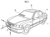
本発明の実施の形態の一例について、図1〜図10を参照して説明する。図1は本発明の車両周囲監視装置の構成図、図2は図1に示した車両周囲監視装置の車両への取り付け態様の説明図、図3は監視対象物の画像部分の大きさの変化を示した説明図、図4は図1に示した画像処理ユニットの第2の実施の形態における処理手順を示したフローチャート、図5は監視対象物の時間間追跡の説明図、図6は実空間における監視対象物の移動ベクトルの推定処理の説明図、図7は監視対象物の画像の大きさの変化率を画像間の相間演算により算出する方法の説明図、図8は図1に示した画像処理ユニットの第3の実施の形態における処理手順を示したフローチャート、図9は位置変化量を用いた接触判別処理の説明図、図10は位置変化閾値の設定処理の説明図である。 An example of an embodiment of the present invention will be described with reference to FIGS. FIG. 1 is a configuration diagram of a vehicle surroundings monitoring apparatus according to the present invention, FIG. 2 is an explanatory view of an attachment mode of the vehicle surroundings monitoring apparatus shown in FIG. 1 to a vehicle, and FIG. FIG. 4 is a flowchart showing a processing procedure in the second embodiment of the image processing unit shown in FIG. 1, FIG. 5 is an explanatory diagram of time tracking of the monitoring object, and FIG. FIG. 7 is an explanatory diagram of a method for estimating the movement vector of the monitoring object in the space, FIG. 7 is an explanatory diagram of a method for calculating the rate of change in the size of the image of the monitoring object by the inter-image calculation, and FIG. 9 is a flowchart showing a processing procedure in the third embodiment of the image processing unit, FIG. 9 is an explanatory diagram of a contact determination process using a position change amount, and FIG. 10 is an explanatory diagram of a position change threshold value setting process.
図1を参照して、本発明の車両周囲監視装置は、画像処理ユニット1と、遠赤外線を検出可能な赤外線カメラ2(本発明の撮像手段に相当する)と、車両のヨーレートを検出するヨーレートセンサ3と、車両の走行速度を検出する車速センサ4と、運転者によるブレーキの操作量を検出するブレーキセンサ5と、赤外線カメラ2により得られる画像から車両前方の監視対象物(動物等)を検出し、該監視対象物と車両が接触する可能性が高い場合に警報を出力する画像処理ユニット1と、音声により警報を行うためのスピーカ6と、赤外線カメラ2により得られた画像を表示すると共に、接触の可能性が高い監視対象物を運転者に視認させる表示を行うためのヘッドアップディスプレイ(以下、HUDという)7とを備えている。
Referring to FIG. 1, a vehicle surrounding monitoring apparatus according to the present invention includes an
図2を参照して、赤外線カメラ2は、車両10の前部に配置され、撮像物の温度が高い程出力レベルが高くなる(輝度が大きくなる)特性を有している。また、HUD7は、車両10のフロントウィンドウの運転者側の前方位置に画面7aが表示されるように設けられている。
Referring to FIG. 2, the
また、画像処理ユニット1は、赤外線カメラ2から出力されるアナログの映像信号をデジタルデータに変換して画像メモリに取り込み、該画像メモリに取り込んだ車両前方の画像に対して各種演算処理を行う機能を有し、図1を参照して、該画像から監視対象物の画像部分を抽出する監視対象物抽出手段20、所定時間間隔をもって撮像された画像間における同一の監視対象物の画像部分の大きさの変化率Rateを算出する変化率算出手段21、該変化率Rateを用いて監視対象物が車両10に到達するまでの時間(本発明の自車両到達時間に相当する)Tを推定する到達時間推定手段22、監視対象物の実空間における位置を算出する実空間位置算出手段23、監視対象物の実空間における移動ベクトルを算出する移動ベクトル算出手段24、該移動ベクトルに基づいて監視対象物と車両10との接触可能性を判定する接触判定手段25、所定時間間隔をもって撮像された画像間における同一の監視対象物の画像部分の位置変化量Δx,Δyを算出する位置変化量算出手段26、及び位置変化量Δx,Δyから接触の可能性を判別するための位置変化閾値Thx,Thyを設定する位置変化閾値設定手段27を備えている。
The
[第1の実施の形態]本発明の第1の実施の形態における画像処理ユニット1による監視対象物が自車両10に到達するまでの時間の推定方法について、図3を参照して説明する。図3中、Im1は撮像時点t11における赤外線カメラ2の撮像画像であり、Im2は該時点t11からdT(本発明の所定時間間隔に相当する)経過した時点t10における赤外線カメラ2の撮像画像である。
[First Embodiment] A method of estimating the time until the monitoring object reaches the
Im1においては監視対象物として歩行者の画像部分31が撮像されており、Im2においては同一の歩行者の画像部分30が撮像されている。図3は歩行者が車両10に向かって歩いてきている状況を示しており、Im1の撮像時点t11よりもIm2の撮像時点t10の方が、歩行者が車両に接近しているため、Im1における歩行者の画像部分31の幅w11よりもIm2における歩行者の画像部分30の幅w10の方が、大きくなっている。
In Im1, a
この場合、変化率Rateと監視対象物が車両10に到達するまでの時間Tは、以下の式(1)の関係にある。そのため、到達時間推定手段22は、以下の式(2)により、変化率Rateから自車両到達時間Tを算出することができる。
In this case, the rate of change Rate and the time T until the monitored object reaches the

但し、w10:監視対象物の今回の撮像時(撮像時点t10)の画像部分の幅、w11:監視対象物の前回の撮像時(撮像時点t11)の画像部分の幅、f:f=F(赤外線カメラの焦点距離/p(撮像画像の画素ピッチ)、W:実空間における監視対象物の幅、Z0:今回の撮像時(撮像時点t10)における車両10から監視対象物までの距離、Z1:前回の撮像時(撮像時点t11)における車両10から監視対象物までの距離、Vs:車両と監視対象物間の相対速度、dT:撮像間隔、T:自車両到達時間。
However, w 10 : the width of the image part at the time of the current imaging of the monitoring object (imaging time t 10 ), w 11 : the width of the image part at the time of the previous imaging of the monitoring object (imaging time t 11 ), f: f = F (focal length of infrared camera / p (pixel pitch of captured image), W: width of monitoring object in real space, Z 0 : monitoring object from
但し、T:自車両到達時間、dT:撮像間隔、Rate:変化率。 However, T: own vehicle arrival time, dT: imaging interval, Rate: rate of change.
[第2の実施の形態]次に、本発明の第2の実施の形態における画像処理処理ユニット1による監視対象物と自車両10との接触判定処理の実行手順について、図4に示したフローチャートに従って説明する。画像処理ユニット1は、先ずSTEP1で赤外線カメラ2から出力される映像信号を入力し、STEP2で該映像信号をデジタルの諧調(輝度)データに変換したグレースケール画像を画像メモリに取り込む。次のSTEP3で、画像処理ユニット1は、グレースケール画像の各画素について、輝度が所定の閾値以上である画素を「1」(白)とし、輝度が閾値よりも小さい画素を「0」(黒)とする2値化処理を行って2値画像を取得する。
[Second Embodiment] Next, the flowchart shown in FIG. 4 shows the execution procedure of the contact determination process between the object to be monitored and the
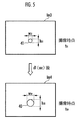
続くSTEP4〜STEP6は監視対象物抽出手段20による処理である。監視対象物抽出手段20は、STEP4で2値画像中の白の各領域のランレングスデータを算出し、STEP5で水平方向に重なる部分がある領域を1つの対象物としてラベルを付するラベリング処理を行う。そして、次のSTEP6で、画像処理ユニット1は、ラベルが付された領域の中から監視対象物に対応すると判断される領域(本発明の監視対象物の画像部分に相当する)を抽出し、STEP7で、抽出された領域の重心G、面積S、及び外接四角形の縦横比(ASPECT)を算出する。次のSTEP8は変化率算出手段21による処理である。
変化率算出手段21は、図5に示したように、前回(撮像時点t21)の撮像画像の2値画像Im3と、今回(撮像時点t20)の撮像画像の2値画像Im4間で、同一の監視対象物に対応した領域を追跡する処理を行う。具体的には、以下の(a)〜(c)の要件を満たす領域を、同一の監視対象物に対応した領域であると判定する追跡処理を行う。 Change rate calculating means 21, as shown in FIG. 5, a binary image Im3 of the captured image of the previous pick-up time (t 21), this time between the binary image Im4 the captured image pick-up time (t 20), A process for tracking an area corresponding to the same monitoring object is performed. Specifically, a tracking process for determining that an area satisfying the following requirements (a) to (c) is an area corresponding to the same monitoring object is performed.
(a) 前回(撮像時点t21)の撮像画像の2値画像Im3における監視対象物に対応した領域41の重心位置座標を(x21,y21)とし、今回(撮像時点t20)の撮像画像の2値画像における監視対象物に対応した領域40の重心位置座標を(x20,y20)としたときに、以下の式(3)及び式(4)の関係を満たすこと。
(a) The center-of-gravity position coordinates of the
![]()
![]()
但し、Δx:x方向(水平方向)の画像上の移動量の許容値。 However, Δx is an allowable value of the movement amount on the image in the x direction (horizontal direction).
![]()
![]()
但し、Δy:y方向(垂直方向)の画像上の移動量の許容値。 However, Δy: an allowable value of the movement amount on the image in the y direction (vertical direction).
(b) 前回(撮像時点t21)の撮像画像の2値画像Im3における監視対象物に対応した領域41の面積をS21とし、今回(撮像時点t20)の撮像画像の2値画像Im4における監視対象物に対応した領域40の面積をS20としたときに、以下の式(5)の関係を満たすこと。
(b) the last of the area of the
但し、ΔS:面積変化の許容値。 However, ΔS: allowable value of area change.
(c) 前回(撮像時点t21)の撮像画像の2値画像Im3における監視対象物に対応した領域41の縦横比をAS21とし、今回(撮像時点t20)の撮像画像の2値画像Im4における監視対象物に対応した領域40の縦横比をAS20としたときに、以下の式(6)の関係を満たすこと。
(c) the previous aspect ratio of the
但し、ΔAS:縦横比変化の許容値。 However, ΔAS: allowable value of change in aspect ratio.
変化率算出手段21は、前回(撮像時点t21)の撮像画像の2値画像Im3における監視対象物に対応した領域41と、今回(撮像時点t20)の撮像画像の2値画像Im4における監視対象物に対応した領域40について、上記(a)〜(c)の関係が成立したときに、領域41と領域40は同一の監視対象物に対応したものであると判断する。そして、変化率算出手段21は、上記式(1)により、抽出領域41の幅w21を抽出領域40の幅w20で除して、変化率Rateを算出する。
Change rate calculating means 21 includes an
次のSTEP9は到達時間推定手段22による処理であり、到達時間推定手段22は、上記式(2)により、変化率Rateを用いて自車両到達時間Tを算出する。また、STEP10は実空間位置算出手段23による処理であり、実空間位置算出手段23は、上記式(1)による以下の式(7)において、自車両10と監視対象物間の相対速度Vs(=車両の走行速度Vj+監視対象物の移動速度Vd)を、自車両10の速度Vjが監視対象物の移動速度Vdよりも十分に高いとみなして、自車両10の走行速度Vjに置き換えて変形した以下の式(8)により、今回の監視対象物までの距離Z0を算出する。
The next STEP 9 is processing by the arrival time estimation means 22, and the arrival time estimation means 22 calculates the own vehicle arrival time T using the rate of change Rate according to the above equation (2). Further,
但し、Rate:変化率、Z0:今回の監視対象物までの距離、Vs:車両と監視対象物間の相対速度、dT:撮像間隔。 Where Rate: rate of change, Z 0 : distance to the current monitoring object, Vs: relative speed between the vehicle and the monitoring object, dT: imaging interval.
但し、Z0:今回の監視対象物までの距離、Rate:変化率、Vj:車両の走行速度、dT:撮像間隔。 However, Z 0 : Distance to the current monitoring object, Rate: Rate of change, Vj: Traveling speed of vehicle, dT: Imaging interval.
また、実空間位置算出手段23は、前回の撮像時における監視対象物までの距離Z1を、以下の式(9)により算出する。
Moreover, the real space
![]()
![]()
但し、Z1:前回の撮像時における監視対象物までの距離、Z0:今回の撮像時における監視対象物までの距離、Vj:車両の走行速度、dT:撮像間隔。 However, Z 1 : distance to the monitoring object at the time of previous imaging, Z 0 : distance to the monitoring object at the time of current imaging, Vj: traveling speed of the vehicle, dT: imaging interval.
上記式(8)と式(9)により、実空間位置算出手段23は、今回の撮像時における車両10から監視対象物までの距離Z0と、前回の撮像時における車両10から監視対象物までの距離Z1とを算出する。そして、続くSTEP11で、実空間位置算出手段23は、今回及び前回の2値画像における監視対象物に対応した領域の位置から、今回及び前回の撮像時における監視対象物の実空間位置を算出する。
From the above formulas (8) and (9), the real space position calculating means 23 calculates the distance Z 0 from the
ここで、図6(a)は、2値画像Im5上の今回の監視対象物の抽出位置Pi_0(x10,y10)と、前回の監視対象物の抽出位置Pi_1(x11,y11)を示しており、縦軸yが画像の垂直方向に設定され、横軸xが画像の水平方向に設定されている。 Here, FIG. 6 (a), the extraction position of the current monitored object on the binary image Im5 Pi_0 (x 10, y 10 ), extracting the position of the previous monitored object Pi_1 (x 11, y 11) The vertical axis y is set in the vertical direction of the image, and the horizontal axis x is set in the horizontal direction of the image.
また、図6(b)は実空間上の監視対象物の移動状況を示しており、Z軸が車両10の進行方向に設定され、X軸がZ軸と直交する方向に設定されている。そして、図中Pr_0(X10,Y10,Z10)は今回の撮像時における監視対象物の位置を示し、Pr_1(X11,Y11,Z11)は前回の撮像時における監視対象物の位置を示している。また、Vmは、Pr_0とPr_1から推定した監視対象物の移動ベクトルである。
FIG. 6B shows the movement state of the monitoring object in the real space, where the Z axis is set in the traveling direction of the
実空間位置算出手段23は、STEP11で、以下の式(10)により今回の撮像時における監視対象物の実空間座標Pr_0(X10,Y10,Z10)を算出し、以下の式(11)により前回の撮像時における監視対象物の実空間座標Pr_1(X11,Y11,Z11)を算出する。 In STEP 11, the real space position calculation means 23 calculates the real space coordinates Pr_0 (X 10 , Y 10 , Z 10 ) of the monitoring object at the time of the current imaging according to the following equation (10). ) To calculate the real space coordinates Pr_1 (X 11 , Y 11 , Z 11 ) of the monitored object at the time of the previous imaging.
但し、X10,Y10:今回の撮像時における監視対象物の実空間座標値、x10,y10:今回の撮像画像の2値画像における監視対象物に対応した領域の画像座標値、Z0:今回の撮像時における車両から監視対象物までの距離、f:f=F(赤外線カメラの焦点距離)/p(撮像画像の画素ピッチ)。 However, X 10, Y 10: a real space coordinate values of the current monitored object at imaging, x 10, y 10: image coordinate values of the area corresponding to the monitored object in the binary image of the current captured image, Z 0 : distance from the vehicle to the monitoring object at the time of the current imaging, f: f = F (focal distance of infrared camera) / p (pixel pitch of the captured image).
但し、X11,Y11:前回の撮像時における監視対象物の実空間座標値、x11,y11:前回の撮像画像の2値画像における監視対象物に対応した領域の画像座標値、Z1:前回の撮像時における車両から監視対象物までの距離、f:f=F(赤外線カメラの焦点距離)/p(撮像画像の画素ピッチ)。 X 11 , Y 11 : real space coordinate value of the monitoring object at the previous imaging, x 11 , y 11 : image coordinate value of the area corresponding to the monitoring object in the binary image of the previous imaging image, Z 1 : Distance from vehicle to monitoring object at the time of previous imaging, f: f = F (focal distance of infrared camera) / p (pixel pitch of captured image).
また、次のSTEP12で、実空間位置算出手段23は、車両10が回頭することによる画像上の位置ずれを、ヨーレートセンサ3の検出信号YRから認識される回頭角に基づいて補正する回頭角補正を行う。具体的には、前回の撮像時から今回の撮像時までの間における車両10の回頭角がθrであったときに、以下の式(12)により実空間座標値を補正する。
In the next STEP 12, the real space position calculation means 23 corrects the positional deviation on the image due to the turning of the
但し、Xr,Yr,Zr:回頭角補正後の実空間座標値、θr:回頭角、Xo,Yo,Zo:回頭角補正前の実空間座標値。 However, Xr, Yr, Zr: real space coordinate value after turning angle correction, θr: turning angle, Xo, Yo, Zo: real space coordinate value before turning angle correction.
続くSTEP13は移動ベクトル算出手段24による処理であり、移動ベクトル算出手段24は、図6(b)に示したように、同一の監視対象物についての前回の撮像時の実空間位置Pr_1と今回の撮像時の実空間位置Pr_0から、監視対象物と自車両10との相対移動ベクトルに対応する近似直線Vmを求める。なお、過去の複数時点における監視対象物の実空間位置を用いて、相対移動ベクトルを求めるようにしてもよい。また、近似直線の具体的な算出処理は、前掲した特開2001−6096号公報に記載された手法による。
The subsequent STEP 13 is processing by the movement vector calculation means 24. As shown in FIG. 6B, the movement vector calculation means 24 determines the actual space position Pr_1 at the time of previous imaging of the same monitoring object and the current time. From the real space position Pr_0 at the time of imaging, an approximate straight line Vm corresponding to the relative movement vector between the monitored object and the
このように、監視対象物の自車両10に対する相対移動軌跡を近似する近似直線を算出して相対移動ベクトルを求め、該移動ベクトルとZ軸との交差の有無を判断することにより、位置検出誤差の影響を軽減して監視対象物との接触の可能性をより正確に予測することができる。
In this way, by calculating an approximate straight line that approximates the relative movement trajectory of the monitoring object with respect to the
続くSTEP14〜STEP15及びSTEP20は、接触判定手段25による処理であり、接触判定手段25は、STEP14で以下の式(13)によりZ方向(車両10の進行方向)の相対速度Vsを算出し、以下の式(14)及び式(15)により監視対象物との接触可能性を判別する。 Subsequent STEP14 to STEP15 and STEP20 are processes by the contact determination means 25, and the contact determination means 25 calculates the relative speed Vs in the Z direction (traveling direction of the vehicle 10) by the following expression (13) in STEP14. The possibility of contact with the monitoring object is discriminated by the equations (14) and (15).
但し、Vs:監視対象物と車両間の相対速度、Z11:前回の撮像時におけるZ方向の実空間座標値、Z10:今回の撮像時におけるZ方向の実空間座標値、dT:撮像間隔。 However, Vs: relative speed between the monitored object and the vehicle, Z 11: the real space coordinate value in the Z direction at the previous imaging, Z 10: the real space coordinate value in the Z-direction at the time of current imaging, dT: imaging interval .
但し、Z10:今回の撮像時における監視対象物のZ方向の実空間座標値、Vs:監視対象物と車両間の相対速度、Tl:余裕時間閾値。 However, Z 10 : real space coordinate value of the monitoring object in the Z direction at the time of the current imaging, Vs: relative speed between the monitoring object and the vehicle, and Tl: margin time threshold.
但し、Y10:今回の撮像時における監視対象物のY方向(高さ方向)の実空間座標値、Hl:高さ閾値。 Where Y 10 is a real space coordinate value in the Y direction (height direction) of the monitoring object at the time of the current imaging, and H 1 is a height threshold value.
なお、上記式(14)におけるTlは、接触の可能性を予測接触時刻よりもTl時間だけ以前に判定することを意図したものであり、例えば2〜5秒程度に設定される。また、上記式(15)におけるHlは、高さ方向の範囲を規定するものであり、例えば車両10の車高の2倍程度に設定される。
In addition, Tl in the above formula (14) is intended to determine the possibility of contact by Tl time before the predicted contact time, and is set to, for example, about 2 to 5 seconds. Further, Hl in the above equation (15) defines a range in the height direction, and is set to about twice the vehicle height of the
接触判定手段25は、上記式(14)及び式(15)の関係が成立するときは、接触の可能性があると判断し、上記式(14)及び式(15)のいずれかが不成立であるときには、接触の可能性がないと判断する。接触の可能性があると判断したときは、次のSTEP15からSTEP20に進み、接触判定手段25は、スピーカ6により警報音を発すると共にHUD7により警報表示をしてSTEP1に戻る。一方、接触の可能性がないと判断したときには、STEP16からSTEP1に進み、スピーカ6による警報音の出力とHUD7による警報表示は行われない。
The contact determination means 25 determines that there is a possibility of contact when the relationship of the above expressions (14) and (15) is established, and either of the above expressions (14) and (15) is not satisfied. In some cases, it is determined that there is no possibility of contact. When it is determined that there is a possibility of contact, the process proceeds from STEP 15 to STEP 20, and the contact determination means 25 emits an alarm sound from the speaker 6 and displays an alarm by the HUD 7 and returns to STEP 1. On the other hand, when it is determined that there is no possibility of contact, the process proceeds from STEP 16 to
なお、本実施の形態において、変化率算出手段21は、図5に示した2値画像間の同一監視対象物の時間追跡処理により変化率Rateを算出したが、図7に示した監視対象物の画像部分の相間演算により変化率Rateを算出するようにしてもよい。図7を参照して、Im6は前回の撮像時におけるグレースケール画像であり、51は監視対象物の画像部分を示している。また、Im7は今回の撮像時におけるグレースケール画像であり、50は監視対象物の画像部分を示している。 In the present embodiment, the change rate calculation means 21 calculates the change rate Rate by the time tracking process of the same monitoring object between the binary images shown in FIG. 5, but the monitoring object shown in FIG. The rate of change Rate may be calculated by the inter-phase calculation of the image portions. Referring to FIG. 7, Im6 is a gray scale image at the time of previous imaging, and 51 indicates an image portion of the monitoring object. Further, Im7 is a gray scale image at the time of the current imaging, and 50 indicates an image portion of the monitoring object.
そして、変化率算出手段21は、今回のグレースケール画像Im7における監視対象物の画像部分50の大きさをアフィン変換により縮小(監視対象物が自車両に近づいている場合)又は拡大(監視対象物が自車両から遠ざかっている場合)して、前回の撮像時における監視対象物の画像部分51との相間度を算出する。具体的には、図示したように、画像部分50を1.5倍した画像60,1.25倍した画像61、1.0倍した画像62、0.75倍した画像63、0.5倍した画像64と、画像部分51との相間度を算出する。そして、変化率算出手段21は、相間度が最も高くなったときの画像部分50の倍率を変化率Rateとして決定する。
The rate-of-change calculating means 21 reduces or enlarges the size of the
なお、本第2の実施の形態においては、図4のSTEP14で監視対象物の実空間における移動ベクトルを求めて、上記式(14),式(15)により監視対象物と自車両10との接触可能性を判定したが、上記式(14)に変えて、STEP9で上記式(2)により算出した自車両到達時間Tを用いて、監視対象物と自車両10との接触可能性を判定するようにしてもよい。
In the second embodiment, the movement vector in the real space of the monitoring object is obtained in STEP 14 of FIG. 4, and the monitoring object and the
また、図4のSTEP9で推定した自車両到達時間Tを用いて、直接的に自車両の周辺を監視するようにしてもよい。例えば、自車両到達時間Tが所定の下限時間以下となったときに、運転者に対して警報を発するようにしてもよい。 Moreover, you may make it monitor the periphery of the own vehicle directly using the own vehicle arrival time T estimated by STEP9 of FIG. For example, an alarm may be issued to the driver when the own vehicle arrival time T becomes equal to or shorter than a predetermined lower limit time.
[第3の実施の形態]次に、本発明の第3の実施の形態における画像処理ユニット1による監視対象物と自車両10との接触判定処理の実行手順について、図8に示したフローチャートに従って説明する。図8のSTEP30〜STEP37は上述した図4のSTEP1〜STEP8と同様の処理であり、STEP37で、変化率算出手段21により変化率Rateが算出される。
[Third Embodiment] Next, according to the flowchart shown in FIG. 8, the execution procedure of the contact determination process between the monitored object and the
続くSTEP38は位置変化量算出手段26による処理であり、位置変化量算出手段26は、STEP37の時間間追跡で用いられた複数の画像における同一の監視対象物の画像部分の位置変化量Δx(水平方向),Δy(垂直方向)を算出する。次のSTEP39〜STEP40及びSTEP50は、接触判定手段25による処理であり、接触判定手段25は、STEP39で以下の条件1及び条件2が共に成立するか否かにより、自車両10と監視対象物との接触可能性の有無を判別する。
The subsequent STEP 38 is a process performed by the position change amount calculating means 26. The position change amount calculating means 26 is the position change amount Δx (horizontal) of the image portion of the same monitored object in the plurality of images used in the time tracking of STEP 37. Direction), Δy (vertical direction). The next STEP 39 to STEP 40 and
条件1: 同一の監視対象物についての画像部分の面積が、前回の撮像画像よりも今回の撮像画像の方が大きい。すなわち、監視対象物と自車両10が近付いている。接触判定手段25は、この条件1が成立するか否かを以下の式(16)により判断する。
Condition 1: The area of the image portion for the same monitoring object is larger in the current captured image than in the previous captured image. That is, the monitoring object and the
条件2: 変化率Rateを求めたときの撮像画像間における同一の監視対象物の画像部分の位置がほとんど変化していない。すなわち、時間が経過したにも拘らず画像上では該画像部分が静止している。接触判定手段25は、この条件2が成立するか否かを以下の式(17),式(18)により判断する。
Condition 2: The position of the image portion of the same monitoring object between the captured images when the change rate Rate is obtained hardly changes. That is, the image portion is stationary on the image despite the passage of time. The contact determination means 25 determines whether or not the
![]()
![]()
![]()
![]()
但し、(x0,y0):今回の撮像画像における監視対象物の画像部分の重心位置、Thx:x方向の位置変化閾値、(x1,y1):前回の撮像画像における同一の監視対象物の画像部分の重心位置、Thy:y方向の位置変化閾値。 However, (x 0 , y 0 ): the barycentric position of the image portion of the monitoring object in the current captured image, Thx: the position change threshold value in the x direction, (x 1 , y 1 ): the same monitoring in the previous captured image The barycentric position of the image portion of the object, Thy: a position change threshold value in the y direction.
ここで、図9(a),図9(b)を参照して、上記条件2について説明する。図9(a)は、自車両10に対して、監視対象物70が自車両10の進行方向(Z方向)の相対速度Vs、進行方向と直交する方向(X方向)の進入速度Vdで接近している状況を示している。そして、t31の時点(前回の撮像時)における監視対象物70の実空間位置が(X31,Z31)、t31からdT(撮像間隔)が経過したt30の時点(今回の撮像時)における監視対象物70の実空間位置が(X30,Z30)となっている。
Here, the
図9(a)において、自車両10からは監視対象物70が以下の式(19)で表されるθの方向に見える。そして、自車両10と接触する監視対象物70は、時間が経過してもθが一定となる。
In FIG. 9A, the monitored
θが一定であることから、以下の式(20)が成立する。 Since θ is constant, the following equation (20) is established.
但し、ΔT:経過時間。 However, ΔT: elapsed time.
図9(b)は図9(a)の状況を、以下の式(21),式(22)の透視変換により画像Im8に表したものである。図9(b)中、80はt31の時点の監視対象物70の画像部分であり、81はt30の時点の監視対象物70の画像部分である。
FIG. 9B shows the situation of FIG. 9A in the image Im8 by the perspective transformation of the following equations (21) and (22). In FIG. 9 (b), 80 is an image portion of the monitored
なお、実空間上のY方向(自車両10の高さ方向)とZ方向との関係も、X方向とZ方向と同様であり、透視変換により、t30 の時点における監視対象物70の実空間位置Y30に対する画像上の位置y30と、t31 の時点における監視対象物70の実空間位置Y31に対する画像上の位置y31を求めることができる。
Incidentally, the relationship between the Z-direction (height direction of the vehicle 10) Y-direction in the real space, the same as the X and Z directions, by the perspective transformation, the monitored
但し、f:f=F(赤外線カメラの焦点距離)/p(撮像画像の画素ピッチ)。 However, f: f = F (focal length of the infrared camera) / p (pixel pitch of the captured image).
上記式(21),式(22)の右辺のX30/Z30とX31/Z31は上記式(20)より等しいため、x30=x31となる。同様に、Y方向についてもy30=y31となる。そのため、図9(a)に示した自車両10と監視対象物70が接触する状況にあるときは、図9(b)に示したように、画像上では監視対象物70の今回の画像部分80及び前回の画像部分81の重心位置が等しくなることがわかる。上記条件2は、この状況を自車両10と監視対象物の接触可能性の判断条件としたものである。
Since X 30 / Z 30 and X 31 / Z 31 on the right side of the above formulas (21) and (22) are equal to those in the above formula (20), x 30 = x 31 . Similarly, y 30 = y 31 in the Y direction. Therefore, when the
上記条件1及び条件2による場合には、複数の撮像画像における同一の監視対象物の画像部分について、変化率Rate及び位置変化量Δx,Δyを算出するという簡易な演算処理により、自車両10と監視対象物との接触可能性の有無を判断することができる。そのため、上述した第1の実施の形態において必要であった自車両10と監視対象物との距離の算出や、移動ベクトル推定の処理は不要である。
In the case of the
そして、接触判定手段25は、上記条件1及び上記条件2が共に成立して接触の可能性があると判断したときはSTEP40からSTEP50に分岐して、スピーカ6により警報音を発すると共にHUD7により警報表示をしてSTEP30に戻る。一方、上記条件1と上記条件2のうちの少なくともいずれか一方が成立せず、接触の可能性がないと判断したときにはSTEP40からSTEP30に進み、スピーカ6による警報音の出力とHUD7による警報表示は行われない。
Then, the
なお、上記条件2の上記式(17)における位置変化閾値Thx及び上記式(18)における位置変化閾値Thyは、自車両10の車幅及び車高に基づく固定値としてもよいが、位置変化閾値設定手段27により、自車両10と監視対象物間の距離に応じて設定するようにしてもよい。以下、図10(a),図10(b)を参照して、自車両10と監視対象物間の距離に応じて、位置変化閾値Thx及びThyを設定する処理について説明する。
Note that the position change threshold Thx in the expression (17) of the
ここで、自車両10と監視対象物間の距離は、上述した第1の実施の形態における上記式(8),式(9)により算出してもよく、レーダ等を用いた測距センサ(本発明の測距手段に相当する)により検出してもよい。
Here, the distance between the
図10(a)は、自車両10の位置を原点とした実空間上の2次元座標で、監視対象物の位置の推移を示したものであり、縦軸がZ(自車両10の進行方向)に設定され、横軸がX(Z軸と直交する方向、自車両の幅方向)に設定されている。また、Yは自車両10の車高方向(Z−X平面と直交する方向)である。
FIG. 10A is a two-dimensional coordinate in the real space with the position of the
図10(a)中、2aは自車両10の車幅であり、Pr_2(X40,Y40,Z40)は監視対象物の今回の撮像時の実空間上の座標、Pr_3(X41,Y41,Z41)は監視対象物の前回の撮像時の実空間上の座標である。また、図10(b)は、図10(a)の監視対象物の実空間上の座標Pr_2(X40,Y40,Z40),Pr_3(X41,Y41,Z41)にそれぞれ対応する画像Im9上の座標Pi_2(x40,y40),Pi_3(x41,y41)を示している。図10(a)において、Pr_2とPr_3を通る直線Vlは、以下の式(23)で表される。
In FIG. 10A, 2a is the vehicle width of the
そして、直線Vlが−a〜aの範囲でX軸と交わるとき、すなわち、上記式(23)でZ=0としたときに|X|<aの条件が満たされるときには、自車両10が監視対象物と接触する。そこで、上記式(23)にZ=0を代入すると、この条件は以下の式(24)で表される。
When the straight line Vl intersects the X axis in the range of −a to a, that is, when the condition | X | <a is satisfied when Z = 0 in the above equation (23), the
但し、a:自車両の幅の1/2。 However, a: 1/2 of the width of the own vehicle.
上記式(24)のX40,X41を以下の式(25),式(26)による逆透視変換により、画像上の水平座標x40,x41に変換すると、以下の式(27)が得られる。 When X 40 and X 41 in the above equation (24) are converted into horizontal coordinates x 40 and x 41 on the image by inverse perspective transformation according to the following equations (25) and (26), the following equation (27) is obtained. can get.
但し、f:f=F(赤外線カメラの焦点距離)/p(撮像画像の画素ピッチ)。 However, f: f = F (focal length of the infrared camera) / p (pixel pitch of the captured image).
上記式(27)を整理すると、以下の式(28)が得られる。そこで、位置変化量算出手段26は、以下の式(28)の右辺を上記条件2の位置変化閾値Thxとする。
By arranging the above equation (27), the following equation (28) is obtained. Therefore, the position change amount calculation means 26 sets the right side of the following expression (28) as the position change threshold Thx of the
但し、f:f=F(赤外線カメラの焦点距離)/p(撮像画像の画素ピッチ)、a:自車両の車幅の1/2。 However, f: f = F (focal length of the infrared camera) / p (pixel pitch of the captured image), a: 1/2 of the vehicle width of the host vehicle.
また、自車両10の車高を2bとすると、上述したX方向についての接触可能性と同様に、Y方向についても以下の式(29)の右辺を上記条件2の位置変化閾値Thyとして設定することができる。
Further, when the vehicle height of the
但し、f:f=F(赤外線カメラの焦点距離)/p(撮像画像の画素ピッチ)、b:自車両の車高の1/2。 However, f: f = F (focal length of the infrared camera) / p (pixel pitch of the captured image), b: 1/2 of the vehicle height of the own vehicle.
このように、位置変化閾値設定手段27により自車両10と監視対象物間の距離に基づいて位置変化閾値Thx,Thyを設定することによって、図10(a)に示した直線Vlによる監視対象物の移動軌跡を想定して自車両10と監視対象物との接触可能性を判断することができるため、接触判定手段25による接触判定の精度を高めることができる。
In this way, the position change threshold value setting means 27 sets the position change threshold values Thx and Thy based on the distance between the
[第4の実施の形態]次に、本発明の第4の実施の形態における画像処理ユニット1による監視対象物と自車両10との接触判定処理の実行手順について説明する。第4の実施の形態は、前記第3の実施の形態における条件1及び条件2に、以下の条件3を追加して、監視対象物と自車両10との接触可能性を判定するものである。
[Fourth Embodiment] Next, an execution procedure of the contact determination process between the monitoring object and the
条件3: 監視対象物が自車両10に到達するまでの時間(自車両到達時間)Tが、所定時間以下であること。接触判定手段25は、この条件3が成立するか否かを以下の式(30)により判断する。
Condition 3: The time (host vehicle arrival time) T until the monitored object reaches the
但し、Rate:上記式(16)により算出した監視対象物の画像部分の面積の変化率、dT:撮像間隔、T:自車両到達時間(前記所定時間を代入する)。 However, Rate: change rate of the area of the image portion of the monitoring target calculated by the above equation (16), dT: imaging interval, T: own vehicle arrival time (the predetermined time is substituted).
このように、前記条件3を加えて監視対象物と自車両10との接触可能性を判定することにより、接触判定手段25は、自車両10に到達するまでの時間Tが所定時間以下である緊急性の高い監視対象物に限定して、接触可能性が高いと判断することができる。
In this way, by adding the
なお、本実施の形態においては、本発明の撮像手段として赤外線カメラ2を用いたが、可視光のみを検出可能な通常のビデオカメラを用いてもよい。
In the present embodiment, the
また、本実施の形態においては、車両前方を撮像する構成を示したが、車両の後方や側方等、他の方向を撮像して監視対象物との接触可能性を判断するようにしてもよい。 Further, in the present embodiment, the configuration in which the front of the vehicle is imaged is shown, but it is also possible to determine the possibility of contact with the monitoring object by imaging other directions such as the rear and side of the vehicle. Good.
1…画像処理ユニット、2…赤外線カメラ(撮像手段)、3…ヨーレートセンサ、4…車速センサ、5…ブレーキセンサ、6…スピーカ、7…HUD、20…監視対象物抽出手段、21…変化率算出手段、22…到達時間推定手段、23…実空間位置算出手段、24…移動ベクトル算出手段、25…接触判定手段、26…位置変化量算出手段、27…位置変化閾値設定手段
DESCRIPTION OF
Claims (4)
前記撮像手段により撮像された画像から、監視対象物の画像部分を抽出する監視対象物抽出手段と、
所定時間間隔をもって前記撮像手段により撮像された複数の画像から、前記監視対象物抽出手段により抽出された同一の監視対象物の画像部分の大きさの変化率を算出する変化率算出手段と、
前記所定時間間隔をもって前記撮像手段により撮像された複数の画像から、前記監視対象物抽出手段により抽出された同一の監視対象物の画像部分の位置変化量を算出する位置変化量算出手段と、
所定時点から前記所定時間間隔をもって前記撮像手段により撮像された複数の画像から、前記監視対象物抽出手段により抽出された同一の監視対象物の画像部分について、前記変化率算出手段により算出された該画像部分の大きさの変化率が該画像部分の拡大を示すものであり、且つ、前記位置変化量算出手段により算出された該画像部分の位置変化量が所定の位置変化閾値以下であるときに、監視対象物と前記車両との接触可能性が高いと判断する接触判定手段とを備え、
前記監視対象物抽出手段は、前記撮像手段により撮像された画像から抽出する監視対象物の画像部分を、該撮像された画像を各画素の輝度に応じて2値化処理して生成した2値画像から抽出したものとし、
前記変化率算出手段は、画像部分が同一の監視対象物の画像部分であることを、画像部分の面積の変化率に基づいて判定するとともに、前記大きさの変化率として画像部分の面積の変化率を用いることを特徴とする車両周辺監視装置。 In a vehicle periphery monitoring device that detects a monitoring object around the vehicle from an image captured by a single imaging unit mounted on the vehicle,
Monitoring object extraction means for extracting an image portion of the monitoring object from the image captured by the imaging means;
A change rate calculating means for calculating a change rate of the size of the image portion of the same monitoring object extracted by the monitoring object extracting means from a plurality of images taken by the imaging means at a predetermined time interval;
A position change amount calculating means for calculating a position change amount of an image portion of the same monitoring object extracted by the monitoring object extracting means from a plurality of images taken by the imaging means at the predetermined time interval;
The image rate of the same monitoring object extracted by the monitoring object extraction unit from the plurality of images captured by the imaging unit at a predetermined time interval from a predetermined time point is calculated by the change rate calculation unit. When the rate of change of the size of the image portion indicates the enlargement of the image portion, and the position change amount of the image portion calculated by the position change amount calculation means is less than or equal to a predetermined position change threshold A contact determination means for determining that there is a high possibility of contact between the monitoring object and the vehicle ,
The monitoring object extraction unit generates a binary image obtained by binarizing the image portion of the monitoring object extracted from the image captured by the imaging unit according to the luminance of each pixel. Suppose it was extracted from the image,
The change rate calculating means determines that the image portions are image portions of the same monitoring object based on the change rate of the area of the image portion, and changes the area of the image portion as the change rate of the size. A vehicle periphery monitoring device using a rate .
前記接触判定手段は、所定時点から前記所定時間間隔をもって前記撮像手段により撮像された複数の画像から、前記監視対象物抽出手段により抽出された同一の監視対象物の画像部分について、前記変化率算出手段により算出された該画像部分の大きさの変化率が該画像部分の拡大を示すものであり、且つ、前記位置変化量算出手段により算出された該画像部分の位置変化量が所定の位置変化閾値以下であり、且つ、前記到達時間推定手段により推定された前記自車両到達時間が所定時間以下であるときに、監視対象物と前記車両との接触可能性が高いと判断することを特徴とする請求項1記載の車両周辺監視装置。 Based on the rate of change, an arrival time estimation means for estimating a host vehicle arrival time which is a time until the monitoring target arrives at the vehicle,
The contact determination unit calculates the rate of change for an image portion of the same monitoring object extracted by the monitoring object extraction unit from a plurality of images captured by the imaging unit at a predetermined time interval from a predetermined time point. The change rate of the size of the image portion calculated by the means indicates the enlargement of the image portion, and the position change amount of the image portion calculated by the position change amount calculation means is a predetermined position change. When the vehicle arrival time estimated by the arrival time estimation means is equal to or less than a predetermined time and less than a predetermined time, it is determined that the possibility of contact between the monitoring object and the vehicle is high. The vehicle periphery monitoring device according to claim 1 .
前記車両と監視対象物間の距離に応じて、前記位置変化閾値を設定する位置変化閾値設定手段とを備えたことを特徴とする請求項1又は請求項2記載の車両周辺監視装置。 Distance measuring means for detecting a distance between the vehicle and the monitoring object;
Said vehicle and according to the distance between the monitored object, the location to set the variation threshold position variation threshold setting means and the vehicle periphery monitoring device according to claim 1 or claim 2, wherein further comprising a.
Priority Applications (3)
| Application Number | Priority Date | Filing Date | Title |
|---|---|---|---|
| JP2006349746A JP4970926B2 (en) | 2006-01-16 | 2006-12-26 | Vehicle periphery monitoring device |
| US11/653,149 US7586400B2 (en) | 2006-01-16 | 2007-01-12 | Vehicle surroundings monitoring apparatus |
| DE102007002345A DE102007002345B4 (en) | 2006-01-16 | 2007-01-16 | Vehicle environment monitoring device |
Applications Claiming Priority (3)
| Application Number | Priority Date | Filing Date | Title |
|---|---|---|---|
| JP2006007019 | 2006-01-16 | ||
| JP2006007019 | 2006-01-16 | ||
| JP2006349746A JP4970926B2 (en) | 2006-01-16 | 2006-12-26 | Vehicle periphery monitoring device |
Publications (3)
| Publication Number | Publication Date |
|---|---|
| JP2007213561A JP2007213561A (en) | 2007-08-23 |
| JP2007213561A5 JP2007213561A5 (en) | 2008-06-19 |
| JP4970926B2 true JP4970926B2 (en) | 2012-07-11 |
Family
ID=38284969
Family Applications (1)
| Application Number | Title | Priority Date | Filing Date |
|---|---|---|---|
| JP2006349746A Active JP4970926B2 (en) | 2006-01-16 | 2006-12-26 | Vehicle periphery monitoring device |
Country Status (3)
| Country | Link |
|---|---|
| US (1) | US7586400B2 (en) |
| JP (1) | JP4970926B2 (en) |
| DE (1) | DE102007002345B4 (en) |
Families Citing this family (49)
| Publication number | Priority date | Publication date | Assignee | Title |
|---|---|---|---|---|
| US7561720B2 (en) * | 2004-04-30 | 2009-07-14 | Visteon Global Technologies, Inc. | Single camera system and method for range and lateral position measurement of a preceding vehicle |
| US7561721B2 (en) * | 2005-02-02 | 2009-07-14 | Visteon Global Technologies, Inc. | System and method for range measurement of a preceding vehicle |
| US20070031008A1 (en) * | 2005-08-02 | 2007-02-08 | Visteon Global Technologies, Inc. | System and method for range measurement of a preceding vehicle |
| US7623681B2 (en) * | 2005-12-07 | 2009-11-24 | Visteon Global Technologies, Inc. | System and method for range measurement of a preceding vehicle |
| JP4893945B2 (en) * | 2007-02-06 | 2012-03-07 | 株式会社デンソー | Vehicle periphery monitoring device |
| US20090005948A1 (en) * | 2007-06-28 | 2009-01-01 | Faroog Abdel-Kareem Ibrahim | Low speed follow operation and control strategy |
| KR100933304B1 (en) | 2007-08-30 | 2009-12-22 | 중앙대학교 산학협력단 | An object information estimator using the single camera, a method thereof, a multimedia device and a computer device including the estimator, and a computer-readable recording medium storing a program for performing the method. |
| JP4359710B2 (en) * | 2008-02-04 | 2009-11-04 | 本田技研工業株式会社 | Vehicle periphery monitoring device, vehicle, vehicle periphery monitoring program, and vehicle periphery monitoring method |
| JP4521642B2 (en) * | 2008-02-13 | 2010-08-11 | 本田技研工業株式会社 | Vehicle periphery monitoring device, vehicle, vehicle periphery monitoring program |
| JP4486997B2 (en) * | 2008-04-24 | 2010-06-23 | 本田技研工業株式会社 | Vehicle periphery monitoring device |
| JP4271720B1 (en) * | 2008-04-24 | 2009-06-03 | 本田技研工業株式会社 | Vehicle periphery monitoring device |
| JP4644273B2 (en) * | 2008-07-15 | 2011-03-02 | 本田技研工業株式会社 | Vehicle periphery monitoring device |
| JP5602354B2 (en) * | 2008-10-08 | 2014-10-08 | 本田技研工業株式会社 | Vehicle periphery monitoring device |
| JP4864953B2 (en) * | 2008-10-08 | 2012-02-01 | 本田技研工業株式会社 | Vehicle periphery monitoring device |
| JP2010108264A (en) * | 2008-10-30 | 2010-05-13 | Honda Motor Co Ltd | Vehicle periphery monitoring device |
| KR101023275B1 (en) * | 2009-04-06 | 2011-03-18 | 삼성전기주식회사 | Calibration method and apparatus for automotive camera system, and method and ecu for determining angular misalignments of automotive camera system |
| JP5430213B2 (en) * | 2009-04-24 | 2014-02-26 | 本田技研工業株式会社 | Vehicle periphery monitoring device |
| JP4733756B2 (en) * | 2009-04-28 | 2011-07-27 | 本田技研工業株式会社 | Vehicle periphery monitoring device |
| WO2011065149A1 (en) | 2009-11-25 | 2011-06-03 | 本田技研工業株式会社 | Target-object distance measuring device and vehicle mounted with the device |
| JP2011192141A (en) * | 2010-03-16 | 2011-09-29 | Sony Corp | Moving body detecting device and moving body detection method and program |
| WO2012004938A1 (en) * | 2010-07-09 | 2012-01-12 | 本田技研工業株式会社 | Device for monitoring vicinity of vehicle |
| WO2012029382A1 (en) | 2010-08-31 | 2012-03-08 | 本田技研工業株式会社 | Vehicle surroundings monitoring device |
| JP5529058B2 (en) * | 2011-02-24 | 2014-06-25 | アルパイン株式会社 | Three-dimensional object detection device and three-dimensional object detection method |
| JP5603835B2 (en) | 2011-06-27 | 2014-10-08 | クラリオン株式会社 | Vehicle perimeter monitoring device |
| US9292735B2 (en) * | 2011-09-28 | 2016-03-22 | Honda Motor Co., Ltd. | Living body recognizing device |
| US10071687B2 (en) * | 2011-11-28 | 2018-09-11 | Magna Electronics Inc. | Vision system for vehicle |
| CN202463699U (en) * | 2012-02-09 | 2012-10-03 | 广州飒特红外股份有限公司 | Vehicle-mounted auxiliary infrared night driving system |
| JP5480925B2 (en) | 2012-03-05 | 2014-04-23 | 本田技研工業株式会社 | Vehicle periphery monitoring device |
| US9599508B2 (en) | 2012-05-18 | 2017-03-21 | Rebellion Photonics, Inc. | Divided-aperture infra-red spectral imaging system |
| WO2013173541A1 (en) * | 2012-05-18 | 2013-11-21 | Rebellion Photonics, Inc. | Divided-aperture infra-red spectral imaging system for chemical detection |
| JP5502149B2 (en) | 2012-06-29 | 2014-05-28 | 本田技研工業株式会社 | Vehicle periphery monitoring device |
| JP5904927B2 (en) * | 2012-11-02 | 2016-04-20 | 本田技研工業株式会社 | Vehicle periphery monitoring device |
| US9460354B2 (en) * | 2012-11-09 | 2016-10-04 | Analog Devices Global | Object detection |
| TW201424624A (en) * | 2012-12-21 | 2014-07-01 | Zong Jing Investment Inc | Method for moving cosmetic tool of auto-makeup apparatus |
| TW201425871A (en) * | 2012-12-21 | 2014-07-01 | Zong Jing Investment Inc | Distance detecting method and computer program product |
| CN103885461B (en) * | 2012-12-21 | 2017-03-01 | 宗经投资股份有限公司 | Automatically the moving method of the color make-up instrument of color make-up machine |
| JP6005253B2 (en) * | 2013-03-05 | 2016-10-12 | 三菱電機株式会社 | Monitoring information processing apparatus and method, program, and recording medium |
| WO2015174178A1 (en) * | 2014-05-15 | 2015-11-19 | 本田技研工業株式会社 | Movement-assisting device |
| US10015394B2 (en) * | 2015-10-06 | 2018-07-03 | Genetec Inc. | Camera-based speed estimation and system calibration therefor |
| JP6785092B2 (en) * | 2016-08-19 | 2020-11-18 | 株式会社Screenホールディングス | Displacement detection device, displacement detection method and substrate processing device |
| KR20180112336A (en) * | 2017-04-03 | 2018-10-12 | 삼성전자주식회사 | Electronic device and method for recognizing object by using a plurality of senses |
| US11074463B2 (en) * | 2017-05-02 | 2021-07-27 | Qualcomm Incorporated | Dynamic sensor operation and data processing based on motion information |
| EP3694206A4 (en) * | 2017-10-02 | 2020-08-12 | Sony Corporation | Image processing device and image processing method |
| EP3954580A1 (en) * | 2018-06-13 | 2022-02-16 | Ride Vision Ltd. | A rider assistance system and method |
| JP7011568B2 (en) * | 2018-11-26 | 2022-01-26 | 本田技研工業株式会社 | In-vehicle device |
| CN113614807B (en) * | 2019-03-15 | 2023-09-19 | 本田技研工业株式会社 | Vehicle communication device and computer-readable non-transitory storage medium storing program |
| US11479264B2 (en) | 2020-05-05 | 2022-10-25 | Here Global B.V. | Mobile entity interaction countdown and display |
| CN111645605A (en) * | 2020-06-03 | 2020-09-11 | 江苏无线电厂有限公司 | Infrared follow-up device and control method and control system thereof, driving system and vehicle |
| KR102484297B1 (en) * | 2021-06-18 | 2023-01-05 | (주)나인티시스템 | Saafety driving system and method for forklift truck |
Family Cites Families (9)
| Publication number | Priority date | Publication date | Assignee | Title |
|---|---|---|---|---|
| US6618672B2 (en) * | 1998-10-21 | 2003-09-09 | Yazaki Corporation | Vehicle-applied rear-and-side monitoring system |
| JP3515926B2 (en) * | 1999-06-23 | 2004-04-05 | 本田技研工業株式会社 | Vehicle periphery monitoring device |
| US6531959B1 (en) * | 1999-07-13 | 2003-03-11 | Honda Giken Kogyo Kabushiki Kaisha | Position detecting device |
| EP1236126B1 (en) | 1999-11-26 | 2005-10-19 | MobilEye Technologies, Ltd. | System for detecting obstacles to vehicle motion |
| JP3861781B2 (en) * | 2002-09-17 | 2006-12-20 | 日産自動車株式会社 | Forward vehicle tracking system and forward vehicle tracking method |
| JP2005101758A (en) * | 2003-09-22 | 2005-04-14 | Nissan Motor Co Ltd | Obstacle detector for vehicle |
| JP3987057B2 (en) * | 2004-06-14 | 2007-10-03 | 本田技研工業株式会社 | Vehicle periphery monitoring device |
| JP2006004188A (en) * | 2004-06-17 | 2006-01-05 | Daihatsu Motor Co Ltd | Obstacle recognition method and obstacle recognition device |
| US7262710B2 (en) * | 2004-09-22 | 2007-08-28 | Nissan Motor Co., Ltd. | Collision time estimation apparatus for vehicles, collision time estimation method for vehicles, collision alarm apparatus for vehicles, and collision alarm method for vehicles |
-
2006
- 2006-12-26 JP JP2006349746A patent/JP4970926B2/en active Active
-
2007
- 2007-01-12 US US11/653,149 patent/US7586400B2/en active Active
- 2007-01-16 DE DE102007002345A patent/DE102007002345B4/en not_active Expired - Fee Related
Also Published As
| Publication number | Publication date |
|---|---|
| US7586400B2 (en) | 2009-09-08 |
| DE102007002345A1 (en) | 2007-10-18 |
| JP2007213561A (en) | 2007-08-23 |
| US20070171033A1 (en) | 2007-07-26 |
| DE102007002345B4 (en) | 2009-10-22 |
Similar Documents
| Publication | Publication Date | Title |
|---|---|---|
| JP4970926B2 (en) | Vehicle periphery monitoring device | |
| JP4267657B2 (en) | Vehicle periphery monitoring device | |
| US6327536B1 (en) | Vehicle environment monitoring system | |
| JP4899424B2 (en) | Object detection device | |
| JP4733756B2 (en) | Vehicle periphery monitoring device | |
| JP3739693B2 (en) | Image recognition device | |
| US8953840B2 (en) | Vehicle perimeter monitoring device | |
| JP5687702B2 (en) | Vehicle periphery monitoring device | |
| US7949151B2 (en) | Vehicle surroundings monitoring apparatus | |
| JP4832321B2 (en) | Camera posture estimation apparatus, vehicle, and camera posture estimation method | |
| US7982748B2 (en) | Vehicle surroundings monitoring apparatus | |
| US20110096956A1 (en) | Vehicle periphery monitoring device | |
| JP2010136289A (en) | Device and method for supporting drive | |
| JP2012099085A (en) | Real-time warning system on windshield glass for vehicle, and operating method thereof | |
| US7515737B2 (en) | Vehicle surroundings monitoring apparatus | |
| JP2009075124A (en) | Distance detector | |
| JP5004923B2 (en) | Vehicle driving support device | |
| JP2007087203A (en) | Collision determination system, collision determination method, and computer program | |
| US20130142388A1 (en) | Arrival time estimation device, arrival time estimation method, arrival time estimation program, and information providing apparatus | |
| JP2011191859A (en) | Apparatus for monitoring surroundings of vehicle | |
| TWI621073B (en) | Road lane detection system and method thereof | |
| US7545955B2 (en) | Vehicle surroundings monitoring apparatus | |
| JP2007153087A (en) | System and method for determining collision with obstacle, and computer program | |
| JP5430213B2 (en) | Vehicle periphery monitoring device | |
| JP2005301892A (en) | Lane recognition device by a plurality of cameras |
Legal Events
| Date | Code | Title | Description |
|---|---|---|---|
| A621 | Written request for application examination |
Free format text: JAPANESE INTERMEDIATE CODE: A621 Effective date: 20070928 |
|
| A521 | Request for written amendment filed |
Free format text: JAPANESE INTERMEDIATE CODE: A523 Effective date: 20080425 |
|
| A977 | Report on retrieval |
Free format text: JAPANESE INTERMEDIATE CODE: A971007 Effective date: 20091224 |
|
| A131 | Notification of reasons for refusal |
Free format text: JAPANESE INTERMEDIATE CODE: A131 Effective date: 20100105 |
|
| A521 | Request for written amendment filed |
Free format text: JAPANESE INTERMEDIATE CODE: A523 Effective date: 20100303 |
|
| A131 | Notification of reasons for refusal |
Free format text: JAPANESE INTERMEDIATE CODE: A131 Effective date: 20101005 |
|
| A521 | Request for written amendment filed |
Free format text: JAPANESE INTERMEDIATE CODE: A523 Effective date: 20101202 |
|
| A131 | Notification of reasons for refusal |
Free format text: JAPANESE INTERMEDIATE CODE: A131 Effective date: 20111025 |
|
| A521 | Request for written amendment filed |
Free format text: JAPANESE INTERMEDIATE CODE: A523 Effective date: 20111221 |
|
| TRDD | Decision of grant or rejection written | ||
| A01 | Written decision to grant a patent or to grant a registration (utility model) |
Free format text: JAPANESE INTERMEDIATE CODE: A01 Effective date: 20120403 |
|
| A01 | Written decision to grant a patent or to grant a registration (utility model) |
Free format text: JAPANESE INTERMEDIATE CODE: A01 |
|
| A61 | First payment of annual fees (during grant procedure) |
Free format text: JAPANESE INTERMEDIATE CODE: A61 Effective date: 20120405 |
|
| FPAY | Renewal fee payment (event date is renewal date of database) |
Free format text: PAYMENT UNTIL: 20150413 Year of fee payment: 3 |
|
| R150 | Certificate of patent or registration of utility model |
Ref document number: 4970926 Country of ref document: JP Free format text: JAPANESE INTERMEDIATE CODE: R150 Free format text: JAPANESE INTERMEDIATE CODE: R150 |
|
| R250 | Receipt of annual fees |
Free format text: JAPANESE INTERMEDIATE CODE: R250 |
|
| S111 | Request for change of ownership or part of ownership |
Free format text: JAPANESE INTERMEDIATE CODE: R313113 |
|
| R350 | Written notification of registration of transfer |
Free format text: JAPANESE INTERMEDIATE CODE: R350 |
|
| R250 | Receipt of annual fees |
Free format text: JAPANESE INTERMEDIATE CODE: R250 |
|
| R250 | Receipt of annual fees |
Free format text: JAPANESE INTERMEDIATE CODE: R250 |
|
| S111 | Request for change of ownership or part of ownership |
Free format text: JAPANESE INTERMEDIATE CODE: R313113 |
|
| R350 | Written notification of registration of transfer |
Free format text: JAPANESE INTERMEDIATE CODE: R350 |