EP1166961A1 - Grinding machine for simultaneously grinding the four edges of a glass sheet - Google Patents
Grinding machine for simultaneously grinding the four edges of a glass sheet Download PDFInfo
- Publication number
- EP1166961A1 EP1166961A1 EP01114851A EP01114851A EP1166961A1 EP 1166961 A1 EP1166961 A1 EP 1166961A1 EP 01114851 A EP01114851 A EP 01114851A EP 01114851 A EP01114851 A EP 01114851A EP 1166961 A1 EP1166961 A1 EP 1166961A1
- Authority
- EP
- European Patent Office
- Prior art keywords
- grinding
- machine according
- sheet
- glass
- retention
- Prior art date
- Legal status (The legal status is an assumption and is not a legal conclusion. Google has not performed a legal analysis and makes no representation as to the accuracy of the status listed.)
- Granted
Links
Images

Classifications
-
- B—PERFORMING OPERATIONS; TRANSPORTING
- B23—MACHINE TOOLS; METAL-WORKING NOT OTHERWISE PROVIDED FOR
- B23Q—DETAILS, COMPONENTS, OR ACCESSORIES FOR MACHINE TOOLS, e.g. ARRANGEMENTS FOR COPYING OR CONTROLLING; MACHINE TOOLS IN GENERAL CHARACTERISED BY THE CONSTRUCTION OF PARTICULAR DETAILS OR COMPONENTS; COMBINATIONS OR ASSOCIATIONS OF METAL-WORKING MACHINES, NOT DIRECTED TO A PARTICULAR RESULT
- B23Q7/00—Arrangements for handling work specially combined with or arranged in, or specially adapted for use in connection with, machine tools, e.g. for conveying, loading, positioning, discharging, sorting
- B23Q7/005—Lifting devices
-
- B—PERFORMING OPERATIONS; TRANSPORTING
- B23—MACHINE TOOLS; METAL-WORKING NOT OTHERWISE PROVIDED FOR
- B23Q—DETAILS, COMPONENTS, OR ACCESSORIES FOR MACHINE TOOLS, e.g. ARRANGEMENTS FOR COPYING OR CONTROLLING; MACHINE TOOLS IN GENERAL CHARACTERISED BY THE CONSTRUCTION OF PARTICULAR DETAILS OR COMPONENTS; COMBINATIONS OR ASSOCIATIONS OF METAL-WORKING MACHINES, NOT DIRECTED TO A PARTICULAR RESULT
- B23Q1/00—Members which are comprised in the general build-up of a form of machine, particularly relatively large fixed members
- B23Q1/03—Stationary work or tool supports
- B23Q1/032—Stationary work or tool supports characterised by properties of the support surface
-
- B—PERFORMING OPERATIONS; TRANSPORTING
- B24—GRINDING; POLISHING
- B24B—MACHINES, DEVICES, OR PROCESSES FOR GRINDING OR POLISHING; DRESSING OR CONDITIONING OF ABRADING SURFACES; FEEDING OF GRINDING, POLISHING, OR LAPPING AGENTS
- B24B27/00—Other grinding machines or devices
- B24B27/0069—Other grinding machines or devices with means for feeding the work-pieces to the grinding tool, e.g. turntables, transfer means
-
- B—PERFORMING OPERATIONS; TRANSPORTING
- B24—GRINDING; POLISHING
- B24B—MACHINES, DEVICES, OR PROCESSES FOR GRINDING OR POLISHING; DRESSING OR CONDITIONING OF ABRADING SURFACES; FEEDING OF GRINDING, POLISHING, OR LAPPING AGENTS
- B24B27/00—Other grinding machines or devices
- B24B27/0076—Other grinding machines or devices grinding machines comprising two or more grinding tools
-
- B—PERFORMING OPERATIONS; TRANSPORTING
- B24—GRINDING; POLISHING
- B24B—MACHINES, DEVICES, OR PROCESSES FOR GRINDING OR POLISHING; DRESSING OR CONDITIONING OF ABRADING SURFACES; FEEDING OF GRINDING, POLISHING, OR LAPPING AGENTS
- B24B41/00—Component parts such as frames, beds, carriages, headstocks
- B24B41/005—Feeding or manipulating devices specially adapted to grinding machines
-
- B—PERFORMING OPERATIONS; TRANSPORTING
- B24—GRINDING; POLISHING
- B24B—MACHINES, DEVICES, OR PROCESSES FOR GRINDING OR POLISHING; DRESSING OR CONDITIONING OF ABRADING SURFACES; FEEDING OF GRINDING, POLISHING, OR LAPPING AGENTS
- B24B41/00—Component parts such as frames, beds, carriages, headstocks
- B24B41/06—Work supports, e.g. adjustable steadies
- B24B41/061—Work supports, e.g. adjustable steadies axially supporting turning workpieces, e.g. magnetically, pneumatically
-
- B—PERFORMING OPERATIONS; TRANSPORTING
- B24—GRINDING; POLISHING
- B24B—MACHINES, DEVICES, OR PROCESSES FOR GRINDING OR POLISHING; DRESSING OR CONDITIONING OF ABRADING SURFACES; FEEDING OF GRINDING, POLISHING, OR LAPPING AGENTS
- B24B9/00—Machines or devices designed for grinding edges or bevels on work or for removing burrs; Accessories therefor
- B24B9/02—Machines or devices designed for grinding edges or bevels on work or for removing burrs; Accessories therefor characterised by a special design with respect to properties of materials specific to articles to be ground
- B24B9/06—Machines or devices designed for grinding edges or bevels on work or for removing burrs; Accessories therefor characterised by a special design with respect to properties of materials specific to articles to be ground of non-metallic inorganic material, e.g. stone, ceramics, porcelain
- B24B9/08—Machines or devices designed for grinding edges or bevels on work or for removing burrs; Accessories therefor characterised by a special design with respect to properties of materials specific to articles to be ground of non-metallic inorganic material, e.g. stone, ceramics, porcelain of glass
- B24B9/10—Machines or devices designed for grinding edges or bevels on work or for removing burrs; Accessories therefor characterised by a special design with respect to properties of materials specific to articles to be ground of non-metallic inorganic material, e.g. stone, ceramics, porcelain of glass of plate glass
- B24B9/102—Machines or devices designed for grinding edges or bevels on work or for removing burrs; Accessories therefor characterised by a special design with respect to properties of materials specific to articles to be ground of non-metallic inorganic material, e.g. stone, ceramics, porcelain of glass of plate glass for travelling sheets
-
- B—PERFORMING OPERATIONS; TRANSPORTING
- B25—HAND TOOLS; PORTABLE POWER-DRIVEN TOOLS; MANIPULATORS
- B25B—TOOLS OR BENCH DEVICES NOT OTHERWISE PROVIDED FOR, FOR FASTENING, CONNECTING, DISENGAGING OR HOLDING
- B25B11/00—Work holders not covered by any preceding group in the subclass, e.g. magnetic work holders, vacuum work holders
- B25B11/005—Vacuum work holders
Definitions
- the present invention relates to a grinding machine for machining sheets of glass in general, and in particular for grinding quadrilateral sheets of glass, to which the following description refers, without however detracting from generality.
- the sheets are conveyed along a horizontal path of advance in the shape of an "L", comprising a first and a second section which are at right-angles to one another, on each of which a work station is provided.
- Each sheet to be processed is advanced through the first work station, it is ground along two sides of the edge, which are disposed on opposite sides of the path of advance, it is moved away from the first station, and is translated towards the second work station, where the sheet is finally ground along the two sides of the edge which are transverse relative to the edges already ground.
- the grinding cycle has relatively lengthy unproductive times, caused substantially by the displacement of the sheets of glass between the two work stations.
- the grinding tools reach their limit condition of wear in periods of time which a priori are unforeseeable, and are sometimes extremely short, such that their maintenance and replacement is difficult to plan.
- the known grinding systems of the above-described type have relatively large sizes, owing substantially to the presence of the two work stations, which are disposed along a path in the shape of an "L", and above all have a low level of flexibility, and are designed to process batches of sheets which all have the same dimensions, since the machining position of the grinding wheels cannot be adapted on the basis of the dimensions of each sheet to be processed, except by means of particularly lengthy setting times.
- Japanese patent application JP 08 197 402 discloses a grinding machine in which the edge of a sheet of glass is ground in a single work station. For this type of machine there is a known need to grind sheets of glass of varying dimensions and geometries, particularly in such a way as to avoid interference between the grinding wheels and the glass supporting, positioning and retention members.
- the object of the present invention is to provide a grinding machine for machining sheets of glass, which makes it possible to solve the above-described problems simply and economically.
- the present invention provides a grinding machine for machining sheets of glass having respective peripheral edges that at least partly require grinding; the machine comprising a support structure, a single work station accommodating positioning means for arranging said sheet of glass in an unambiguous reference position on a horizontal plane with respect to said support structure, retention means for retaining said sheet of glass in said reference position during grinding, and motorized grinding means for grinding said peripheral edge in said work station; characterized in that it also comprises actuator means for vertically displacing said retention means between a raised position for machining said sheet of glass and a lowered, rest position.
- 1 indicates a grinding machine for machining sheets 2 of glass (partially illustrated), comprising respective rectangular perimeter edges 5 to be ground, which have dimensions which can optionally be different from one another.
- the machine 1 comprises a base 8, which supports a conveyor unit 9, which, in particular, comprises a plurality of drive belts 10, in order to transfer the sheets 2 in succession one after another, along a horizontal plane 11, in a longitudinal horizontal straight direction A, from a loading station 12, towards an unloading station 13, through a work station 14.
- a conveyor unit 9 which, in particular, comprises a plurality of drive belts 10, in order to transfer the sheets 2 in succession one after another, along a horizontal plane 11, in a longitudinal horizontal straight direction A, from a loading station 12, towards an unloading station 13, through a work station 14.
- the station 14 contains two straight longitudinal guides 15, which are disposed on opposite sides relative to the direction A, and are integral with the base 8, and four beams 20, 21, 22, 23, which extend in a horizontal direction B, which is at right-angles to the direction A, in positions which are adjacent to one another.
- the beam 20 is connected integrally to the base 8, in a position adjacent to the station 13, whereas the beams 21, 22, 23 are connected to the guides 15, such as to slide in the direction A, between the beam 20 and the station 12, and are actuated by a movement unit 24, which is controlled by an electronic command and control unit 25 (illustrated schematically).
- the unit 24 comprises a motorised shaft 26 and an idle shaft 27, each of which can rotate around its own axis, parallel to the direction B, and at its ends supports two sets of three wheels 30, 31, 32, which are keyed in fixed positions, coaxially relative to one another, on the corresponding shaft 26, 27, and have respective radii which increase from the wheel 30 to the wheel 32, in order to define ratios of transmission which are different from one another.
- the unit 24 also includes two sets of three belts 34, 35, 36, which extend in the lateral portions 37 of the base 8, are each wound around a pair of wheels 30, 31, 32, and comprise respective sections 38, 39, 40, which are each connected integrally to the corresponding beam 21, 22, 23.
- Each of the beams 20, 21, 23, 23 supports a row of suckers 45, which have an upper surface 46 to support the sheet 2 to be ground, constitute part of a retention unit 44, which is controlled by the unit 25, in order to retain the sheet 2 itself on the surface 46 during grinding, and are connected to a suction pump (not illustrated) by means of respective pneumatic control valves (not illustrated).
- Each sucker 45 supports a lower rod, which is connected to a pneumatic cylinder, which is integral with the corresponding beam 20, 21, 22, 23, and defines together with the corresponding rod an actuator 47 (illustrated schematically), which is controlled by the unit 25, in order to displace the suckers 45 between a raised position, in which the sheet 2 is disposed in a position spaced from the belts 10 in order to be ground, and a lowered rest position, in which the sheet 2 is disposed on the belts 10, in order to be transferred from and to the station 14 on the plane 11.
- the station 14 accommodates a positioning unit 50, which is controlled by the unit 25, in order to dispose each sheet 2 to be processed in a reference position on the plane 11, relative to the base 8, and comprises a retractable reference stop (not illustrated) of a known type, which is supported by the base 8, and an alignment device 51, which is supported by the lateral portion 37.
- the device 51 comprises a thrust unit 52, which is delimited by a surface 53, parallel to the direction A, and is actuated by an actuator 54, by means of interposition of a four-bar chain lever system 55, in order to displace the surface 53 parallel to itself in the direction B, against one side 5b of the sheet 2, thus aligning the side 5b itself in the direction A.
- the station 14 contains a frame 56, which is fixed relative to the base 8, and comprises a portal 57, which extends along an ideal line of separation of the stations 14 and 13, and comprises a cross-member 58, which faces the base 8 and is parallel to the direction B.
- the frame 56 also comprises two battens 59, 60, which extend from the ends of the cross-member 58 in the station 14, constitute part of corresponding lateral portals 59a, 60a, and comprise respective guides 61, 62 parallel to the direction A.
- the frame 56 supports two bridges 63, 64, of which the bridge 63 is interposed between the cross-member 58 and the bridge 64, and which are parallel to the cross-member 58, comprise respective opposite end portions 65, which are connected to the battens 59, 60 by means of interposition of the guides 61, 62, and are actuated by respective independent motors (not illustrated), which are accommodated in the frame 56, and are controlled by the unit 25, in order to translate the bridges 63, 64 themselves along the guides 61, 62.
- the cross-member 58 and the bridges 63, 64 comprise respective guides 70, 71, 72, parallel to the direction B, whereas the batten 59 comprises a guide 73, parallel to the direction A.
- the sheets 2 are loaded one after another on the station 12, by setting on the unit 25 the parameters relative to the perimeter dimensions to be obtained for the sheets 2 to be processed.
- the parameters can be set manually for each of the sheets 2, or they can be entered together with the number of consecutive sheets 2 which have the same dimensions, or they can be taken from a data base which is stored and resident in the unit 25, or in a remote computer (not illustrated), which is connected to the unit 25 itself.
- the machine 1 comprises sensors (not illustrated), which allow the unit 25 to detect the type of sheet 2 present on the station 14, and check the accuracy of the parameters set.
- the unit 25 controls actuation of the shaft 26, in order to make the belts 34, 35, 36 run at different linear speeds from one another, and such as to move the beams 21, 22, 23 apart from one another progressively, on the basis of the dimensions of the sheet 2, keeping the beams 20, 21, 22, 23 equally spaced.
- the unit 25 When the sheet 2 reaches the station 14, the unit 25 firstly controls the unit 50, in order to position the sheet 2 in an unambiguous reference position, adjacent to the cross-member 58 and to the batten 59, and then the unit 44, in order to actuate only the suckers 45 covered by the sheet 2. Subsequently, the unit 25 actuates the actuators 47 associated with the suckers 45 which are retaining the sheet 2, such as to bring the sheet 2 itself into the raised machining position.
- the unit 25 commands firstly translation of the bridge 64 and of the head 75 along the corresponding guides 62 and 71, and secondly, translation of the heads 74, 76, 77 and of the bridge 63 along the corresponding guides 70, 72, 73 and 61, in order to adapt the grinding cycle to the dimensions of the sheet 2, and to position the heads 74, 76, 77 and 75 in respective corresponding points for commencement of machining, each at a vertex of the edge 5.
- the configuration of the grinding wheels of each head 74, 75, 76, 77 is regulated by the unit 25, on the basis of the thickness of the sheet of glass 2 to be ground.
- the heads 74, 76 77 and the bridge 63 are controlled by the unit 25, such as to be translated simultaneously along the corresponding guides 70, 72, 73 and 61, in directions such that the heads 74, 75, 76, 77 are displaced in an unambiguous direction of travel or advance of the edge 5, following one another without interfering with one another.
- the point or vertex of completion of machining of each head 74, 75, 76, 77 coincides with the point or vertex of commencement of machining of the following side 5a, 5b, 5c, 5d.
- the actuators 47 are controlled such as to take the suckers 45 into their lowered position, and the suckers 45 themselves are deactivated in order to release the sheet 2, which is then transferred towards the station 13.
- the subsequent sheet 2 is already on the station 14, in particular in the case in which the sheet 2 which is being processed is smaller than the station 14 itself, and is transferred such as to initiate a new cycle on the basis of the parameters entered in the unit 25.
- the cycle carried out by the machine 1 also has relatively short unproductive times, since, firstly, each sheet 2 need not be displaced in order to carry out the grinding on the various sides 5a, 5b, 5c, 5d, and, secondly, the heads 74, 75, 76, 77 are displaced simultaneously, and are positioned at the respective points for commencement of machining during displacement of the sheets 2 from and towards the station 14.
- the fact that the initial position of the heads 74, 75, 76, 77 is regulated quickly makes the machine 1 extremely flexible, i.e. it allows the machine 1 itself to grind successive sheets 2 with dimensions which are different from one another.
- the machine 1 also has restricted dimensions, since it comprises a single work station 14, which is disposed along a straight direction A.
- the unit 24 makes it possible to adapt the position of the suckers 45, and to render stable the positioning and retention of sheets 2 which have dimensions different from one another.
- the structure comprising the base 8, the frame 56 and the bridges 63, 64 is very rigid, thus keeping the errors within very narrow limits.
- the machine 1 could comprise only one pair of grinding heads which are disposed on guides or paths which are transverse and/or incident relative to one another, or it can be pre-set in order to grind sheets of glass other than the quadrilateral ones illustrated by way of example.
Landscapes
- Engineering & Computer Science (AREA)
- Mechanical Engineering (AREA)
- Chemical & Material Sciences (AREA)
- Ceramic Engineering (AREA)
- Inorganic Chemistry (AREA)
- Grinding And Polishing Of Tertiary Curved Surfaces And Surfaces With Complex Shapes (AREA)
- Constituent Portions Of Griding Lathes, Driving, Sensing And Control (AREA)
- Sheets, Magazines, And Separation Thereof (AREA)
- Grinding Of Cylindrical And Plane Surfaces (AREA)
- Load-Engaging Elements For Cranes (AREA)
- Finish Polishing, Edge Sharpening, And Grinding By Specific Grinding Devices (AREA)
- Re-Forming, After-Treatment, Cutting And Transporting Of Glass Products (AREA)
Abstract
Description
- The present invention relates to a grinding machine for machining sheets of glass in general, and in particular for grinding quadrilateral sheets of glass, to which the following description refers, without however detracting from generality.
- As is known, after the operations of etching and shearing have been carried out, semi-finished sheets of glass are obtained, the perimeter edges of which are in many cases ground in a grinding system, until the required final geometry is obtained.
- In general, in the grinding systems used, the sheets are conveyed along a horizontal path of advance in the shape of an "L", comprising a first and a second section which are at right-angles to one another, on each of which a work station is provided. Each sheet to be processed is advanced through the first work station, it is ground along two sides of the edge, which are disposed on opposite sides of the path of advance, it is moved away from the first station, and is translated towards the second work station, where the sheet is finally ground along the two sides of the edge which are transverse relative to the edges already ground.
- The finished products obtained by means of the known grinding systems of the above-described type have the disadvantage that they do not have an invariable quality index relative to one another.
- This is owing to the fact that, in order to grind the sides of the edge which are transverse relative to one another, it is necessary to carry out operations of squaring of the sheets at each of the two work stations, and to displace the sheets between the work stations themselves. The displacement from the first to the second work station, and the subsequent squaring in the second work station, give rise to inevitable errors of positioning, which detract from perfect success of the grinding.
- In addition, the grinding cycle has relatively lengthy unproductive times, caused substantially by the displacement of the sheets of glass between the two work stations.
- Also, as a result of the errors of positioning at the two work stations, the grinding tools reach their limit condition of wear in periods of time which a priori are unforeseeable, and are sometimes extremely short, such that their maintenance and replacement is difficult to plan.
- In addition, the known grinding systems of the above-described type have relatively large sizes, owing substantially to the presence of the two work stations, which are disposed along a path in the shape of an "L", and above all have a low level of flexibility, and are designed to process batches of sheets which all have the same dimensions, since the machining position of the grinding wheels cannot be adapted on the basis of the dimensions of each sheet to be processed, except by means of particularly lengthy setting times.
- Japanese patent application JP 08 197 402 discloses a grinding machine in which the edge of a sheet of glass is ground in a single work station. For this type of machine there is a known need to grind sheets of glass of varying dimensions and geometries, particularly in such a way as to avoid interference between the grinding wheels and the glass supporting, positioning and retention members.
- The object of the present invention is to provide a grinding machine for machining sheets of glass, which makes it possible to solve the above-described problems simply and economically.
- The present invention provides a grinding machine for machining sheets of glass having respective peripheral edges that at least partly require grinding; the machine comprising a support structure, a single work station accommodating positioning means for arranging said sheet of glass in an unambiguous reference position on a horizontal plane with respect to said support structure, retention means for retaining said sheet of glass in said reference position during grinding, and motorized grinding means for grinding said peripheral edge in said work station; characterized in that it also comprises actuator means for vertically displacing said retention means between a raised position for machining said sheet of glass and a lowered, rest position.
- The invention will now be described with reference to the attached drawings, which illustrate a nonlimiting embodiment of it, in which:
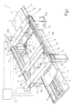
- figure 1 illustrates in perspective and schematically a preferred embodiment of the grinding machine for machining sheets of glass, produced according to the present invention; and
- figure 2 is a plan view, with parts removed for the sake of clarity, of a detail of the machine for grinding in figure 1.
- In figure 1, 1 indicates a grinding machine for
machining sheets 2 of glass (partially illustrated), comprising respectiverectangular perimeter edges 5 to be ground, which have dimensions which can optionally be different from one another. - The machine 1 comprises a
base 8, which supports aconveyor unit 9, which, in particular, comprises a plurality ofdrive belts 10, in order to transfer thesheets 2 in succession one after another, along ahorizontal plane 11, in a longitudinal horizontal straight direction A, from aloading station 12, towards anunloading station 13, through awork station 14. - With reference to figure 2, the
station 14 contains two straightlongitudinal guides 15, which are disposed on opposite sides relative to the direction A, and are integral with thebase 8, and fourbeams beam 20 is connected integrally to thebase 8, in a position adjacent to thestation 13, whereas thebeams guides 15, such as to slide in the direction A, between thebeam 20 and thestation 12, and are actuated by amovement unit 24, which is controlled by an electronic command and control unit 25 (illustrated schematically). - The
unit 24 comprises amotorised shaft 26 and anidle shaft 27, each of which can rotate around its own axis, parallel to the direction B, and at its ends supports two sets of threewheels corresponding shaft wheel 30 to thewheel 32, in order to define ratios of transmission which are different from one another. Theunit 24 also includes two sets of threebelts lateral portions 37 of thebase 8, are each wound around a pair ofwheels respective sections corresponding beam - Each of the
beams suckers 45, which have anupper surface 46 to support thesheet 2 to be ground, constitute part of aretention unit 44, which is controlled by theunit 25, in order to retain thesheet 2 itself on thesurface 46 during grinding, and are connected to a suction pump (not illustrated) by means of respective pneumatic control valves (not illustrated). Eachsucker 45 supports a lower rod, which is connected to a pneumatic cylinder, which is integral with thecorresponding beam unit 25, in order to displace thesuckers 45 between a raised position, in which thesheet 2 is disposed in a position spaced from thebelts 10 in order to be ground, and a lowered rest position, in which thesheet 2 is disposed on thebelts 10, in order to be transferred from and to thestation 14 on theplane 11. - The
station 14 accommodates apositioning unit 50, which is controlled by theunit 25, in order to dispose eachsheet 2 to be processed in a reference position on theplane 11, relative to thebase 8, and comprises a retractable reference stop (not illustrated) of a known type, which is supported by thebase 8, and analignment device 51, which is supported by thelateral portion 37. In particular, thedevice 51 comprises athrust unit 52, which is delimited by asurface 53, parallel to the direction A, and is actuated by anactuator 54, by means of interposition of a four-barchain lever system 55, in order to displace thesurface 53 parallel to itself in the direction B, against one side 5b of thesheet 2, thus aligning the side 5b itself in the direction A. - As illustrated in figure 1, the
station 14 contains aframe 56, which is fixed relative to thebase 8, and comprises aportal 57, which extends along an ideal line of separation of thestations cross-member 58, which faces thebase 8 and is parallel to the direction B. Theframe 56 also comprises twobattens cross-member 58 in thestation 14, constitute part of correspondinglateral portals respective guides - The
frame 56 supports twobridges bridge 63 is interposed between thecross-member 58 and thebridge 64, and which are parallel to thecross-member 58, comprise respectiveopposite end portions 65, which are connected to thebattens guides frame 56, and are controlled by theunit 25, in order to translate thebridges guides - The
cross-member 58 and thebridges respective guides batten 59 comprises aguide 73, parallel to the direction A. There are connected in a sliding manner to theguides respective grinding heads frame 56, and are controlled by theunit 25, in order to displace theheads edge 5, which are transverse relative to one another, and consecutive. - In use, the
sheets 2 are loaded one after another on thestation 12, by setting on theunit 25 the parameters relative to the perimeter dimensions to be obtained for thesheets 2 to be processed. The parameters can be set manually for each of thesheets 2, or they can be entered together with the number ofconsecutive sheets 2 which have the same dimensions, or they can be taken from a data base which is stored and resident in theunit 25, or in a remote computer (not illustrated), which is connected to theunit 25 itself. It is understood that the machine 1 comprises sensors (not illustrated), which allow theunit 25 to detect the type ofsheet 2 present on thestation 14, and check the accuracy of the parameters set. - During transfer of the
sheet 2 to be processed, towards thestation 14, theunit 25 controls actuation of theshaft 26, in order to make thebelts beams sheet 2, keeping thebeams - When the
sheet 2 reaches thestation 14, theunit 25 firstly controls theunit 50, in order to position thesheet 2 in an unambiguous reference position, adjacent to thecross-member 58 and to thebatten 59, and then theunit 44, in order to actuate only thesuckers 45 covered by thesheet 2. Subsequently, theunit 25 actuates theactuators 47 associated with thesuckers 45 which are retaining thesheet 2, such as to bring thesheet 2 itself into the raised machining position. - Whilst these operations are being carried out on the
sheet 2, theunit 25 commands firstly translation of thebridge 64 and of thehead 75 along thecorresponding guides heads bridge 63 along thecorresponding guides sheet 2, and to position theheads edge 5. Simultaneously, the configuration of the grinding wheels of eachhead unit 25, on the basis of the thickness of the sheet ofglass 2 to be ground. - During the grinding operations, the
heads bridge 63 are controlled by theunit 25, such as to be translated simultaneously along thecorresponding guides heads edge 5, following one another without interfering with one another. The point or vertex of completion of machining of eachhead actuators 47 are controlled such as to take thesuckers 45 into their lowered position, and thesuckers 45 themselves are deactivated in order to release thesheet 2, which is then transferred towards thestation 13. Thesubsequent sheet 2 is already on thestation 14, in particular in the case in which thesheet 2 which is being processed is smaller than thestation 14 itself, and is transferred such as to initiate a new cycle on the basis of the parameters entered in theunit 25. - It is apparent from the foregoing that the fact that sides 5a, 5b, 5c, 5d of the
edge 5 which are transverse and/or incident relative to one another are ground at asingle station 14, makes it possible to dispose eachsheet 2 in single reference position or "zero" position for all the grinding operations, thus avoiding displacements of thesheet 2, unlike the situation for the known solutions, in which thesheet 2 must be ground along a first direction, displaced, and ground along a second direction, which is transverse relative to the first. Thus, the machine 1 makes it possible to restrict errors of positioning compared with the known solutions, and to obtain a quality which is substantially unvaried, from one finishedsheet 2 to the next. - As a result of the reduction in the errors of positioning, wear of the grinding wheels is gradual, such that planning of maintenance of the grinding wheels themselves is relatively reliable.
- Compared with the known solutions, the cycle carried out by the machine 1 also has relatively short unproductive times, since, firstly, each
sheet 2 need not be displaced in order to carry out the grinding on the various sides 5a, 5b, 5c, 5d, and, secondly, theheads sheets 2 from and towards thestation 14. The fact that the initial position of theheads successive sheets 2 with dimensions which are different from one another. - Again compared with the known solutions, the machine 1 also has restricted dimensions, since it comprises a
single work station 14, which is disposed along a straight direction A. - The fact that the
sheet 2 to be ground is raised by means of thesuckers 45 enables theheads base 8, and with theoptional suckers 45, or with other devices for positioning thesheets 2, which are located outside of the projection of theedge 5 onto theplane 11. Moreover, theunit 24 makes it possible to adapt the position of thesuckers 45, and to render stable the positioning and retention ofsheets 2 which have dimensions different from one another. - Finally, the structure comprising the
base 8, theframe 56 and thebridges - Finally, it is apparent from the foregoing that modifications and variants can be made to the machine 1 described, which do not depart from the field of protection of the present invention.
- In particular, the machine 1 could comprise only one pair of grinding heads which are disposed on guides or paths which are transverse and/or incident relative to one another, or it can be pre-set in order to grind sheets of glass other than the quadrilateral ones illustrated by way of example.
- In addition, the
units
Claims (14)
- Grinding machine (1) for machining sheets of glass (2) having respective peripheral edges (5) that at least partly require grinding; the machine comprising a support structure (8, 56, 63, 64), a single work station (14) accommodating positioning means (50) for arranging said sheet of glass (2) in an unambiguous reference position on a horizontal plane (11) with respect to said support structure (8, 56, 63, 64), retention means (45) for retaining said sheet of glass (2) in said reference position during grinding, and motorized grinding means (74, 75, 76, 77) for grinding said peripheral edge (5) in said work station (14); characterized in that it also comprises actuator means (47) for vertically displacing said retention means (45) between a raised position for machining said sheet of glass (2) and a lowered rest position.
- Machine according to Claim 1, characterized in that said retention means (45) comprise a plurality of retention members (45) distributed in said plane (11), and in that it also comprises means (25) for controlling said actuator means (47) for moving said retention members (45) vertically independently of each other as a function of the dimensions and shape of said sheet of glass (2) that is to be ground.
- Machine according to Claim 2, characterized in that said actuator means (47) comprise one actuator (47) for each said retention member (45).
- Machine according to any one of Claims 1 to 3, characterized in that said retention means (45) comprise a plurality of retention members (45) and in that it also comprises movement means (24) for varying the relative positions of said retention members (45) in said plane (11).
- Machine according to Claim 4, characterized in that said retention members (45) are disposed in a plurality of parallel rows; said movement means (24) being able to space said rows in a direction of regulation (A) at right-angles to the rows themselves.
- Machine according to Claim 5, characterized in that said means (24) for movement comprise belt transmission means (34, 35, 36).
- Machine according to Claim 6, characterized in that said belt transmission means (34, 35, 36) comprise a plurality of belt transmission units (34, 35, 36), which have transmission ratios which differ from one another, and are each interposed between a corresponding said mobile row, and a single actuation unit (26).
- Machine according to any one of Claims 5 to 7, characterized in that it comprises conveyor means (9) for advancing said sheets of glass (2) on said plane (11) along a direction of advance (A) through said work station (14); said directions of regulation (A) and of advance (A) being parallel to each other.
- Machine according to any one of Claims 1 to 8, characterized in that said grinding means (74, 75, 76, 77) comprise a plurality of independent motorised grinding heads (74, 75, 76, 77); each said grinding head (74, 75, 76, 77) being able, in use, to process a corresponding section (5a, 5b, 5c, 5d) of said perimeter edge (5).
- Machine according to Claim 9, characterized in that it comprises means (25) for command and control, in order to displace said grinding heads (74, 75, 76, 77) in a single direction of advance along said perimeter edge (5).
- Machine according to Claim 10, characterized in that said means (25) for command and control (25) can displace said grinding heads (74, 75, 76, 77) simultaneously along said perimeter edge (5).
- Machine according to any one of Claims 9 to 11, characterized in that said means (61, 62, 70, 71, 72, 73) for guiding comprise first guides (61, 62) (73), which are parallel to one another, and second guides (70) (72) (71), which are parallel to one another and transverse relative to said first guides (61, 62) (73).
- Machine according to Claim 12, characterized in that some of said second guides (71) (72) are mobile in a direction (A), parallel to said first guides (61, 62) (73).
- Machine according to any one of Claims 9 to 13, characterized in that it comprises means (25, 61, 62, 70, 71, 72, 73) for regulation, in order to dispose at least some of said grinding heads (74, 75, 76, 77) in positions for commencement of machining, which differ according to the dimensions of each said sheet of glass (2) to be processed.
Applications Claiming Priority (2)
| Application Number | Priority Date | Filing Date | Title |
|---|---|---|---|
| IT2000TO000663A IT1320224B1 (en) | 2000-06-30 | 2000-06-30 | METHOD AND GRINDING MACHINE FOR THE PROCESSING OF GLASS SHEETS. |
| ITTO000663 | 2000-06-30 |
Publications (2)
| Publication Number | Publication Date |
|---|---|
| EP1166961A1 true EP1166961A1 (en) | 2002-01-02 |
| EP1166961B1 EP1166961B1 (en) | 2003-11-26 |
Family
ID=11457887
Family Applications (2)
| Application Number | Title | Priority Date | Filing Date |
|---|---|---|---|
| EP01114850A Expired - Lifetime EP1175957B1 (en) | 2000-06-30 | 2001-06-28 | Suction table apparatus for supporting and retaining a sheet of glass |
| EP01114851A Expired - Lifetime EP1166961B1 (en) | 2000-06-30 | 2001-06-28 | Grinding machine for simultaneously grinding the four edges of a glass sheet |
Family Applications Before (1)
| Application Number | Title | Priority Date | Filing Date |
|---|---|---|---|
| EP01114850A Expired - Lifetime EP1175957B1 (en) | 2000-06-30 | 2001-06-28 | Suction table apparatus for supporting and retaining a sheet of glass |
Country Status (6)
| Country | Link |
|---|---|
| US (2) | US6604984B2 (en) |
| EP (2) | EP1175957B1 (en) |
| AT (2) | ATE254981T1 (en) |
| DE (2) | DE60101427T2 (en) |
| ES (2) | ES2210067T3 (en) |
| IT (1) | IT1320224B1 (en) |
Cited By (16)
| Publication number | Priority date | Publication date | Assignee | Title |
|---|---|---|---|---|
| WO2010000235A2 (en) | 2008-07-01 | 2010-01-07 | Grenzebach Maschinenbau Gmbh | Method and apparatus for trimming photovoltaic modules |
| CN102114604A (en) * | 2010-12-08 | 2011-07-06 | 江苏扬力数控机床有限公司 | Automatic loading and unloading device of plate processing equipment |
| CN102133725A (en) * | 2010-01-27 | 2011-07-27 | 均豪精密工业股份有限公司 | Improved substrate invalid edge removing system |
| CN102528604A (en) * | 2012-02-08 | 2012-07-04 | 曾钊 | Horizontal type straight line four-side grinding wheel type glass chamfering machine |
| CN103223632A (en) * | 2013-04-15 | 2013-07-31 | 王世强 | Full-automatic four-edge linear refining mill for glass |
| CN104551980A (en) * | 2014-12-26 | 2015-04-29 | 太仓益鑫机床有限公司 | Feeding machine and method for grinder |
| CN105458885A (en) * | 2015-12-24 | 2016-04-06 | 福建省金牛机械发展有限公司 | Unidirectional edge grinding device for multiple obliquely-placed stone slabs |
| ITUA20161572A1 (en) * | 2016-03-11 | 2016-06-11 | Forvet S R L | Machine for processing glass plates and related production process |
| ITUA20161575A1 (en) * | 2016-03-11 | 2016-06-11 | Forvet S R L | Machine for processing glass sheets with a computerized numerical control unit and related production process |
| WO2017154032A1 (en) | 2016-03-11 | 2017-09-14 | Forvet R&D S.R.L. | Machine for working glass slabs with a computerized numeric control assembly and related production process |
| CN108907963A (en) * | 2018-08-13 | 2018-11-30 | 东旭科技集团有限公司 | Cover-plate glass edger unit and cover-plate glass system of processing |
| CN110270897A (en) * | 2019-06-18 | 2019-09-24 | 电子科技大学中山学院 | Circulation grinding device |
| CN110480458A (en) * | 2019-08-21 | 2019-11-22 | 浙江安尚电气有限公司 | A kind of equipment for magnetic core of polishing |
| CN111872809A (en) * | 2020-07-31 | 2020-11-03 | 天津波音复合材料有限责任公司 | Automatic polishing working platform |
| CN112757085A (en) * | 2020-12-31 | 2021-05-07 | 中铁南方工程装备有限公司 | Special-shaped steel plate edge rust removal and grinding device |
| EP3838475A1 (en) * | 2019-12-16 | 2021-06-23 | SCM Group S.p.A. | Improved work bench and machine including this bench |
Families Citing this family (42)
| Publication number | Priority date | Publication date | Assignee | Title |
|---|---|---|---|---|
| KR100832293B1 (en) * | 2002-03-20 | 2008-05-26 | 엘지디스플레이 주식회사 | Grind table of liquid crystal display panel and grinder using it |
| US6869341B2 (en) * | 2002-06-19 | 2005-03-22 | Glassline Corporation | Single-sided finishing apparatus |
| DE10329351A1 (en) * | 2003-06-30 | 2005-01-27 | Rohmer & Stimpfig Maschinen- Und Apparatebau Gmbh | Plant for processing surface elements, in particular of glass |
| WO2005002787A1 (en) | 2003-07-07 | 2005-01-13 | Michael Langenbach | A shaping apparatus |
| ITTO20040724A1 (en) * | 2004-10-19 | 2005-01-19 | Biesse Spa | MACHINE FOR WORKING THE EDGES OF GLASS SLABS, MARBLE, STONE MATERIALS OR CERAMICS IN GENERAL |
| KR101096733B1 (en) * | 2004-12-27 | 2011-12-21 | 엘지디스플레이 주식회사 | cutting equipment of substrate and method for cutting of substrate using the same |
| DE102005027964A1 (en) * | 2005-06-16 | 2006-12-28 | Peter Lisec | Method and device for removing the plastic film supernatant in laminated glass plates |
| US7242623B2 (en) * | 2005-07-12 | 2007-07-10 | Infineon Technologies Flash Gmbh & Co. Kg | Non-volatile memory cell device, programming element and method for programming data into a plurality of non-volatile memory cells |
| ITMI20051851A1 (en) * | 2005-09-30 | 2007-04-01 | Bavelloni Z Spa | TRANSPORT GROUP FOR SLABS ON SLABS MACHINES IN PARTICULAR GLASS SHEETS AND SIMILAR |
| US7294045B1 (en) | 2005-12-21 | 2007-11-13 | Corning Incorporated | Apparatus and method for edge processing of a glass sheet |
| EP2255924A1 (en) * | 2009-05-29 | 2010-12-01 | Mbd S.R.L. | Method for calibrating surfaces of stone material |
| US20110081839A1 (en) * | 2009-10-06 | 2011-04-07 | Apple Inc. | Method and apparatus for polishing a curved edge |
| US20110151753A1 (en) * | 2009-12-22 | 2011-06-23 | Charles Gottschalk | Edge grinding apparatus |
| CN101844323B (en) * | 2010-04-02 | 2012-07-11 | 北京特能设备有限公司 | Horizontal glass straight-line four-side grinding wheel type edge grinding machine |
| EP2433747B1 (en) * | 2010-09-24 | 2013-04-17 | Benteler Maschinenbau GmbH | Method and device for grinding edges of glass boards running parallel to each other |
| CN102139466A (en) * | 2010-12-16 | 2011-08-03 | 尹青 | Glass producing system |
| CN104475870B (en) * | 2014-11-28 | 2017-02-22 | 苏州晟成光伏设备有限公司 | Automatic centering and reversing edge trimmer |
| US9925634B2 (en) | 2015-04-16 | 2018-03-27 | Cardinal Ig Company | Automated seaming apparatus and method |
| CN104889886A (en) * | 2015-05-27 | 2015-09-09 | 安徽精菱玻璃机械有限公司 | Automatic glass edging clamping mechanism |
| PL3313612T3 (en) * | 2015-06-23 | 2020-06-29 | Ancora S.P.A. | Grinding machine for plate-like elements, particularly ceramic tiles and plates, natural stones, glass or similar |
| CN106808341A (en) * | 2015-12-02 | 2017-06-09 | 云南亿能玻璃技术有限公司 | It is a kind of can adjust automatically adsorb dynamics glass processing protection device |
| CN106826567B (en) * | 2015-12-02 | 2019-06-07 | 云南亿能玻璃技术有限公司 | A kind of glass processing system with filtering grinding and adjustment absorption dynamics |
| CN105415235B (en) * | 2015-12-11 | 2017-04-12 | 哈尔滨工程大学 | Self-locking flexible lattice sucker |
| CN106112734A (en) * | 2016-06-22 | 2016-11-16 | 广州智铝铝业有限公司 | Monoblock type metal framework sanding apparatus |
| BE1024342B1 (en) * | 2016-06-30 | 2018-01-29 | Pietro Lopriano | Automatic tile cutters |
| DE102017104246B4 (en) | 2017-03-01 | 2022-09-15 | ARRTSM GmbH | Autonomous production line |
| CN108942592A (en) * | 2017-05-23 | 2018-12-07 | 北京科晶天润玻璃有限公司 | A kind of horizontal membrane removing machine of coated glass |
| CN107322409A (en) * | 2017-06-28 | 2017-11-07 | 陈柯 | A kind of accurately bridge equipment |
| CN107253115A (en) * | 2017-06-28 | 2017-10-17 | 陈柯 | A kind of bridge equipment |
| CN107414667B (en) * | 2017-06-30 | 2019-06-07 | 嘉善中正电子科技有限公司 | A kind of new material grinding device |
| CN107322430B (en) * | 2017-06-30 | 2019-06-07 | 嘉善中正电子科技有限公司 | A kind of multistation grinding device |
| CN108000286A (en) * | 2017-12-07 | 2018-05-08 | 陈海永 | A kind of processing platform structure of agricultural machinery accessory |
| USD870165S1 (en) * | 2018-04-03 | 2019-12-17 | Michael Hacikyan | Glass grinding apparatus |
| CN109129187A (en) * | 2018-11-09 | 2019-01-04 | 昆山上艺电子有限公司 | A kind of mould parts processing and positioning device |
| US11111086B2 (en) | 2019-11-11 | 2021-09-07 | Cardinal Ig Company | Glass stacking systems and methods |
| KR102138080B1 (en) * | 2020-02-13 | 2020-07-27 | (유)다수 | Commonization jig plate |
| CN111283528B (en) * | 2020-03-10 | 2021-02-12 | 浙江新诺贝家居有限公司 | Timber grinding device |
| CN112123187A (en) * | 2020-09-23 | 2020-12-25 | 曾德伟 | Automatic polishing and fluff removing process for inner wall of reed straw |
| CN112123186A (en) * | 2020-09-23 | 2020-12-25 | 曾德伟 | Automatic polishing and fluff removing machine for inner wall of reed straw |
| CN113275973A (en) * | 2020-10-23 | 2021-08-20 | 江苏上玻玻璃有限公司 | Vacuum glass edging and grooving device |
| CN112938364A (en) * | 2020-11-27 | 2021-06-11 | 浙江亚厦装饰股份有限公司 | Translation mechanism |
| CN112677006A (en) * | 2020-12-21 | 2021-04-20 | 刘溪尧 | Color steel plate forming surface treatment system |
Citations (3)
| Publication number | Priority date | Publication date | Assignee | Title |
|---|---|---|---|---|
| US5094282A (en) * | 1990-01-25 | 1992-03-10 | Heian Corporated | Lumber processing apparatus |
| EP0507033A1 (en) * | 1991-04-05 | 1992-10-07 | Manuel Torres Martinez | Machine tool installation for supporting and machining workpieces |
| JPH08197402A (en) * | 1995-01-25 | 1996-08-06 | Mitsuboshi Daiyamondo Kogyo Kk | Polishing method and device for glass substrate |
Family Cites Families (24)
| Publication number | Priority date | Publication date | Assignee | Title |
|---|---|---|---|---|
| CA931024A (en) * | 1970-12-19 | 1973-07-31 | H. Prange Bernard | Method and apparatus for silk screening a pattern on an underlying substrate |
| US3992182A (en) * | 1974-09-18 | 1976-11-16 | Ppg Industries, Inc. | Conveying sheets at non-uniform speed |
| FR2287308A1 (en) * | 1974-10-11 | 1976-05-07 | Intraco | AUTOMATIC LOADING AND UNLOADING DEVICE OF A MACHINE MACHINE |
| US3944461A (en) * | 1974-11-18 | 1976-03-16 | Globe Glass & Trim Company | Machine for laminating glass |
| US4228617A (en) * | 1977-12-31 | 1980-10-21 | Bando Kiko Co., Ltd | Method for grinding glass plates and the like through numerical control and beveling machine therefor |
| JPS5493288A (en) * | 1977-12-31 | 1979-07-24 | Bando Kiko Co | Glass chamfering machine |
| DE3035660C2 (en) * | 1980-09-20 | 1982-10-21 | Flachglas AG, 8510 Fürth | Loading trolley for a system for edge grinding of glass panes |
| US4401204A (en) * | 1981-01-22 | 1983-08-30 | Ppg Industries, Inc. | Assembly system for loading glass sheets of different size on a conveyor |
| US4420361A (en) * | 1981-07-28 | 1983-12-13 | Ppg Industries, Inc. | Apparatus for aligning bent glass sheets for assembly into bent glass sheet sandwiches |
| US4452351A (en) * | 1981-11-23 | 1984-06-05 | Libbey-Owens-Ford Company | Sheet handling apparatus |
| US4493412A (en) * | 1982-06-25 | 1985-01-15 | Ppg Industries, Inc. | Glass sheet positioning apparatus for conveyor platform |
| JPS6130342A (en) * | 1984-07-19 | 1986-02-12 | Nippon Sheet Glass Co Ltd | Profile machining device |
| US4787178A (en) * | 1987-04-13 | 1988-11-29 | Creative Glassworks International, Inc. | Fluid-jet cutting apparatus |
| DE3837471C1 (en) * | 1988-11-04 | 1990-02-01 | Vegla Vereinigte Glaswerke Gmbh, 5100 Aachen, De | |
| JPH0613222Y2 (en) * | 1989-07-31 | 1994-04-06 | セントラル硝子株式会社 | Plate glass positioning device |
| JPH0698563B2 (en) * | 1989-11-30 | 1994-12-07 | 坂東機工株式会社 | Glass plate grinding machine |
| US5173029A (en) * | 1991-07-16 | 1992-12-22 | Toledo Automated Concepts, Inc. | Glass sheet positioning device |
| US5409416A (en) * | 1992-09-01 | 1995-04-25 | Glass Unlimited | Sheet of glass with groove pattern to provide decorative visual effect |
| US5413204A (en) * | 1993-06-25 | 1995-05-09 | Central Glass Co., Ltd. | Glass plate positioning and supplying machine |
| US5411128A (en) * | 1994-01-03 | 1995-05-02 | Vild; Michael J. | Heated glass sheet positioning on roll conveyor |
| US5927469A (en) * | 1996-06-17 | 1999-07-27 | Dunifon; Thomas A. | Method and apparatus for aligning sheets of material moving along a path of travel |
| US6001003A (en) * | 1998-05-11 | 1999-12-14 | Park; Kyung | Wave beveling machine |
| CH694580A5 (en) * | 1999-04-29 | 2005-04-15 | Ip Vitro Vidrio Y Cristal Ltd | Device for machining the edge of a glass sheet. |
| JP3463011B2 (en) | 1999-10-05 | 2003-11-05 | 株式会社平安コーポレーション | Suction table device of NC machine |
-
2000
- 2000-06-30 IT IT2000TO000663A patent/IT1320224B1/en active
-
2001
- 2001-06-28 DE DE60101427T patent/DE60101427T2/en not_active Expired - Lifetime
- 2001-06-28 ES ES01114850T patent/ES2210067T3/en not_active Expired - Lifetime
- 2001-06-28 US US09/894,410 patent/US6604984B2/en not_active Expired - Lifetime
- 2001-06-28 EP EP01114850A patent/EP1175957B1/en not_active Expired - Lifetime
- 2001-06-28 EP EP01114851A patent/EP1166961B1/en not_active Expired - Lifetime
- 2001-06-28 US US09/894,441 patent/US6557689B2/en not_active Expired - Lifetime
- 2001-06-28 AT AT01114851T patent/ATE254981T1/en active
- 2001-06-28 ES ES01114851T patent/ES2210068T3/en not_active Expired - Lifetime
- 2001-06-28 DE DE60101290T patent/DE60101290T2/en not_active Expired - Lifetime
- 2001-06-28 AT AT01114850T patent/ATE255977T1/en active
Patent Citations (3)
| Publication number | Priority date | Publication date | Assignee | Title |
|---|---|---|---|---|
| US5094282A (en) * | 1990-01-25 | 1992-03-10 | Heian Corporated | Lumber processing apparatus |
| EP0507033A1 (en) * | 1991-04-05 | 1992-10-07 | Manuel Torres Martinez | Machine tool installation for supporting and machining workpieces |
| JPH08197402A (en) * | 1995-01-25 | 1996-08-06 | Mitsuboshi Daiyamondo Kogyo Kk | Polishing method and device for glass substrate |
Non-Patent Citations (1)
| Title |
|---|
| PATENT ABSTRACTS OF JAPAN vol. 1996, no. 12 26 December 1996 (1996-12-26) * |
Cited By (25)
| Publication number | Priority date | Publication date | Assignee | Title |
|---|---|---|---|---|
| WO2010000235A3 (en) * | 2008-07-01 | 2011-03-03 | Grenzebach Maschinenbau Gmbh | Method and apparatus for trimming photovoltaic modules |
| KR101202433B1 (en) | 2008-07-01 | 2012-11-16 | 그렌체바흐 마쉬넨바우 게엠베하 | Method and apparatus for trimming photovoltaic modules |
| US10232487B2 (en) | 2008-07-01 | 2019-03-19 | Grenzebach Maschinenbau Gmbh | Method and apparatus for trimming photovoltaic modules |
| CN102216028B (en) * | 2008-07-01 | 2014-08-13 | 格林策巴赫机械制造有限公司 | Method and apparatus for trimming photovoltaic modules |
| WO2010000235A2 (en) | 2008-07-01 | 2010-01-07 | Grenzebach Maschinenbau Gmbh | Method and apparatus for trimming photovoltaic modules |
| CN102133725A (en) * | 2010-01-27 | 2011-07-27 | 均豪精密工业股份有限公司 | Improved substrate invalid edge removing system |
| CN102114604B (en) * | 2010-12-08 | 2015-12-09 | 江苏扬力数控机床有限公司 | A kind of automatic loading and unloading device of sheet processing equipment |
| CN102114604A (en) * | 2010-12-08 | 2011-07-06 | 江苏扬力数控机床有限公司 | Automatic loading and unloading device of plate processing equipment |
| CN102528604A (en) * | 2012-02-08 | 2012-07-04 | 曾钊 | Horizontal type straight line four-side grinding wheel type glass chamfering machine |
| CN102528604B (en) * | 2012-02-08 | 2015-04-22 | 曾钊 | Horizontal type straight line four-side grinding wheel type glass chamfering machine |
| CN103223632A (en) * | 2013-04-15 | 2013-07-31 | 王世强 | Full-automatic four-edge linear refining mill for glass |
| CN104551980A (en) * | 2014-12-26 | 2015-04-29 | 太仓益鑫机床有限公司 | Feeding machine and method for grinder |
| CN105458885A (en) * | 2015-12-24 | 2016-04-06 | 福建省金牛机械发展有限公司 | Unidirectional edge grinding device for multiple obliquely-placed stone slabs |
| ITUA20161572A1 (en) * | 2016-03-11 | 2016-06-11 | Forvet S R L | Machine for processing glass plates and related production process |
| WO2017154032A1 (en) | 2016-03-11 | 2017-09-14 | Forvet R&D S.R.L. | Machine for working glass slabs with a computerized numeric control assembly and related production process |
| CN109070303A (en) * | 2016-03-11 | 2018-12-21 | 福威特研发有限公司 | The machine and related methods of production for being used to process glass plate with computerization numerical control component |
| ITUA20161575A1 (en) * | 2016-03-11 | 2016-06-11 | Forvet S R L | Machine for processing glass sheets with a computerized numerical control unit and related production process |
| US11768475B2 (en) | 2016-03-11 | 2023-09-26 | Forvet S.P.A. Costruzione Macchine Speciali | Machine for working glass slabs with a computerized numeric control assembly and related production process |
| CN108907963A (en) * | 2018-08-13 | 2018-11-30 | 东旭科技集团有限公司 | Cover-plate glass edger unit and cover-plate glass system of processing |
| CN110270897A (en) * | 2019-06-18 | 2019-09-24 | 电子科技大学中山学院 | Circulation grinding device |
| CN110270897B (en) * | 2019-06-18 | 2024-02-06 | 电子科技大学中山学院 | Circulation grinding device |
| CN110480458A (en) * | 2019-08-21 | 2019-11-22 | 浙江安尚电气有限公司 | A kind of equipment for magnetic core of polishing |
| EP3838475A1 (en) * | 2019-12-16 | 2021-06-23 | SCM Group S.p.A. | Improved work bench and machine including this bench |
| CN111872809A (en) * | 2020-07-31 | 2020-11-03 | 天津波音复合材料有限责任公司 | Automatic polishing working platform |
| CN112757085A (en) * | 2020-12-31 | 2021-05-07 | 中铁南方工程装备有限公司 | Special-shaped steel plate edge rust removal and grinding device |
Also Published As
| Publication number | Publication date |
|---|---|
| US6557689B2 (en) | 2003-05-06 |
| ITTO20000663A0 (en) | 2000-06-30 |
| DE60101427T2 (en) | 2004-10-28 |
| US20020046919A1 (en) | 2002-04-25 |
| EP1175957A1 (en) | 2002-01-30 |
| ITTO20000663A1 (en) | 2001-12-30 |
| ES2210067T3 (en) | 2004-07-01 |
| ATE254981T1 (en) | 2003-12-15 |
| DE60101290T2 (en) | 2004-09-09 |
| EP1175957B1 (en) | 2003-12-10 |
| ATE255977T1 (en) | 2003-12-15 |
| US20020061712A1 (en) | 2002-05-23 |
| DE60101427D1 (en) | 2004-01-22 |
| ES2210068T3 (en) | 2004-07-01 |
| EP1166961B1 (en) | 2003-11-26 |
| DE60101290D1 (en) | 2004-01-08 |
| US6604984B2 (en) | 2003-08-12 |
| IT1320224B1 (en) | 2003-11-26 |
Similar Documents
| Publication | Publication Date | Title |
|---|---|---|
| EP1166961B1 (en) | Grinding machine for simultaneously grinding the four edges of a glass sheet | |
| EP1591427B1 (en) | A workstation for machining plates of glass, marble or the like with an automatic system for loading the plates | |
| US7708517B2 (en) | Workpiece transfer method, workpiece transfer system and workpiece transfer device | |
| EP1918067B1 (en) | Flexible assembly for performing work on large surfaces | |
| JP4629731B2 (en) | Work transfer system | |
| US9758311B2 (en) | Method and device for machining large sized plates in a numerical control workstation | |
| US7735817B2 (en) | Device for transporting components for transportation systems | |
| US20110253686A1 (en) | Laser Processing Machines and Methods | |
| US10696487B1 (en) | Pallet conveying apparatus and pallet conveying method | |
| EP2492068A1 (en) | Cutting apparatus | |
| KR101465283B1 (en) | Centring device for flat workpieces in a press and method for adjusting such a centring device | |
| KR20120022587A (en) | Manufacturing device and method of plate-like body and edge face grinding device and method of plate-like body | |
| WO2013118175A1 (en) | Machining system and control method | |
| KR100977870B1 (en) | Transfer robot | |
| EP1840053B1 (en) | Workpiece transfer method, system and device | |
| US20030015001A1 (en) | Method of setting a machine for machining a sheet of glass, and machine configurable thereby | |
| CN217322395U (en) | Positioning and conveying device | |
| CN112041136A (en) | Sheet metal processing system, method for operating a sheet metal processing system, and control and/or regulating device | |
| EP4257319A1 (en) | Numerical-control work centre for machining plates of glass or plates of natural or synthetic stone material, and corresponding machining method | |
| EP4275836A1 (en) | Workpiece processing machine of variable size and shape such as beams, slabs, panels and the like, in particular in wood or the like | |
| US20240165754A1 (en) | A System and a Method for Locating a Workpiece-Holder Frame in Position in a Processing or Assembling Station of a Production Plant | |
| JPS6117808Y2 (en) | ||
| EP4257317A1 (en) | Numerical-control work centre for machining plates of glass or plates of natural or synthetic stone material with machining head having an auxiliary plate-supporting unit, and machining method | |
| KR20160103247A (en) | Press High Speed Operating System | |
| JPH06277975A (en) | Work moving carrying mechanism |
Legal Events
| Date | Code | Title | Description |
|---|---|---|---|
| PUAI | Public reference made under article 153(3) epc to a published international application that has entered the european phase |
Free format text: ORIGINAL CODE: 0009012 |
|
| AK | Designated contracting states |
Kind code of ref document: A1 Designated state(s): AT BE CH CY DE DK ES FI FR GB GR IE IT LI LU MC NL PT SE TR |
|
| AX | Request for extension of the european patent |
Free format text: AL;LT;LV;MK;RO;SI |
|
| 17P | Request for examination filed |
Effective date: 20020701 |
|
| AKX | Designation fees paid |
Free format text: AT BE CH CY DE DK ES FI FR GB GR IE IT LI LU MC NL PT SE TR |
|
| 17Q | First examination report despatched |
Effective date: 20030124 |
|
| GRAH | Despatch of communication of intention to grant a patent |
Free format text: ORIGINAL CODE: EPIDOS IGRA |
|
| GRAS | Grant fee paid |
Free format text: ORIGINAL CODE: EPIDOSNIGR3 |
|
| GRAA | (expected) grant |
Free format text: ORIGINAL CODE: 0009210 |
|
| AK | Designated contracting states |
Kind code of ref document: B1 Designated state(s): AT BE CH CY DE DK ES FI FR GB GR IE IT LI LU MC NL PT SE TR |
|
| PG25 | Lapsed in a contracting state [announced via postgrant information from national office to epo] |
Ref country code: NL Free format text: LAPSE BECAUSE OF FAILURE TO SUBMIT A TRANSLATION OF THE DESCRIPTION OR TO PAY THE FEE WITHIN THE PRESCRIBED TIME-LIMIT Effective date: 20031126 Ref country code: TR Free format text: LAPSE BECAUSE OF FAILURE TO SUBMIT A TRANSLATION OF THE DESCRIPTION OR TO PAY THE FEE WITHIN THE PRESCRIBED TIME-LIMIT Effective date: 20031126 Ref country code: BE Free format text: LAPSE BECAUSE OF FAILURE TO SUBMIT A TRANSLATION OF THE DESCRIPTION OR TO PAY THE FEE WITHIN THE PRESCRIBED TIME-LIMIT Effective date: 20031126 Ref country code: FI Free format text: LAPSE BECAUSE OF FAILURE TO SUBMIT A TRANSLATION OF THE DESCRIPTION OR TO PAY THE FEE WITHIN THE PRESCRIBED TIME-LIMIT Effective date: 20031126 Ref country code: CY Free format text: LAPSE BECAUSE OF FAILURE TO SUBMIT A TRANSLATION OF THE DESCRIPTION OR TO PAY THE FEE WITHIN THE PRESCRIBED TIME-LIMIT Effective date: 20031126 |
|
| REG | Reference to a national code |
Ref country code: GB Ref legal event code: FG4D |
|
| REG | Reference to a national code |
Ref country code: CH Ref legal event code: EP |
|
| REF | Corresponds to: |
Ref document number: 60101290 Country of ref document: DE Date of ref document: 20040108 Kind code of ref document: P |
|
| REG | Reference to a national code |
Ref country code: IE Ref legal event code: FG4D |
|
| REG | Reference to a national code |
Ref country code: CH Ref legal event code: NV Representative=s name: ISLER & PEDRAZZINI AG |
|
| PG25 | Lapsed in a contracting state [announced via postgrant information from national office to epo] |
Ref country code: DK Free format text: LAPSE BECAUSE OF FAILURE TO SUBMIT A TRANSLATION OF THE DESCRIPTION OR TO PAY THE FEE WITHIN THE PRESCRIBED TIME-LIMIT Effective date: 20040226 Ref country code: GR Free format text: LAPSE BECAUSE OF FAILURE TO SUBMIT A TRANSLATION OF THE DESCRIPTION OR TO PAY THE FEE WITHIN THE PRESCRIBED TIME-LIMIT Effective date: 20040226 Ref country code: SE Free format text: LAPSE BECAUSE OF FAILURE TO SUBMIT A TRANSLATION OF THE DESCRIPTION OR TO PAY THE FEE WITHIN THE PRESCRIBED TIME-LIMIT Effective date: 20040226 |
|
| NLV1 | Nl: lapsed or annulled due to failure to fulfill the requirements of art. 29p and 29m of the patents act | ||
| PG25 | Lapsed in a contracting state [announced via postgrant information from national office to epo] |
Ref country code: IE Free format text: LAPSE BECAUSE OF NON-PAYMENT OF DUE FEES Effective date: 20040628 Ref country code: LU Free format text: LAPSE BECAUSE OF NON-PAYMENT OF DUE FEES Effective date: 20040628 |
|
| PG25 | Lapsed in a contracting state [announced via postgrant information from national office to epo] |
Ref country code: MC Free format text: LAPSE BECAUSE OF NON-PAYMENT OF DUE FEES Effective date: 20040630 |
|
| REG | Reference to a national code |
Ref country code: ES Ref legal event code: FG2A Ref document number: 2210068 Country of ref document: ES Kind code of ref document: T3 |
|
| ET | Fr: translation filed | ||
| PLBE | No opposition filed within time limit |
Free format text: ORIGINAL CODE: 0009261 |
|
| STAA | Information on the status of an ep patent application or granted ep patent |
Free format text: STATUS: NO OPPOSITION FILED WITHIN TIME LIMIT |
|
| 26N | No opposition filed |
Effective date: 20040827 |
|
| REG | Reference to a national code |
Ref country code: IE Ref legal event code: MM4A |
|
| REG | Reference to a national code |
Ref country code: CH Ref legal event code: PCAR Free format text: ISLER & PEDRAZZINI AG;POSTFACH 1772;8027 ZUERICH (CH) |
|
| PG25 | Lapsed in a contracting state [announced via postgrant information from national office to epo] |
Ref country code: PT Free format text: LAPSE BECAUSE OF NON-PAYMENT OF DUE FEES Effective date: 20040426 |
|
| PG25 | Lapsed in a contracting state [announced via postgrant information from national office to epo] |
Ref country code: IT Free format text: LAPSE BECAUSE OF NON-PAYMENT OF DUE FEES Effective date: 20100628 |
|
| PGRI | Patent reinstated in contracting state [announced from national office to epo] |
Ref country code: IT Effective date: 20110616 |
|
| REG | Reference to a national code |
Ref country code: FR Ref legal event code: PLFP Year of fee payment: 16 |
|
| REG | Reference to a national code |
Ref country code: DE Ref legal event code: R081 Ref document number: 60101290 Country of ref document: DE Owner name: FORVET R&D S.R.L., IT Free format text: FORMER OWNER: FORVET S.R.L., VOLVERA, IT Ref country code: DE Ref legal event code: R082 Ref document number: 60101290 Country of ref document: DE Representative=s name: PATENTANWAELTE CANZLER & BERGMEIER PARTNERSCHA, DE |
|
| REG | Reference to a national code |
Ref country code: CH Ref legal event code: PFA Owner name: FORVET S.P.A., IT Free format text: FORMER OWNER: FORVET S.R.L., IT Ref country code: CH Ref legal event code: PUE Owner name: FORVET R&D S.R.L., IT Free format text: FORMER OWNER: FORVET S.P.A., IT |
|
| REG | Reference to a national code |
Ref country code: AT Ref legal event code: PC Ref document number: 254981 Country of ref document: AT Kind code of ref document: T Owner name: FORVET R&D S.R.L., IT Effective date: 20170124 |
|
| REG | Reference to a national code |
Ref country code: FR Ref legal event code: PLFP Year of fee payment: 17 |
|
| REG | Reference to a national code |
Ref country code: GB Ref legal event code: 732E Free format text: REGISTERED BETWEEN 20170622 AND 20170628 |
|
| REG | Reference to a national code |
Ref country code: ES Ref legal event code: PC2A Owner name: FORVET R&D S.R.L. FORVET R&D S.R.L. Effective date: 20170824 |
|
| REG | Reference to a national code |
Ref country code: FR Ref legal event code: TP Owner name: FORVET RESEARCH & DEVELOPMENT S.R.L, IT Effective date: 20170821 |
|
| REG | Reference to a national code |
Ref country code: FR Ref legal event code: PLFP Year of fee payment: 18 |
|
| PGFP | Annual fee paid to national office [announced via postgrant information from national office to epo] |
Ref country code: DE Payment date: 20200623 Year of fee payment: 20 Ref country code: FR Payment date: 20200625 Year of fee payment: 20 |
|
| PGFP | Annual fee paid to national office [announced via postgrant information from national office to epo] |
Ref country code: IT Payment date: 20200612 Year of fee payment: 20 Ref country code: GB Payment date: 20200629 Year of fee payment: 20 |
|
| PGFP | Annual fee paid to national office [announced via postgrant information from national office to epo] |
Ref country code: AT Payment date: 20200619 Year of fee payment: 20 |
|
| PGFP | Annual fee paid to national office [announced via postgrant information from national office to epo] |
Ref country code: ES Payment date: 20200701 Year of fee payment: 20 |
|
| PGFP | Annual fee paid to national office [announced via postgrant information from national office to epo] |
Ref country code: CH Payment date: 20200702 Year of fee payment: 20 |
|
| REG | Reference to a national code |
Ref country code: DE Ref legal event code: R071 Ref document number: 60101290 Country of ref document: DE |
|
| REG | Reference to a national code |
Ref country code: GB Ref legal event code: PE20 Expiry date: 20210627 |
|
| REG | Reference to a national code |
Ref country code: AT Ref legal event code: MK07 Ref document number: 254981 Country of ref document: AT Kind code of ref document: T Effective date: 20210628 |
|
| PG25 | Lapsed in a contracting state [announced via postgrant information from national office to epo] |
Ref country code: GB Free format text: LAPSE BECAUSE OF EXPIRATION OF PROTECTION Effective date: 20210627 |
|
| REG | Reference to a national code |
Ref country code: ES Ref legal event code: FD2A Effective date: 20211026 |
|
| PG25 | Lapsed in a contracting state [announced via postgrant information from national office to epo] |
Ref country code: ES Free format text: LAPSE BECAUSE OF EXPIRATION OF PROTECTION Effective date: 20210629 |