EP1165926B1 - Factory gate - Google Patents
Factory gate Download PDFInfo
- Publication number
- EP1165926B1 EP1165926B1 EP00929326A EP00929326A EP1165926B1 EP 1165926 B1 EP1165926 B1 EP 1165926B1 EP 00929326 A EP00929326 A EP 00929326A EP 00929326 A EP00929326 A EP 00929326A EP 1165926 B1 EP1165926 B1 EP 1165926B1
- Authority
- EP
- European Patent Office
- Prior art keywords
- slats
- gate
- segments
- spiral
- accordance
- Prior art date
- Legal status (The legal status is an assumption and is not a legal conclusion. Google has not performed a legal analysis and makes no representation as to the accuracy of the status listed.)
- Expired - Lifetime
Links
- 239000000463 material Substances 0.000 claims abstract description 34
- 238000013461 design Methods 0.000 claims description 13
- 229920003229 poly(methyl methacrylate) Polymers 0.000 claims description 5
- 239000004926 polymethyl methacrylate Substances 0.000 claims description 5
- 229920002994 synthetic fiber Polymers 0.000 claims 1
- 238000005265 energy consumption Methods 0.000 abstract description 6
- 241000446313 Lamella Species 0.000 description 27
- 238000005452 bending Methods 0.000 description 22
- 238000004804 winding Methods 0.000 description 18
- 229910052782 aluminium Inorganic materials 0.000 description 9
- XAGFODPZIPBFFR-UHFFFAOYSA-N aluminium Chemical compound [Al] XAGFODPZIPBFFR-UHFFFAOYSA-N 0.000 description 9
- 239000004033 plastic Substances 0.000 description 7
- 229920003023 plastic Polymers 0.000 description 7
- 230000003068 static effect Effects 0.000 description 5
- 238000010586 diagram Methods 0.000 description 4
- 238000004519 manufacturing process Methods 0.000 description 4
- 238000012360 testing method Methods 0.000 description 4
- 230000001133 acceleration Effects 0.000 description 3
- 238000010276 construction Methods 0.000 description 3
- 238000011161 development Methods 0.000 description 3
- 230000018109 developmental process Effects 0.000 description 3
- 229910052751 metal Inorganic materials 0.000 description 3
- 239000002184 metal Substances 0.000 description 3
- 229910000831 Steel Inorganic materials 0.000 description 2
- 230000015572 biosynthetic process Effects 0.000 description 2
- 238000009434 installation Methods 0.000 description 2
- 239000004417 polycarbonate Substances 0.000 description 2
- 239000010959 steel Substances 0.000 description 2
- 238000012549 training Methods 0.000 description 2
- 206010038743 Restlessness Diseases 0.000 description 1
- 235000004443 Ricinus communis Nutrition 0.000 description 1
- 240000000528 Ricinus communis Species 0.000 description 1
- 230000006978 adaptation Effects 0.000 description 1
- 230000002411 adverse Effects 0.000 description 1
- 238000013459 approach Methods 0.000 description 1
- 230000001419 dependent effect Effects 0.000 description 1
- 230000000694 effects Effects 0.000 description 1
- 238000005516 engineering process Methods 0.000 description 1
- 238000002474 experimental method Methods 0.000 description 1
- 230000009191 jumping Effects 0.000 description 1
- 150000002739 metals Chemical class 0.000 description 1
- 230000035515 penetration Effects 0.000 description 1
- 239000012994 photoredox catalyst Substances 0.000 description 1
- 229920000515 polycarbonate Polymers 0.000 description 1
- 239000004800 polyvinyl chloride Substances 0.000 description 1
- 230000000284 resting effect Effects 0.000 description 1
- 238000007789 sealing Methods 0.000 description 1
- 238000006467 substitution reaction Methods 0.000 description 1
- 239000013585 weight reducing agent Substances 0.000 description 1
Images


Classifications
-
- E—FIXED CONSTRUCTIONS
- E06—DOORS, WINDOWS, SHUTTERS, OR ROLLER BLINDS IN GENERAL; LADDERS
- E06B—FIXED OR MOVABLE CLOSURES FOR OPENINGS IN BUILDINGS, VEHICLES, FENCES OR LIKE ENCLOSURES IN GENERAL, e.g. DOORS, WINDOWS, BLINDS, GATES
- E06B9/00—Screening or protective devices for wall or similar openings, with or without operating or securing mechanisms; Closures of similar construction
- E06B9/02—Shutters, movable grilles, or other safety closing devices, e.g. against burglary
- E06B9/08—Roll-type closures
-
- E—FIXED CONSTRUCTIONS
- E06—DOORS, WINDOWS, SHUTTERS, OR ROLLER BLINDS IN GENERAL; LADDERS
- E06B—FIXED OR MOVABLE CLOSURES FOR OPENINGS IN BUILDINGS, VEHICLES, FENCES OR LIKE ENCLOSURES IN GENERAL, e.g. DOORS, WINDOWS, BLINDS, GATES
- E06B9/00—Screening or protective devices for wall or similar openings, with or without operating or securing mechanisms; Closures of similar construction
- E06B9/02—Shutters, movable grilles, or other safety closing devices, e.g. against burglary
- E06B9/06—Shutters, movable grilles, or other safety closing devices, e.g. against burglary collapsible or foldable, e.g. of the bellows or lazy-tongs type
- E06B9/0607—Shutters, movable grilles, or other safety closing devices, e.g. against burglary collapsible or foldable, e.g. of the bellows or lazy-tongs type comprising a plurality of similar rigid closing elements movable to a storage position
- E06B9/0615—Shutters, movable grilles, or other safety closing devices, e.g. against burglary collapsible or foldable, e.g. of the bellows or lazy-tongs type comprising a plurality of similar rigid closing elements movable to a storage position characterised by the closing elements
- E06B9/0638—Slats or panels
-
- E—FIXED CONSTRUCTIONS
- E06—DOORS, WINDOWS, SHUTTERS, OR ROLLER BLINDS IN GENERAL; LADDERS
- E06B—FIXED OR MOVABLE CLOSURES FOR OPENINGS IN BUILDINGS, VEHICLES, FENCES OR LIKE ENCLOSURES IN GENERAL, e.g. DOORS, WINDOWS, BLINDS, GATES
- E06B9/00—Screening or protective devices for wall or similar openings, with or without operating or securing mechanisms; Closures of similar construction
- E06B9/02—Shutters, movable grilles, or other safety closing devices, e.g. against burglary
- E06B9/08—Roll-type closures
- E06B9/11—Roller shutters
- E06B9/15—Roller shutters with closing members formed of slats or the like
-
- E—FIXED CONSTRUCTIONS
- E06—DOORS, WINDOWS, SHUTTERS, OR ROLLER BLINDS IN GENERAL; LADDERS
- E06B—FIXED OR MOVABLE CLOSURES FOR OPENINGS IN BUILDINGS, VEHICLES, FENCES OR LIKE ENCLOSURES IN GENERAL, e.g. DOORS, WINDOWS, BLINDS, GATES
- E06B9/00—Screening or protective devices for wall or similar openings, with or without operating or securing mechanisms; Closures of similar construction
- E06B9/56—Operating, guiding or securing devices or arrangements for roll-type closures; Spring drums; Tape drums; Counterweighting arrangements therefor
- E06B9/58—Guiding devices
-
- E—FIXED CONSTRUCTIONS
- E06—DOORS, WINDOWS, SHUTTERS, OR ROLLER BLINDS IN GENERAL; LADDERS
- E06B—FIXED OR MOVABLE CLOSURES FOR OPENINGS IN BUILDINGS, VEHICLES, FENCES OR LIKE ENCLOSURES IN GENERAL, e.g. DOORS, WINDOWS, BLINDS, GATES
- E06B9/00—Screening or protective devices for wall or similar openings, with or without operating or securing mechanisms; Closures of similar construction
- E06B9/02—Shutters, movable grilles, or other safety closing devices, e.g. against burglary
- E06B9/06—Shutters, movable grilles, or other safety closing devices, e.g. against burglary collapsible or foldable, e.g. of the bellows or lazy-tongs type
- E06B9/0607—Shutters, movable grilles, or other safety closing devices, e.g. against burglary collapsible or foldable, e.g. of the bellows or lazy-tongs type comprising a plurality of similar rigid closing elements movable to a storage position
- E06B9/0646—Shutters, movable grilles, or other safety closing devices, e.g. against burglary collapsible or foldable, e.g. of the bellows or lazy-tongs type comprising a plurality of similar rigid closing elements movable to a storage position characterised by the relative arrangement of the closing elements in the stored position
- E06B2009/0684—Shutters, movable grilles, or other safety closing devices, e.g. against burglary collapsible or foldable, e.g. of the bellows or lazy-tongs type comprising a plurality of similar rigid closing elements movable to a storage position characterised by the relative arrangement of the closing elements in the stored position stored in a spiral like arrangement
-
- E—FIXED CONSTRUCTIONS
- E06—DOORS, WINDOWS, SHUTTERS, OR ROLLER BLINDS IN GENERAL; LADDERS
- E06B—FIXED OR MOVABLE CLOSURES FOR OPENINGS IN BUILDINGS, VEHICLES, FENCES OR LIKE ENCLOSURES IN GENERAL, e.g. DOORS, WINDOWS, BLINDS, GATES
- E06B9/00—Screening or protective devices for wall or similar openings, with or without operating or securing mechanisms; Closures of similar construction
- E06B9/02—Shutters, movable grilles, or other safety closing devices, e.g. against burglary
- E06B9/08—Roll-type closures
- E06B9/11—Roller shutters
- E06B9/15—Roller shutters with closing members formed of slats or the like
- E06B2009/1577—Slat end pieces used for guiding shutter
- E06B2009/1588—Slat end pieces used for guiding shutter inserted in engaging section of adjacent slats
Definitions
- the invention is based on a fast-moving Industrial door according to the preamble of claim 1.
- roller shutters are generally known the roller shutter principle with a curtain made of slats and upper winding shaft are formed. These roller shutters are suitable as external seals for buildings e.g. while Business interruptions, but are during the Operating normally held in the open position because Openings and closing movements due to the very slow runs take a lot of time.
- the turns of the door leaf or curtain are as here conventional roller doors in the winding on top of each other, so that they scratch and dirty accordingly, what should be avoided.
- the curtain made of thick soft plastic is with its side edges in the wall Guides held and at its bottom with a transversal aluminum sign with attached below Rubber contact strip completed.
- the margins of the curtain are replaced by buttons in the wind held vertical guides from which the curtain otherwise it could slip out. Larger wind forces lead due to the stretching of the bulge material in the Middle area of the curtain, with the wind protection buttons the vertical guides of the gate opening being able to leave. Reintroducing the wind safety buttons is usually problematic, and damage to the curtain can occur.
- the slats of the Door leaf made of a light, relatively soft elastic and yet tensile and resistant material to manufacture.
- the tensile strength and durability serves on the one hand to secure the breakthrough Gate opening in times of business interruption and on the other hand, the damage-free inclusion of Wind loads.
- the slats are in an arch shape in the transverse direction to the gate opening and are through the wind forces on train.
- the invention is based on the object high-speed industrial door of the generic type so to design that on the one hand the susceptibility to damage drastically when starting unintentionally lowered and on the other hand without impermissibly high Development of noise at high speeds can be.
- GB 1,172,560 A So from GB 1,172,560 A is a blind or a roller shutter made of interconnected slats known which, for example, for the completion of Escalator access, but also from building openings can be used.
- the slats of this well-known Roller shutters engage in side guides and point rollers on the inside of the guide rails.
- the Known roller shutters can be operated manually or mechanically be driven, in the latter case a Sprocket attacks on the rollers of the blinds and further promotes this tooth gap for tooth gap.
- Form the guides in the spiral section can be in any Be adapted to the respective installation conditions, so that depending on the installation, elongated spiral sections with straight sections or compact building spiral sections with almost continuously curved Result in spiral shape.
- the material of the slats is also freely adapt to the respective application, as in With regard to the low even with mechanical drive No dynamic forces act on the running speed and because of the usually small Slat width also a subordinate to static forces Ro
- DE 37 09 884 A1 is an industrial door known in the form of a spiral door with lamellar armor, which in the open position in a spiral section with a continuously curved spiral shape and non-contact The arrangement of the slats is present. This is what it is about However, it is a sliding spiral door with a wall side standing changing areas and rigid slats. The Problem of bending the slats under weight does not occur because of the lamellar armor one of its sides is hanging. For this The reason is a mutual distance between the guides in the Spiral section to avoid mutual contact not necessary if the slats are bent. As a result of the rigid design of the slats no impermissible even under dynamic loads Deformations.
- the bending stiffness of less than 1500 Nm 2 provided according to the invention for the lamella made of flexible material is defined as the product of the elasticity module E and the area moment of inertia I, E being a characteristic value for the material used and I a characteristic value for the geometric configuration of the lamella.
- the desired bending stiffness can thus be provided by skillful setting of these parameters, which enables adaptation to different door widths, preconditions with regard to the material, for example with regard to impact resistance, etc.
- bending stiffnesses below the above-mentioned limit are particularly suitable for the object of the invention, that is to say that they can achieve advantageous effects in conjunction with the continuously curved spiral shape, as explained above.
- the geometrical shape is also predetermined to a certain extent, this condition also means that the material used has a modulus of elasticity which allows the door leaf to be less susceptible to damage from external influences.
- the invention thus creates for the first time High-speed spiral door with a door leaf in the form of a Lamellar armor, which is greatly increased by another Running speed and low susceptibility to damage with extremely low noise and low energy Operation as a significantly improved gate closure between Vehicle passage is suitable, but still in times of business interruption as a full, Hermetic and breakthrough proof closure of the Gate opening can serve.
- lamellae made of a material with a bending stiffness of less than 1000 N ⁇ m 2 , preferably less than 500 N ⁇ m 2 and in particular less than 200 N ⁇ m 2
- materials with an even lower modulus of elasticity e.g. B. less than 40,000 N / mm 2 and in particular less than 10,000 N / mm 2
- slats of this type are further characterized in that, together with the continuously curved spiral shape, they show improved dynamic properties.
- the behavior of the door leaf can be specifically adjusted with the specified bending stiffness.
- the choice of material according to the invention for the lamellae with a density of 2 2 g / cm 3 enables a significant reduction in the moving masses, as a result of which the centrifugal forces can be significantly reduced.
- the slats then have a relatively low weight, which means that the deflection of the slats in the upper winding is less even in the idle state. Therefore, the guide rails can be arranged even closer to each other. This enables a further reduction in the space required in the lintel.
- the slats are transparent. So that will it is possible to leave the space behind the gate opening even when closed To see the gate, e.g. any Oncoming traffic can be perceived. Because the slats according to the invention are present in the wrap without contact, can also scratch the lamella surfaces in the be excluded essentially, whereby the Transparency is permanently maintained.
- a Industrial door 1 a door leaf covering the door opening on which of a variety of bendable with each other connected slats 2 is formed.
- the slats 2 are horizontal over the gate opening arranged in a gradient and on their side edges hinged together 3 hinged together.
- the hinge members of each hinge strap 3 are about not shown in more detail here Hinge pin bendable against each other.
- caster wheels 4 coaxial to the Hinge pins arranged and engage in guides 5 one, which both sides of the gate opening in frames 6 are arranged.
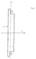
- Each of the guides 5 has a vertical section 51 in the area of the frame 6 of the door opening and one Spiral section 52 in the lintel area of the gate opening, as best seen in Fig. 1. That from the Variety of slats 2 formed door leaf is at open gate 1, as shown in Fig. 1, in the spiral section 52 of the guide 5 retracted.
- the Gate 1 is driven via a here engine, not shown.
- the slats 2 of the door leaf are in the spiral section 52 in front of each other. Further the slats 2 engage at least in the spiral section 52 not in the guides 5.
- the spiral section 52 points approximately a continuously curved spiral shape, which without a straight line Parts or turning points is formed.
- the spiral section 52 points approximately a continuously curved spiral shape, which without a straight line Parts or turning points is formed.
- the winding area therefore takes place under the same direction and preferably essentially constant in amount, at least no abrupt fluctuations subject to centrifugal forces.
- a possible bulge of the individual slats 2 under the influence of centrifugal forces in the area between the guides 5 is also harmless, since the external slat due to the larger radius stronger than the inner one Lamella 2 is acted upon by the centrifugal force.
- a mutual contact of the slats 2 can therefore both Avoided in the resting as well as in the moving state become.
- a single-walled lamella 2 is shown in cross-section. It consists of a material with a low modulus of elasticity, preferably PMMA or PVC or a combination of both. End sections 21 of the lamella 2 on both sides also serve to accommodate the rubber strips, not shown here, by means of which the individual lamellae 2 are connected to one another in a sealing but angled manner. Each slat 2 also has through holes, not shown, by means of which it is mounted on the hinge 3.
- This single-walled lamella 2 has an area moment of inertia I y of 22000 mm 4 .
- a double-walled lamella 2 is shown in FIG. 6. In terms of its functional dimensions, this is designed in accordance with the single-walled lamella 2 and can be exchanged for this. It has an area moment of inertia I y of 35800 mm 4 .
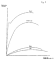
- the characteristic curve a) stands for a single-walled lamella with a Length of 3000 mm, while the characteristic curve b) a describes double-walled lamella of this length.
- the Characteristic curve c) stands for a single-walled lamella a length of 6000 mm, while the characteristic curve d) a describes double-walled lamella of this length.
- the bending stiffness is therefore a measure of both the material used and the geometry of the lamella, whereby the following applies: e * I y ⁇ l 3
- the bending stiffness changes in the third power to a change in the length of the rod or the lamella.
- Practical tests have shown that a bending stiffness of approx. 1500 N ⁇ m 2 is suitable for all common door widths up to 8 m and is particularly advantageous in combination with the continuously curved spiral shape.
- each Gate width can therefore be seen from this context derive and can also be essential with small door widths be less.
- Other design factors the bending stiffness result from the certain Dimensions given design of the slat shape and the desired insensitivity to external influences such as. an unintentional start-up, i.e. the Modulus of elasticity of the material.
- the bending stiffness of less than 1500 Nm 2 provided according to the invention can therefore be achieved with different materials and geometries, depending on the door width.
- the lamella can also be made of aluminum with a corresponding geometric design, but this material is disadvantageous with regard to the lower elastic deformability in comparison to the plastics.
- the modulus of elasticity is a function of the tension for elastic stretching and accordingly only meaningful in the elastic range having. Because with metals the voltage is different Elasticity limit with much lower strains is reached, billiards etc. lead to faster permanent deformations on the lamella or on Door leaf. In the design of the slats consequently the range of elastic stretching of the respective one Material.
- each lamella 2 can also be made transparent be a single-walled design of the slat 2 also advantageous in terms of an improved Is transparency. Furthermore, only individual Slats 2 of the door leaf are transparent become.
- the Slats not directly guided in the guides 5, but only by means of the rollers 4.
- the invention thus creates a high-speed industrial door 1 in which the guides 5 have a spiral section 52 with a continuously curved spiral shape.
- the door leaf of the industrial door 1 has slats 2 which are made of a material with a bending stiffness of less than 1500 Nm 2 .
- slats 2 which are made of a material with a bending stiffness of less than 1500 Nm 2 .
- Due to the flexible design of the slats 2 forces can also be absorbed elastically transversely to the door opening plane, so that permanent deformations of the door leaf are avoided to a certain extent when starting.
Landscapes
- Engineering & Computer Science (AREA)
- Structural Engineering (AREA)
- Architecture (AREA)
- Civil Engineering (AREA)
- Operating, Guiding And Securing Of Roll- Type Closing Members (AREA)
- Gates (AREA)
- Thyristors (AREA)
- Crystals, And After-Treatments Of Crystals (AREA)
- Transition And Organic Metals Composition Catalysts For Addition Polymerization (AREA)
Abstract
Description
Die Erfindung geht von einem schnellaufenden
Industrietor nach dem Oberbegriff des Anspruchs 1 aus.The invention is based on a fast-moving
Industrial door according to the preamble of
Allgemein bekannt sind übliche Rolltore, die nach dem Rolladenprinzip mit einem Behang aus Lamellen und oberer Wickelwelle ausgebildet sind. Diese Rolltore eignen sich als Außenabschluß für Bauwerke z.B. während Betriebsunterbrechungen, werden aber während des Betriebs normalerweise in Öffnungsstellung gehalten, da Öffnungen und Schließbewegungen aufgrund des sehr langsamen Laufs viel Zeit benötigen.Common roller shutters are generally known the roller shutter principle with a curtain made of slats and upper winding shaft are formed. These roller shutters are suitable as external seals for buildings e.g. while Business interruptions, but are during the Operating normally held in the open position because Openings and closing movements due to the very slow runs take a lot of time.
Aus der Praxis sind auch Schnellauf-Rolltore mit: Wicklung des Torblatts oberhalb der Toröffnung bekannt. Hierbei handelt es sich z.B. um Weich-PVC-Tore, bei denen ein Behang aus Weich-PVC oder einem ähnlichen weichen Kunststoff auf einer Wickelwelle in der üblichen Weise aufgewickelt ist und für den Abschluß der Toröffnung abgewickelt werden kann. Die Windungen des Torblatts bzw. Torbehangs liegen hier wie bei konventionellen Rolltoren in der Wicklung aufeinander, so daß sie entsprechend verkratzen und verschmutzen, was vermieden werden soll. Der Behang aus dickem Weich-Kunststoff ist mit seinen Seitenrändern in wandseitigen Führungen gehalten und an seiner Unterseite mit einem querverlaufenden Aluminiumschild mit darunter befestigter Gummi-Kontaktleiste abgeschlossen. Die Seitenränder des Behanges werden bei Windkräften durch Knöpfe in den vertikalen Führungen gehalten, aus denen der Behang sonst herausrutschen könnte. Größere Windkräfte führen aufgrund der Dehnung des Materials zum Ausbeulen im Mittelbereich des Behanges, wobei die Windsicherungsknöpfe dabei die vertikalen Führungen der Toröffnung verlassen können. Das Wiedereinführen der Windsicherungsknöpfe gestaltet sich dabei in der Regel problematisch, und es können Beschädigungen am Behang auftreten.High-speed roller doors with: Known winding of the door leaf above the door opening. This is e.g. for soft PVC gates, at which a curtain made of soft PVC or a similar soft plastic on a winding shaft in the usual way is wound up and for completion the gate opening can be handled. The turns of the door leaf or curtain are as here conventional roller doors in the winding on top of each other, so that they scratch and dirty accordingly, what should be avoided. The curtain made of thick soft plastic is with its side edges in the wall Guides held and at its bottom with a transversal aluminum sign with attached below Rubber contact strip completed. The margins of the curtain are replaced by buttons in the wind held vertical guides from which the curtain otherwise it could slip out. Larger wind forces lead due to the stretching of the bulge material in the Middle area of the curtain, with the wind protection buttons the vertical guides of the gate opening being able to leave. Reintroducing the wind safety buttons is usually problematic, and damage to the curtain can occur.
Der Aluminiumschild liegt zudem im kollisionsgefährdeten Bereich und wird somit bei auftretenden Kollisionen schnell bleibend verformt, so daß eine Auswechselung erforderlich ist. Um diesem Problem zu entgegnen, beschreibt die DE 43 13 063 C2 der Anmelderin ein Rolltor mit flexiblem Behang, bei dem als Abschluß am unteren Rand des Behangs ein Schild aus Polycarbonat angeordnet ist. Damit läßt sich ein Herausspringen des Schildes bzw. eine Beschädigung desselben bei einer Kollision besser vermeiden; ein Austreten des Behangs aus den seitlichen Führungen z.B. während der Schließbewegung des Rolltores und aufgrund von Windkräften kann dagegen weiterhin nicht ausgeschlossen werden. Derartige Rolltore eignen sich daher nur begrenzt als Außenabschluß für Bauwerke.The aluminum sign is also in the risk of collision Area and will thus occur when Collisions quickly deformed so that one Substitution is required. To solve this problem respond, describes DE 43 13 063 C2 of the applicant a roller shutter with flexible curtain, at the end a sign at the bottom of the curtain Polycarbonate is arranged. With that one can Jumping out of the shield or damage better avoid it in the event of a collision; on Emergence of the curtain from the side guides e.g. during the closing movement of the roller shutter and due to however, wind power cannot be excluded become. Such roller shutters are therefore suitable only limited as an external closure for buildings.
Weiter sind aus den deutschen Patentanmeldungen DE
40 15 214 A, DE 40 15 215 A und DE 40 15 216 A
schnellaufende Industrietore der im Oberbegriff des
Anspruchs 1 angegebenen Gattung bekannt, welche sich in
der Praxis bestens bewährt und gegenüber üblichen
Rolltoren durchgesetzt haben. Während bei herkömmlichen
Rolltoren die Lamellen des Torblatts an einer oberen
Wickelwelle befestigt sind und unmittelbar aufeinander
aufgewickelt werden, laufen die Lamellen des Torblatts
eines derartigen Schnellauf-Spiraltores mit seitlichen
Rollen in Führungsschienen. Diese sind am oberen Ende
der Toröffnung ähnlich wie bei einem Sektionaltor,
jedoch mit geringerem Durchmesser, zur Torinnenseite in
einen geraden Führungsabschnitt umgelenkt, nach einer
erneuten Umlenkung um 180 Grad nach unten wieder geradlinig
zurückgeführt und gegebenenfalls dann erneut nach
einer Umlenkung um 180 Grad nach oben wieder nach
hinten geführt. Dadurch entsteht ein langgestreckter
Wickel, bei dem jedoch die Lamellen des Torblatts nicht
aufeinander aufliegen, sondern im Abstand voneinander
mit den Rollen in Führungen geführt sind. Um eine
Berührung der Lamellen im Betrieb sicher zu vermeiden,
liegen die Führungen im Spiralabschnitt in erheblichem
Abstand voneinander. Durch die langgestreckte Ausbildung
des Spiralabschnitts wird dabei eine zu starke
vergrößerung der Bauhöhe im Sturzbereich allerdings
auf Kosten einer Vergrößerung der Bautiefe in das
Gebäude hinein vermieden, da sich hierdurch eine nur
geringe Überdeckung der Bahnen, z.B. eine nur dreifache
Überdeckung, im Spiralabschnitt ergibt, so daß der
große gegenseitige Abstand der Führungen im Überdeckungsbereich
sich im Sinne einer Vergrößerung der
Bauhöhe nur begrenzt auswirkt.Furthermore, from the German patent applications DE
40 15 214 A, DE 40 15 215 A and DE 40 15 216 A
high - speed industrial gates in the generic term of
Auf diese Weise kann die Laufgeschwindigkeit des Torblatts ganz erheblich, bis auf etwa 1,5 m pro Sekunde erhöht werden. Weiterhin werden Verkratzungen und Verschmutzungen des Torblatts vermieden, die beim Aufeinanderliegen der Lamellen im Wickel nicht vermeidbar sind und das Torblatt in kurzer Zeit unansehnlich machen.In this way, the running speed of the Gate leaf quite considerably, up to about 1.5 m each Second can be increased. There will also be scratches and soiling of the door leaf avoided when Stacking of the slats in the winding cannot be avoided are unsightly and the door leaf in a short time do.
Die Schaffung derartiger Schnellauf-Spiraltore hat dem Rolltorprinzip neue Anwendungen eröffnet: Während konventionelle Rolltore mit Wickelwelle aufgrund ihres sehr langsamen Laufs einerseits und der Stabilität des schweren, meist metallenen Torblatts andererseits als stabiler Abschluß der Toröffnung für Ruhezeiten (beispielsweise über Nacht) eingesetzt wurden, und häufig dahinter in derselben Türöffnung PVC-Pendeltore für einen provisorischen Abschluß zwischen Durchfahrten von Fahrzeugen sorgten, werden derartige Schnellauf-Spiraltore nunmehr häufig als Ersatz der beiden vorgenannten Torarten eingesetzt: sie bieten sowohl einen widerstandsfähigen und zuverlässigen Außenabschluß der Toröffnung in Zeiten der Betriebsunterbrechung, als auch eine schnelle Öffnungs- und Schließbewegung für die Durchfahrt von Fahrzeugen während des Betriebs, so daß sie sowohl die Funktion konventioneller Rolltore als auch diejenige des provisorischen Abschlusses etwas durch PVC-Pendeltore übernehmen.The creation of such high-speed spiral gates has The roller shutter principle opens up new applications: While conventional roller doors with winding shaft due to their very slow running on the one hand and the stability of the heavy, mostly metal door leaf on the other hand as stable closure of the gate opening for rest periods (e.g. overnight), and often behind it in the same door opening PVC swing gates for a temporary closure between passages of high-speed spiral gates now frequently as a replacement for the two aforementioned Types of gate used: they both offer one resistant and reliable external closure of the Gate opening in times of business interruption, as also a quick opening and closing movement for the passage of vehicles during operation, so that they both function as conventional roller doors as well as that of the provisional completion something with PVC swing gates.
Damit steigt die Beschädigungsgefahr für das Torblatt derartiger Schnellauf-Spiraltore, da während der Betriebszeiten Fahrzeuge gegen das Torblatt stoßen können, wenn dieses aus irgendwelchen Gründen nicht ordnungsgemäß öffnen sollte. Bei Verwendung von Aluminium-Profillamellen führt ein derartiges Anfahren sehr schnell zu bleibenden Beschädigungen, so daß das Tor repariert werden muß. Außerdem weisen derartige Metall-Lamellen ein relativ hohes Gewicht auf, was zu einem hohen Energieverbrauch für die Öffnungs- und Schließbewegungen führt und insbesondere eine Belastung der Verbindungselemente mit hohen Beschleunigungskräften verursacht.This increases the risk of damage to the Door leaf of such high-speed spiral gates, because during bump vehicles against the door leaf during the operating times can if this is not for some reason should open properly. When using Aluminum profile slats lead to such a start Damage very quickly, so that the Gate needs to be repaired. In addition, such Metal slats have a relatively high weight, leading to high energy consumption for opening and Closing movements and especially a load of fasteners with high acceleration forces caused.
Daher wäre es anzustreben, die Lamellen des Torblatts aus einem leichten, relativ weichelastischen und dennoch zugfesten und widerstandsfähigen Material zu fertigen. Die Zugfestigkeit und Widerstandsfähigkeit dient einerseits dem durchbruchsichereren Abschluß der Toröffnung in Zeiten der Betriebsunterbrechung und andererseits der beschädigungsfreien Aufnahme von Windlasten. Solche, bei geschlossenem Torblatt auf dem Torblatt liegende Windlasten führen zu einem Auswölben des Torblatts, bis ein Bund der seitlichen Rollen am zugehörigen wandseitigen Führungsprofil zur Anlage kommt und ein Herausspringen des Torblatts aus der Ebene der Toröffnung trotz der daraufliegenden Windlast sicher verhindert. Die Lamellen liegen dabei in Bogen-form in Querrichtung zur Toröffnung vor und sind durch die Windkräfte auf Zug belastet.It would therefore be desirable to use the slats of the Door leaf made of a light, relatively soft elastic and yet tensile and resistant material to manufacture. The tensile strength and durability serves on the one hand to secure the breakthrough Gate opening in times of business interruption and on the other hand, the damage-free inclusion of Wind loads. Such, with the door leaf closed on the Wind loads lying on the door leaf lead to bulging of the door leaf until a collar of the side rollers on associated wall-side guide profile for the system comes and the door leaf pops out of the Level of the gate opening despite the wind load on it safely prevented. The slats are in an arch shape in the transverse direction to the gate opening and are through the wind forces on train.
Eine solche biegeweiche Ausbildung der Lamellen ist bei einem gattungsgemäßen Schnellauf-Spiraltor nicht möglich, da dies zu nicht beherrschbaren Schwierigkeiten im Bereich des oberen, berührungsfreien Wickels führen würde: Bereits bei relativ biegesteifen Lamellen beispielsweise aus doppelwandigen Aluminium-Profilstäben ergibt sich bei einer üblichen Torbreite von z.B. rund 3 m eine erhebliche Durchbiegung zwischen den oberen horizontalen Führungsschienen durch das Eigengewicht, so daß, um Berührungen tatsächlich zu vermeiden, die oberen horizontalen Führungsschienen der Spirale in einem erheblichen Abstand voneinander angeordnet werden müssen.Such a flexible design of the slats is not with a generic high-speed spiral door possible as this creates unmanageable difficulties in the area of the upper, non-contact wrap would lead to: Even with relatively rigid slats for example from double-walled aluminum profile bars results with a usual door width of e.g. around 3 m there is a considerable deflection between the upper horizontal guide rails due to their own weight, so that to actually avoid touching the upper horizontal guide rails of the spiral in a considerable distance from each other have to.
Diese statische Betrachtung-ist jedoch durch eine dynamische Betrachtung zu ergänzen: Gerade aufgrund der hohen Laufgeschwindigkeit etwa bei der Öffnungsbewegung werden die Lamellen bereits bei der ersten Umlenkung um 90° hohen Fliehkräften ausgesetzt, so daß jede Lamelle nach außen ausbaucht. Beim Übergang in die folgende horizontale Strecke hören diese Fliehkräfte abrupt auf, so daß die Lamellen unterstützt durch die Gewichtskraft zurückschwingen und nach unten federn, sowie anschließend wieder in Richtung nach oben zurückschwingen. Somit laufen die Lamellen in einem undefinierten Schwingungszustand unruhig in die zweite, an der Rauminnenseite liegende Umlenkung um 180° ein, wo sie erneut abrupt durch die Zentrifugalkraft nach außen beschleunigt und ausgewölbt werden, und so erneuten, noch stärkeren Schwingungen unterworfen werden. Im Extremfalle befindet sich eine Lamelle beim Eintritt in eine nachfolgende Umlenkung gerade in einer entgegengesetzten Bewegungsrichtung, so daß besonders hohe Reaktionskräfte auf die Bauteile wirken.This static consideration is, however, by one to add dynamic consideration: precisely because of the high running speed when opening the slats are already at the first deflection 90 ° subjected to high centrifugal forces, so that each lamella bulges outwards. When transitioning to the following horizontal distance these centrifugal forces stop abruptly, so that the slats supported by the weight swing back and spring down, and then swing back towards the top. So the slats run in an undefined Vibration state restless in the second, at the Redirection lying inside the room by 180 ° where it again abruptly to the outside due to the centrifugal force accelerated and bulged, and so renewed, subject to even stronger vibrations. in the In the extreme case there is a lamella when entering a subsequent redirection just in an opposite Direction of movement, so that particularly high Reactive forces act on the components.
Ferner treten hierbei erhebliche Energieverluste auf, da die Laufrollen beim Übergang in die horizontalen Führungsabschnitte zunächst aufgrund der Fliehkräfte an der Außenseite der Führungsbahn angreifen und anschließend in Anlage an die Innenseite der Führungsbahn zurückschwingen, wodurch eine Richtungsumkehr der Laufrollen-Drehrichtung und damit ein Reibungsverlust auftritt. Dies wirkt sich zudem nachteilig auf die Lebensdauer und Geräuschentwicklung der Anordnung aus.Furthermore, considerable energy losses occur on, as the castors move into the horizontal Guide sections initially due to the centrifugal forces attack on the outside of the guideway and then in contact with the inside of the guideway swing back, causing a reversal of direction Roller direction of rotation and thus a loss of friction occurs. This also adversely affects the Life and noise of the arrangement.
Bei den bislang erreichbaren Laufgeschwindigkeiten von maximal etwa 1,5 m/s werden diese Instabilitäten im Falle relativ starrer Aluminium-Profillamellen gerade noch beherrscht, wobei jedoch auch hier bereits eine sehr erhebliche Geräuschentwicklung auftritt. Auch bei Flatterbewegungen können gegenseitige Berührungen der Lamellen in den horizontalen Bahnen des berührungslosen Wickels infolge des relativ großen Abstands zwischen den Führungen im Überdeckungsbereich der Bahnen im Spiralabschnitt ausgeschlossen werden. Eine weichelastischere Ausbildung der Lamellen würde aber zwangsläufig zu einer Verminderung der zulässigen maximalen Geschwindigkeit führen, da dann die in den Umlenkungen auftretenden Fliehkräfte durch Geschwindigkeitsabsenkung begrenzt werden müssen, um ein völlig unkontrolliertes Flattern der Lamellen mit gegenseitigen Berührungen und Beschädigungen sowie mit hoher Geräuschentwicklung zu vermeiden.At the running speeds achievable so far of a maximum of about 1.5 m / s, these instabilities in the Case of relatively rigid aluminum profile slats straight still mastered, but here too very significant noise occurs. Also at Fluttering movements can touch each other Slats in the horizontal tracks of the non-contact Winding due to the relatively large distance between the guides in the overlap area of the railways in Spiral section can be excluded. A but more elastic training of the slats would inevitably to a reduction in the permissible maximum Lead speed because then in the redirections centrifugal forces caused by speed reduction must be limited to a completely uncontrolled Flap of the slats with each other Touches and damage as well as with high Avoid noise.
Der Erfindung liegt die Aufgabe zugrunde, ein schnellaufendes Industrietor der gattungsgemäßen Art so auszugestalten, daß einerseits die Beschädigungsanfälligkeit beim unbeabsichtigen Anfahren drastisch gesenkt und andererseits ohne unzulässig hohe Geräuschentwicklung mit hohen Geschwindigkeiten gefahren werden kann.The invention is based on the object high-speed industrial door of the generic type so to design that on the one hand the susceptibility to damage drastically when starting unintentionally lowered and on the other hand without impermissibly high Development of noise at high speeds can be.
Die Lösung dieser Aufgabe erfolgt dadurch, daß ein gattungsgemäßes Industrietor bereitgestellt wird, bei dem der Spiralabschnitt der Führung eine stetig gebogene Spiralform aufweist und die Lamellen aus einem biegeweichen Material mit einer Biegesteifigkeit kleiner 1500 N·m2 ausgebildet sind.This object is achieved in that a generic industrial door is provided in which the spiral section of the guide has a continuously curved spiral shape and the slats are made of a flexible material with a bending stiffness of less than 1500 Nm 2 .
Es hat sich im Rahmen der Erfindung überraschend gezeigt, daß die stetig gebogene Ausbildung der Führungen im Spiralabschnitt unter Vermeidung von geradlinigen Teilen oder gar Wendepunkten dazu führt, daß auf die Lamellen bei ihrem Einlauf in den Wickelbereich ständig gleichsinnig wirkende Fliehkräfte wirken. Diese führen gerade bei hohen Laufgeschwindigkeiten zu einem ständigen Ausbauchen der Lamellen nach außen, vermeiden also Schwingungs- oder gar Flatterbewegungen der Lamellen infolge eines Wechsels zwischen einwirkenden Fliehkräften und einwirkenden Gewichtskräften. Soweit Lamellen dabei bis in die Fläche der außen benachbarten Führungsschienen ausbauchen, ist dies unschädlich, da eine dort etwa befindliche Lamelle infolge der Fliehkraft ebenfalls ausbaucht, und zwar im Zweifel stärker als die innere Lamelle, weil die Fliehkräfte bei größerem Radius entsprechend größer ausfallen. Somit greifen die ausgebauchten Lamellen des Torblatts während der Ein- oder Auslaufbewegung aus dem Wickelbereich gewissermaßen muschelartig ineinander, ohne daß es zu einer Berührungsmöglichkeit käme. Daher ist die erfindungsgemäß auftretende größere, also mehrfache Überdeckung benachbarter Bahnen im Spiralabschnitt, die an sich unter dem Gesichtspunkt der Vermeidung von Berührungen nachteilig erscheint, dennoch nicht problematisch, da Schwingungen bzw. ein Flattern der Lamellen erfindungsgemäß gerade dann um so sicherer vermeidbar sind, je höher die Laufgeschwindigkeit ist, je deutlicher also die stets nach außen gerichteten geschwindigkeitsabhängigen Fliehkräfte die in wechselnder Richtung einwirkenden geschwindigkeitsunabhängigen Gewichtskräfte übersteigen.It has been surprising in the context of the invention shown that the steadily curved formation of the guides in the spiral section avoiding straight lines Sharing or even turning points leads to the slats as they enter the winding area centrifugal forces acting in the same direction. This lead to one especially at high running speeds avoid constant bulging of the slats outwards so vibrational or even fluttering movements of the Slats due to a change between acting Centrifugal forces and acting weight forces. So far Slats up to the surface of the neighboring ones Bulge guide rails, this is harmless because a slat located there as a result of Centrifugal force also bulges out, in doubt stronger than the inner lamella because of the centrifugal forces turn out larger with a larger radius. The bulged slats of the door leaf thus grip during the entry or exit movement from the winding area to a certain extent, like a shell, without one another there would be a possibility of contact. Hence the Larger, ie multiple, occurring according to the invention Coverage of adjacent orbits in the spiral section, the in itself from the point of view of avoiding Touches appear disadvantageous, but not problematic because vibrations or a flutter of the According to the invention, slats are all the more secure are avoidable, the higher the walking speed, the clearer the always outward speed-dependent centrifugal forces in alternating Direction acting speed-independent Exceed weight forces.
Überdies wird der Grad der Durchbiegung bzw. Ausbauchung der Lamellen unter dem Einfluß der Fliehkräfte dadurch vermindert, daß die miteinander an ihren Rändern verbundenen Lamellen infolge der kontinuierlichen Krümmung der Führungsschienen stets in einem Winkel zueinander stehen und so deutlich erhöhte Formstabilität gegen Ausbauchen erhalten. Dieser Umstand ist wesentlich für den Erfolg der Erfindung vor allem auch aus statischer Sicht: In der Öffnungsstellung des Tores liegen infolge der stetigen Krümmung des Spiralabschnitts sämtliche Lamellen im Wickelbereich abgewinkelt zueinander und stützen einander so gegen Durchbiegung ab. Auf diese Weise kann der Abstand zwischen den Spiralwindungen der Führungsbahnen erheblich vermindert werden, so daß sich die Bauhöhe des Wickelbereichs gegenüber der mehr liegenden Anordnung des gattungsgemäßen Stand der Technik überraschend nicht wesentlich, jedenfalls nicht in unzulässiger Weise erhöht. Umgekehrt fällt jedoch der gegebenenfalls weit in den Innenraum ragende Teil des Wickelbereichs der gattungsgemäßen Schnellauf-Spiraltore weg, so daß sich ganz entgegen der Erwartung - eine in der Tiefe wesentlich kompaktere und in der Höhe, wenn überhaupt, nur wenig vergrößerte Bauweise ergibt.In addition, the degree of deflection or Bulging of the slats under the influence of Centrifugal forces are reduced by the fact that the slats connected to their edges as a result of continuous curvature of the guide rails always in stand at an angle to each other and thus significantly increased Preserved dimensional stability against bulging. This Circumstance is essential to the success of the invention all from a static point of view: in the open position of the gate are due to the constant curvature of the spiral section all the slats in the winding area angled to each other and support each other like this against deflection. In this way, the distance between the spiral turns of the guideways be reduced so that the overall height of the Winding area opposite the more lying arrangement of the generic prior art surprisingly not essential, at least not in impermissible Way increased. Conversely, however, this may fall part of the winding area protruding far into the interior the generic high-speed spiral doors away, so that quite contrary to expectation - one in depth much more compact and in height, if any, only slightly enlarged construction results.
Versuche haben bestätigt, daß ein erfindungsgemäßes Schnellauf-Spiraltor gegenüber der gattungsgemäßen Bauweise ganz erheblich leiser und selbst bei gleichen Gewichten des Torblatts energiesparender ist. Untersuchungen hierzu haben ergeben, daß beide Phänomene vermutlich überwiegend auf einer erhebliche Reduzierung der Walkarbeit im wickelbereich eines erfindungsgemäßen Schnellauf-Spiraltores zurückzuführen sind: während bei einem langgestreckten Wickelbereich zunächst eine Walkarbeit an den verbindenden Gummileisten beim Einlaufen in die erste Umlenkung, eine entsprechende Walkarbeit beim Auslauf aus der ersten Umlenkung um 90°, eine erneute walkarbeit beim Einlauf in die zweite Umlenkung, sowie erneut beim Auslauf aus der zweiten Umlenkung usw. auftritt, was insgesamt eine Biegebewegung der Gummileisten von über 300° erzeugt, erfolgt etwa im Falle einer Kreisspirale nur eine einzige Walkarbeitsspitze am Einlauf in den Wickelbereich und sodann keine merkliche Walkarbeit mehr, weil die Relativstellung der Lamellen im Winkel zueinander zumindest annähernd unverändert im ganzen wickelbereich aufrechterhalten wird und beispielsweise ca. 53° beträgt. Dies führt zu einer Verminderung des Energieverbrauchs, der im Falle eines Versuchstores bei. circa 30 % lag.Tests have confirmed that an inventive High-speed spiral door compared to the generic one Construction significantly quieter and even at same weights of the door leaf more energy-saving is. Studies have shown that both Phenomena presumably predominantly on a substantial Reduction of flexing work in the winding area of a attributable to high-speed spiral gates according to the invention are: while with an elongated changing area first a flexing work on the connecting rubber strips when entering the first deflection, one appropriate flexing work when leaving the first Redirection by 90 °, another flexing work at the inlet in the second diversion, and again at the outlet the second deflection, etc., which is a total Bending movement of the rubber strips generated by over 300 °, there is only one in the case of a circular spiral only flexing tip at the entry into the winding area and then no noticeable flexing work, because the relative position of the slats at an angle to each other at least approximately unchanged as a whole winding area is maintained and for example is approximately 53 °. This leads to a reduction in the Energy consumption, which in the case of a test gate. was about 30%.
Eine weitere Verminderung des Energieverbrauchs ergibt sich auch daraus, daß die Laufrollen bedingt. durch die Fliehkräfte kontinuierlich an einer Seite der Führungsbahnen zu liegen kommen und somit keine Drehrichtungsumkehr der Laufrollen infolge wechselnder Anlage an den Innen- und Außenseiten der Führungen im Spiralabschnitt erforderlich ist. Dadurch kann zudem der Verschleiß der Laufrollen wesentlich verringert werden, was die Lebensdauer der Anordnung deutlich erhöht.Another reduction in energy consumption also follows from the fact that the rollers are conditional. due to the centrifugal forces continuously on one side of the Guideways come to rest and therefore none Reversal of direction of rotation of the rollers due to changing System on the inside and outside of the guides in Spiral section is required. This can also the wear of the rollers is significantly reduced be what the lifespan of the arrangement clearly elevated.
Dies führt weiterhin zu einer Verminderung der Geräuschentwicklung, da Schwingungs- oder Flatterbewegungen durch die konstante Einwirkung von hohen Fliehkräften unterbunden sind. Insgesamt erfolgt so unter allen Bedingungen ein überraschend geräuscharmer Lauf mit geringem Energieverbrauch. Der Energieverbrauch kann weiter dadurch gesenkt werden, daß bei Verwendung biegeweicher Lamellen aus Kunststoff das Gewicht des Torblatts gering gehalten werden kann, so daß bei gleicher Laufgeschwindigkeit geringere Beschleunigungskräfte auftreten; dies vermindert überdies die Beanspruchung der Verbindungen zwischen den Lamellen, so daß diese ihrerseits leichter ausgeführt werden können und lange Lebensdauer besitzen.This continues to decrease the Noise development because of vibrations or flutter movements due to the constant action of high centrifugal forces are prevented. Overall, this is done under a surprisingly quiet run in all conditions with low energy consumption. The energy consumption can be further reduced by using bendable plastic slats the weight of the Door leaf can be kept low, so that at same acceleration speed lower acceleration forces occur; this further reduces the Stress on the connections between the slats, so that they are easier to carry out can and have long life.
Die Verwendung stetig spiralförmig gebogener Führungen in einem Spiralabschnitt für berührungsfrei im Abschnitt voneinander liegenden Lamellen ist an sich bekannt. The use of constantly spiraling Guides in a spiral section for non-contact in the section of lamellae lying apart is in itself known.
So ist aus der GB 1,172,560 A eine Jalousie oder ein Rolladen aus miteinander verbundenen Lamellen bekannt, welcher beispielsweise für den Abschluß von Rolltreppenzugängen, aber auch von Gebäudeöffnungen verwendet werden kann. Die Lamellen dieses bekannten Rolladens greifen in seitliche Führungen ein und weisen im Inneren der Führungsschienen Laufrollen auf. Der bekannte Rolladen kann von Hand betätigt oder maschinell angetrieben sein, wobei im letzteren Fall ein Kettenrad an den Laufrollen der Jalousien angreift und diese Zahnlücke für Zahnlücke weiter fördert. Die Form der Führungen im Spiralabschnitt kann in beliebiger Weise den jeweiligen Einbaubedingungen angepaßt werden, so daß sich je nach Einbaufall langgestreckte Spiralabschnitte mit geradlinigen Abschnitten oder kompakt bauende Sprialabschnitte mit annähernd stetig gebogener Spiralform ergeben. Auch das Material der Lamellen ist dem jeweiligen Anwendungsfall frei anzupassen, da im Hinblick auf die auch bei maschinellem Antrieb geringe Laufgeschwindigkeit keine dynamischen Kräfte einwirken und da im Hinblick auf die üblicherweise geringe Lamellenbreite auch statische Kräfte eine untergeordnete Rolle spielen.So from GB 1,172,560 A is a blind or a roller shutter made of interconnected slats known which, for example, for the completion of Escalator access, but also from building openings can be used. The slats of this well-known Roller shutters engage in side guides and point rollers on the inside of the guide rails. The Known roller shutters can be operated manually or mechanically be driven, in the latter case a Sprocket attacks on the rollers of the blinds and further promotes this tooth gap for tooth gap. Form the guides in the spiral section can be in any Be adapted to the respective installation conditions, so that depending on the installation, elongated spiral sections with straight sections or compact building spiral sections with almost continuously curved Result in spiral shape. The material of the slats is also freely adapt to the respective application, as in With regard to the low even with mechanical drive No dynamic forces act on the running speed and because of the usually small Slat width also a subordinate to static forces Role-play.
weiter ist aus der DE 37 09 884 A1 ein Industrietor in Form eines Spiraltores mit Lamellenpanzer bekannt, welches in der Offenstellung in einem Spiralabschnitt mit stetig gebogener Spiralform und berührungsfreier Anordnung der Lamellen vorliegt. Hierbei handelt es sich jedoch um ein Schiebe-Spiraltor mit wandseitig stehenden Wickelbereichen und starren Lamellen. Das Problem einer Durchbiegung der Lamellen unter Gewichtskraft tritt somit nicht auf, da der Lamellenpanzer an einer seiner Seiten hängend geführt ist. Aus diesem Grunde ist ein gegenseitiger Abstand der Führungen im Spiralabschnitt zur Vermeidung gegenseitiger Berührungen bei Durchbiegung der Lamellen nicht erforderlich. In Folge der starren Ausführung der Lamellen treten auch unter dynamischen Belastungen keine unzulässigen Verformungen auf.DE 37 09 884 A1 is an industrial door known in the form of a spiral door with lamellar armor, which in the open position in a spiral section with a continuously curved spiral shape and non-contact The arrangement of the slats is present. This is what it is about However, it is a sliding spiral door with a wall side standing changing areas and rigid slats. The Problem of bending the slats under weight does not occur because of the lamellar armor one of its sides is hanging. For this The reason is a mutual distance between the guides in the Spiral section to avoid mutual contact not necessary if the slats are bent. As a result of the rigid design of the slats no impermissible even under dynamic loads Deformations.
Eine Anordnung des Spiralabschnitts dieses bekannten Industrietores in den Torsturz liegt bereits deshalb fern, weil damit die wesentliche Eigenschaft eines Schiebe-Rolltores, die gesamte Torhöhe frühzeitig freizugeben, zunichte gemacht würde. Darüber hinaus ist dann anstelle der beidseitigen aufrecht stehenden Spiralabschnitte ein gemeinsamer liegend angeordneter Spiralabschnitt im Bereich des Sturzes vorzusehen, der bei den üblicherweise großen Baubreiten eines solchen Schiebe-Rolltores ganz erhebliche Länge hat. Um für einen solchen Einbaufall gegenseitige Berührungen der Lamellen zu vermeiden, muß daher ein erheblicher Abstand zwischen den Führungen im Spiralabschnitt vorgesehen werden, was zu einer für den Sturzbereich unakzeptablen Bauhöhe des liegend angeordneten Spiralabschnitts führen würde; hierdurch würde die verfügbare Toröffnungshöhe spürbar vermindert und somit einer der grundsätzlichen Vorteile eines Schiebe-Rolltores wieder zunichte gemacht.An arrangement of the spiral section of this known one Industrial gates in the lintel already lie distant because it is the essential property of a sliding roller door, the entire height of the door early to release would be nullified. Beyond that then instead of standing upright on both sides Spiral sections a common lying Provide spiral section in the area of the lintel with the usually large widths of such Sliding roller doors have a considerable length. To for such a case of mutual contact Avoiding slats must therefore be considerable Distance between the guides in the spiral section be provided, resulting in one for the fall area unacceptable height of the lying spiral section would lead; this would make the available Gate opening height noticeably reduced and thus one of the basic advantages of a sliding roller door again destroyed.
Bekannte Spiralabschnitte mit stetig gebogener Spiralform konnten daher keine Hinweise auf die erfindungsgemäße Anwendung dieser Geometrie in Verbindung mit einer biegeweichen Ausbildung der Lamellen geben, um so bei Anwendung bei einem gattungsgemäßen Industrietor die vorstehend geschilderten Vorteile zu erzielen. Known spiral sections with continuously curved Spiral shape could therefore not indicate the application of this geometry according to the invention in connection with a flexible design of the slats give, so when applied to a generic Industrial door to the advantages described above achieve.
Die erfindungsgemäß für die Lamelle aus biegeweichem Material vorgesehene Biegesteifigkeit kleiner 1500 N·m2 definiert sich als Produkt des Elastizitätsmoduls E und des Flächenträgheitsmoments I, wobei E ein Kennwert für das verwendete Material und I ein Kennwert für die geometrische Ausgestaltung der Lamelle ist. Die gewünschte Biegesteifigkeit läßt sich somit durch geschickte Einstellung dieser Parameter bereitstellen, wodurch eine Anpassung an verschiedene Torbreiten, Vorbedingungen bezüglich des Materials z.B. hinsichtlich der Schlagzähigkeit etc. möglich ist. In praktischen Versuchen hat sich hierbei ergeben, daß Biegesteifigkeiten unterhalb der oben genannten Grenze besonders für den Gegenstand der Erfindung geeignet sind, d.h. im Zusammenspiel mit der stetig gebogenen Spiralform vorteilhafte Wirkungen erzielen lassen, wie sie oben erläutert sind. Da die geometrische Gestalt zudem in gewissem Maße vorgegeben ist, ergibt sich aufgrund dieser Bedingung weiter, daß das verwendete Material ein Elastizitätsmodul aufweist, welches eine geringe Beschädigungsanfälligkeit des Torblatts bei äußeren Einwirkungen erzielen läßt.The bending stiffness of less than 1500 Nm 2 provided according to the invention for the lamella made of flexible material is defined as the product of the elasticity module E and the area moment of inertia I, E being a characteristic value for the material used and I a characteristic value for the geometric configuration of the lamella. The desired bending stiffness can thus be provided by skillful setting of these parameters, which enables adaptation to different door widths, preconditions with regard to the material, for example with regard to impact resistance, etc. In practical tests, it has been found that bending stiffnesses below the above-mentioned limit are particularly suitable for the object of the invention, that is to say that they can achieve advantageous effects in conjunction with the continuously curved spiral shape, as explained above. Since the geometrical shape is also predetermined to a certain extent, this condition also means that the material used has a modulus of elasticity which allows the door leaf to be less susceptible to damage from external influences.
Insgesamt schafft die Erfindung somit erstmals ein Schnellauf-Spiraltor mit einem Torblatt in Form eines Lamellenpanzers, welches durch nochmals stark erhöhte Laufgeschwindigkeit und geringer Beschädigungsanfälligkeit bei dennoch äußerst geräusch- und energiearmem Betrieb als erheblich verbesserter Torabschluß zwischen Fahrzeugdurchfahrten geeignet ist, dabei aber dennoch in Zeiten der Betriebsunterbrechung als vollwertiger, hermetischer und durchbruchsicherer Abschluß der Toröffnung dienen kann. Overall, the invention thus creates for the first time High-speed spiral door with a door leaf in the form of a Lamellar armor, which is greatly increased by another Running speed and low susceptibility to damage with extremely low noise and low energy Operation as a significantly improved gate closure between Vehicle passage is suitable, but still in times of business interruption as a full, Hermetic and breakthrough proof closure of the Gate opening can serve.
Vorteilhafte Weiterbildungen ergeben sich aus den Merkmalen der Unteransprüche.Advantageous further developments result from the Features of the subclaims.
Durch die Bereitstellung von Lamellen aus einem Material mit einer Biegesteifigkeit von weniger als 1000 N·m2, vorzugsweise kleiner 500 N·m2 und insbesondere kleiner 200 N·m2 lassen sich erfindungsgemäß auch Materialien mit noch geringerem Elastizitätsmodul von z. B. weniger als 40000 N/mm2 und insbesondere weniger als 10000 N/mm2 verwenden, wodurch die Gefahr einer bleibenden Verformung oder gar eines Bruchs der Lamel-len z.B. bei einem unbeabsichtigten Anfahren etc. weiter reduzierbar ist. Gleichzeitig zeichnen sich derartige Lamellen weiter dadurch aus, daß sie im Zusammenwirken mit der stetig gebogenen Spiralform verbesserte dynamische Eigenschaften zeigen. Zudem läßt sich das Verhalten des Torblatts je nach Torbreite mit den angegebenen Biegesteifigkeiten gezielt einstellen.By providing lamellae made of a material with a bending stiffness of less than 1000 N · m 2 , preferably less than 500 N · m 2 and in particular less than 200 N · m 2 , materials with an even lower modulus of elasticity of e.g. B. less than 40,000 N / mm 2 and in particular less than 10,000 N / mm 2 , whereby the risk of permanent deformation or even breakage of the lamellae, for example in the event of unintentional start-up etc., can be further reduced. At the same time, slats of this type are further characterized in that, together with the continuously curved spiral shape, they show improved dynamic properties. In addition, depending on the door width, the behavior of the door leaf can be specifically adjusted with the specified bending stiffness.
Ferner ermöglicht die erfindungsgemäße Materialwahl für die Lamellen mit einer Dichte von ≤ 2 g/cm3 eine deutliche Reduzierung der bewegten Massen, wodurch die Fliehkräfte wesentlich verringert werden können. Zudem weisen die Lamellen dann ein relativ geringes Eigengewicht auf, wodurch die Durchbiegung der Lamellen im oberen Wickel auch im Ruhezustand geringer ausfällt. Daher können die Führungsschienen noch näher zueinander angeordnet werden. Dies ermöglicht eine weitere Verminderung des Raumbedarfs im Torsturz.Furthermore, the choice of material according to the invention for the lamellae with a density of 2 2 g / cm 3 enables a significant reduction in the moving masses, as a result of which the centrifugal forces can be significantly reduced. In addition, the slats then have a relatively low weight, which means that the deflection of the slats in the upper winding is less even in the idle state. Therefore, the guide rails can be arranged even closer to each other. This enables a further reduction in the space required in the lintel.
Versuche mit weichelastischen Kunststofflamellen aus PC, PMMA, PVC oder einer Kombination aus beiden Materialien mit vorzugsweise einwandigem Profil haben ergeben, daß hierdurch neben einer drastischen Verminderung der Beschädigungsanfälligkeit gegenüber Aluminium-Profillamellen eine Gewichtsersparnis von 40 % und mehr erreicht werden kann. Dabei ergaben sich selbst bei Laufgeschwindigkeiten von bis zu 3 m/s, also um 100 % über der maximalen Laufgeschwindigkeit der bekannten Bauart von Schnellauf-Spiraltoren, keinerlei Probleme mit Flatterbewegungen oder einer Geräuschentwicklung im Wickelbereich.Experiments with soft elastic plastic slats made of PC, PMMA, PVC or a combination of both Have materials with a preferably single-walled profile result in this in addition to a drastic reduction the susceptibility to damage Aluminum profile slats save 40 weight % and more can be achieved. This resulted in even at running speeds of up to 3 m / s, so by 100% above the maximum running speed of the known type of high-speed spiral gates, none Problems with flutter or noise in the changing area.
Ferner vermindert eine gut biegsame, flexible Ausbildung der Lamellen beispielsweise aus derartigen. Materialien deren Neigung zu bleibenden Beschädigungen bei leichtem Anfahren noch weiter, da die bei einem Aufprall betroffenen Lamellen besser nachgeben können. Auf diese weise kann eine nicht unerhebliche Eindringtiefe z.B. eines Fahrzeugteiles in die Torblattebene zugelassen werden, ohne daß bleibende Verformungen zurückbleiben.It also diminishes a well pliable, flexible Formation of the slats, for example, from such. Materials whose tendency to permanent damage with a slight start, because the Can give way to impacted slats better. In this way, a not inconsiderable depth of penetration e.g. of a vehicle part in the door leaf level be allowed without permanent deformation remain.
Von weiterem Vorteil ist es, wenn wenigstens einige der Lamellen transparent ausgebildet sind. Damit wird es möglich, den Raum hinter der Toröffnung auch bei geschlossenem Tor einzusehen, wodurch z.B. etwaiger Gegenverkehr wahrgenommen werden kann. Da die Lamellen erfindungsgemäß im Wickel berührungsfrei vorliegen, kann zudem ein Verkratzen der Lamellenoberflächen im wesentlichen ausgeschlossen werden, wodurch die Transparenz dauerhaft erhalten wird.It is of further advantage if at least some the slats are transparent. So that will it is possible to leave the space behind the gate opening even when closed To see the gate, e.g. any Oncoming traffic can be perceived. Because the slats according to the invention are present in the wrap without contact, can also scratch the lamella surfaces in the be excluded essentially, whereby the Transparency is permanently maintained.
Die Erfindung wird nachfolgend in Ausführungsbeispielen anhand der Figuren der Zeichnung näher erläutert. Es zeigt:
- Fig. 1
- eine vereinfachte Seitenansicht des erfindungsgemäßen Industrietors;
- Fig. 2
- eine teilweise im Schnitt gehaltene Vorderansicht des erfindungsgemäßen Industrietors;
- Fig. 3
- eine Draufsicht auf das in Fig. 2 dargestellte Industrietor;
- Fig. 4
- eine Detailansicht der abgewinkelten Lamellen
- Fig. 5
- den Querschnitt einer einwandigen Lamelle;
- Fig. 6
- den Querschnitt einer doppelwandigen Lamelle;
- Fig. 7
- ein Spannungs-Dehnungs-Diagramm zum Vergleich der Kennwerte verschiedener Werkstoffe;
- Fig. 8
- ein Biegesteifigkeits-Durchbiegungs-Diagramm zum Vergleich unterschiedlicher Werkstoffe und einwandiger und doppelwandiger Lamellen; und
- Fig. 9
- eine Darstellung zur theoretischen Erläuterung der Biegesteifigkeit.
- Fig. 1
- a simplified side view of the industrial door according to the invention;
- Fig. 2
- a partially sectioned front view of the industrial door according to the invention;
- Fig. 3
- a plan view of the industrial door shown in Fig. 2;
- Fig. 4
- a detailed view of the angled slats
- Fig. 5
- the cross section of a single-walled lamella;
- Fig. 6
- the cross section of a double-walled lamella;
- Fig. 7
- a stress-strain diagram to compare the characteristic values of different materials;
- Fig. 8
- a bending stiffness-deflection diagram for comparison of different materials and single-walled and double-walled lamellas; and
- Fig. 9
- a representation for the theoretical explanation of the bending stiffness.
Gemäß der Darstellung in den Fig. 1 bis 3 weist ein
Industrietor 1 ein die Toröffnung abdeckendes Torblatt
auf, welches aus einer Vielzahl von abwinkelbar miteinander
verbundenen Lamellen 2 gebildet wird. Die Lamellen
2 sind hierbei horizontal über die Toröffnung
verlaufend angeordnet und an ihren seitlichen Rändern
mittels Scharnierbändern 3 gelenkig miteinander verbunden.
Die Scharnierglieder jedes Scharnierbandes 3 sind
über hier nicht in näherem Detail dargestellte
Scharnierzapfen gegeneinander abwinkelbar. Ferner sind
mit Haltebünden versehene Laufrollen 4 koaxial zu den
Scharnierzapfen angeordnet und greifen in Führungen 5
ein, welche beiden Seiten der Toröffnung in Zargen 6
angeordnet sind. Dabei ist ein einfacher Austausch von
einzelnen Lamellen möglich, da diese an die Scharnier-bänder
3 angefügt sind und selbst keine Kräfte aufnehmen,
da die Hubbewegung direkt über die Scharnierbänder
eingeleitet wird.According to the representation in FIGS. 1 to 3, a
Industrial door 1 a door leaf covering the door opening
on which of a variety of bendable with each other
Dieser prinzipielle Aufbau des Torblatts und der Führung ist insbesondere aus den eingangs genannten Deutschen Patentanmeldungen DE 40 15 214 A, DE 40 15 215 A und DE 40 15 216 A bekannt, so daß hier auf weitere detaillierte Ausführungen verzichtet wird.This basic structure of the door leaf and the Leadership is particularly from the above German patent applications DE 40 15 214 A, DE 40 15 215 A and DE 40 15 216 A are known, so here no further detailed explanations are given.
Jede der Führungen 5 weist einen Vertikalabschnitt
51 im Bereich der Zarge 6 der Toröffnung und einen
Spiralabschnitt 52 im Sturzbereich der Toröffnung auf,
wie am besten aus Fig. 1 ersichtlich ist. Das aus der
Vielzahl der Lamellen 2 gebildete Torblatt ist bei
geöffnetem Tor 1, wie es in Fig. 1 dargestellt ist, in
den Spiralabschnitt 52 der Führung 5 eingefahren. Der
Antrieb des Tores 1 erfolgt hierbei über einen hier
nicht dargestellten Motor. Wie in Fig. 1 zudem erkennbar
ist, liegen die Lamellen 2 des Torblatts im Spiralabschnitt
52 berührungsfrei zueinander vor. Ferner
greifen die Lamellen 2 zumindest im Spiralabschnitt 52
nicht in die Führungen 5 ein.Each of the
Der Spiralabschnitt 52 weist hierbei näherungsweise
eine stetig gebogene Spiralform auf, welche ohne geradlinige
Teilstücke oder Wendepunkte ausgebildet ist. Um
das Ideal einer Kreisspirale fertigungstechnisch umsetzen
zu können, werden in dieser Ausführungsform
Viertel- oder Halbkreis-Führungssegmente aneinandergereiht,
deren Radien so bemessen sind, daß sich eine
Spirale ergibt, bei der angenähert eine stetig gebogene
Form erzielt wird. Je nach Materialwahl und Fertigungsmöglichkeiten
kann jedoch auch eine kontinuierliche,
einstückige Fertigung der Führungsschienen erfolgen.
Das Einfahren des Torblatts in den spiralförmigen
Wickelbereich erfolgt daher unter gleichsinnig wirkenden
und vorzugsweise im Betrag im wesentlichen gleichbleibenden,
jedenfalls keinen abrupten Schwankungen
unterworfenen Fliehkräften. Ein eventuelles Ausbauchen
der einzelnen Lamellen 2 unter Einwirkung der Fliehkräfte
im Bereich zwischen den Führungen 5 ist ferner
unschädlich, da die jeweils außenliegende Lamelle
aufgrund des größeren Radius stärker als die innere
Lamelle 2 von der Fliehkraft beaufschlagt wird. Eine
gegenseitige Berührung der Lamellen 2 kann daher sowohl
im ruhenden als auch im bewegten Zustand vermieden
werden.The
wie aus Fig. 4 im näheren Detail erkennbar ist,
stabilisieren sich die gegeneinander abgewinkelten
Lamellen 2 im Spiralabschnitt 52 zudem über die dazwischen
als Verbindungselement angeordneten Gummileisten
gegenseitig, so daß auch hierdurch das Ausbauchen jeder
einzelnen Lamelle 2 z.B. unter der Einwirkung von
Fliehkräften begrenzt ist. Auch im statischen Lastfall
mindert diese Ausrichtung der Lamellen im Spiralbereich
52 das Maß der Durchbiegung unter dem Eigengewicht.as can be seen in more detail from FIG. 4,
stabilize the angled against each
In Fig. 5 ist eine einwandige Lamelle 2 im Quer-schnitt
gezeigt. Sie besteht aus einem Werkstoff mit
niedrigem Elastizitätsmodul, wobei bevorzugt PMMA oder
PVC bzw. eine Kombination aus beiden angewendet wird.
Beidseitige Endabschnitte 21 der Lamelle 2 dienen
ferner zur Aufnahme der hier nicht dargestellten
Gummileisten, mittels denen die einzelnen Lamellen 2
dichtend, jedoch abwinkelbar miteinander verbunden
sind. Jede Lamelle 2 weist zudem hier nicht
dargestellte Durchgangslöcher auf, mittels denen sie am
Scharnierband 3 montiert wird. Diese einwandige Lamelle
2 weist ein Flächenträgheitsmoment Iy von 22000 mm4 auf.In Fig. 5 a single-
Eine doppelwandige Lamelle 2 ist in Fig. 6
dargestellt. Diese ist hinsichtlich ihrer Funktionsmaße
entsprechend der einwandigen Lamelle 2 ausgebildet und
gegen diese austauschbar. Sie weist ein Flächenträgheitsmoment
Iy von 35800 mm4 auf.A double-
In Fig. 7 ist ein Spannungs-Dehnungs-Diagramm angegeben, welches das elastische Verhalten verschiedener Materialien verdeutlicht. Insbesondere im Vergleich zu Stahl ist erkennbar, daß Aluminium und vor allem PMMA und PVC wesentlich größere Verformungen hinnehmen können, bevor es zu einer plastischen Verformung bzw. einem Erreichen der Streckgrenze kommt.7 is a stress-strain diagram indicated which the elastic behavior of different Materials clarified. Especially in comparison to steel it can be seen that aluminum and above all PMMA and PVC accept significantly larger deformations can before there is a plastic deformation or reaching the yield point.
In der nachfolgenden Tabelle und in Fig. 8 sind
Materialkennwerte verschiedener Werkstoffe und das
Durchbiegungsverhalten von verschiedenen Lamellenausführungen
erläutert:
(DIN 53457)
(DIN 53479)
(DIN 53457)
(DIN 53479)
In Fig. 8 ist ein Biegesteifigkeits-Durchbiegungs-Diagramm gezeigt, in welchem einige der obigen Tabellenwerte graphisch wiedergegeben sind. Die Kennlinie a) steht hierbei für eine einwandige Lamelle mit einer Länge von 3000 mm, während die Kennlinie b) eine doppelwandige Lamelle dieser Länge beschreibt. Die Kennlinie c) steht für eine einwandige Lamelle mit einer Länge von 6000 mm, während die Kennlinie d) eine doppelwandige Lamelle dieser Länge beschreibt.8 is a bending stiffness-deflection diagram shown in which some of the above table values are shown graphically. The characteristic curve a) stands for a single-walled lamella with a Length of 3000 mm, while the characteristic curve b) a describes double-walled lamella of this length. The Characteristic curve c) stands for a single-walled lamella a length of 6000 mm, while the characteristic curve d) a describes double-walled lamella of this length.
Das Durchbiegungsverhalten steht dabei in der
folgenden und in Fig. 9 illustrierten Weise mit der
Biegesteifigkeit in Zusammenhang:
Die in dieser Gleichung verwendeten Größen haben die folgende Bedeutung:
- fm
- maximale Durchbiegung in mm
- F
- Biegekraft in N
- l
- Länge des Stabes in mm
- E
- Elastizitätsmodul in N/m2
- Iy
- äquatoriales Flächenträgheitsmoment des Querschnittes in mm4.
- f m
- maximum deflection in mm
- F
- Bending force in N
- l
- Length of the bar in mm
- e
- Young's modulus in N / m 2
- I y
- Equatorial moment of inertia of the cross section in mm 4 .
Hieraus ergibt sich für die Biegesteifigkeit
folgender Zusammenhang:
Die Biegesteifigkeit -ist somit ein Maß sowohl für
das verwendete Material als auch die Geometrie der
Lamelle, wobei gilt:
Geht man von einer konstant angenommenen Biegekraft F und einer vorgegebenen Maximaldurchbiegung fm aus, so verändert sich die Biegesteifigkeit also in der dritten Potenz zu einer Veränderung der Länge des Stabes bzw. der Lamelle. Hier hat sich aus praktischen Versuchen ergeben, daß sich eine Biegesteifigkeit von ca. 1500 N·m2 für alle gängigen Torbreiten bis zu 8 m eignet und im Zusammenwirken mit der stetig gebogenen Spiralform besonders vorteilhaft ist.Assuming a constant assumed bending force F and a predetermined maximum deflection f m , the bending stiffness changes in the third power to a change in the length of the rod or the lamella. Practical tests have shown that a bending stiffness of approx. 1500 N · m 2 is suitable for all common door widths up to 8 m and is particularly advantageous in combination with the continuously curved spiral shape.
Die bevorzugte Biegesteifigkeit für die jeweilige Torbreite läßt sich daher aus diesem Zusammenhang herleiten und kann bei geringen Torbreiten auch wesentlich geringer sein. Weitere Faktoren für die Bemessung der Biegesteifigkeit ergeben sich aus der im gewissen Maße vorgegebenen Ausgestaltung der Lamellenform und der gewunschten Unempfindlichkeit für äußere Einwirkungen wie z.B. einem unbeabsichtigten Anfahren, d.h. dem Elastizitätsmodul des Materials.The preferred bending stiffness for each Gate width can therefore be seen from this context derive and can also be essential with small door widths be less. Other design factors the bending stiffness result from the certain Dimensions given design of the slat shape and the desired insensitivity to external influences such as. an unintentional start-up, i.e. the Modulus of elasticity of the material.
Die erfindungsgemäß vorgesehene Biegesteifigkeit von weniger als 1500 N·m2 kann daher je nach Torbreite mit verschiedenen Materialien und Geometrien erzielt werden. Hierbei ist auch eine Ausgestaltung der Lamelle aus Aluminium bei entsprechender geometrischer Ausbildung möglich, wobei dieses Material jedoch nachteilig hinsichtlich der im Vergleich zu den Kunststoffen geringeren elastischen Verformbarkeit ist.The bending stiffness of less than 1500 Nm 2 provided according to the invention can therefore be achieved with different materials and geometries, depending on the door width. In this case, the lamella can also be made of aluminum with a corresponding geometric design, but this material is disadvantageous with regard to the lower elastic deformability in comparison to the plastics.
Weiter ist zu berücksichtigen, daß die einzelnen Lamellen mittels Gummileisten abwinkelbar miteinander verbunden sind und das Torblatt daher insgesamt stabiler ist, als die Werte der Durchbiegung für die einzelne Lamelle gemäß obiger Tabelle aussagen. Die maximale Durchbiegung des Torblatts, von der man in der Praxis ausgeht, beträgt in der Regel 400 mm und in gewissen Einsatzfällen auch 200 mm im wesentlichen unabhängig von der Torbreite.It should also be borne in mind that the individual Slats can be angled together using rubber strips are connected and therefore the door leaf as a whole is more stable than the deflection values for the Testify the individual slats according to the table above. The maximum deflection of the door leaf, of which one in the Practice is usually 400 mm and in 200 mm in certain applications regardless of the door width.
Weiter ist von Bedeutung, daß das Elastizitätsmodul eine Funktion der Spannung zur elastischen Dehnung ist und entsprechend nur im elastischen Bereich Aussagekraft aufweist. Da bei Metallen die Spannung -an der Elastiziätsgrenze bei wesentlich geringeren Dehnungen erreicht wird, führen Karambolagen etc. schneller zu bleibenden Verformungen an der Lamelle bzw. am Torblatt. Bei der Ausgestaltung der Lamellen ist folglich der Bereich der elastischen Dehnung des jewei-ligen Werkstoffs zu berücksichtigen.It is also important that the modulus of elasticity is a function of the tension for elastic stretching and accordingly only meaningful in the elastic range having. Because with metals the voltage is different Elasticity limit with much lower strains is reached, billiards etc. lead to faster permanent deformations on the lamella or on Door leaf. In the design of the slats consequently the range of elastic stretching of the respective one Material.
Bei einer Ausbildung der Lamellen aus Kunststoff
ist es zudem möglich, eine wesentliche Gewichtsreduzierung
zu erzielen. Dies hat zur Folge, daß sich auch die
Durchbiegung im statischen Falle aufgrund der Streckenlast
vermindern läßt. Dieser Fall berechnet sich dabei
wie folgt:
Darüber hinaus vermindert diese Gewichtsreduzierung auch die Größe der Fliehkräfte im dynamischen Fall, das heißt beim öffnen und Schließen des Tores.It also reduces this weight reduction also the size of the centrifugal forces in the dynamic case, the means when opening and closing the gate.
Die Erfindung läßt neben der hier aufgezeigten Ausführungsform weitere Gestaltungsansätze zu.The invention leaves next to that shown here Embodiment further design approaches.
So kann jede Lamelle 2 auch transparent ausgebildet
werden, wobei eine einwandige Ausgestaltung der Lamelle
2 zudem vorteilhaft hinsichtlich einer verbesserten
Transparenz ist. Ferner können auch nur einzelne
Lamellen 2 des Torblatts transparent ausgebildet
werden.So each
In der gezeigten Ausführungsform werden die
Lamellen nicht unmittelbar in den Führungen 5 geführt,
sondern nur mittels der Laufrollen 4. Insbesondere im
Bereich des Vertikalabschnitts 51 ist es jedoch auch
möglich, die Lamellen so anzuordnen, daß sie von
Führungen umgriffen werden.In the embodiment shown, the
Slats not directly guided in the
Die Erfindung schafft somit ein schnellaufendes
Industrietor 1, bei dem die Führungen 5 einen Spiralabschnitt
52 mit einer stetig gebogenen Spiralform
aufweisen. Das Torblatt des Industrietors 1 weist dabei
Lamellen 2 auf, die aus einem Material mit einer
Biegesteifigkeit kleiner 1500 N·m2 ausgebildet sind.
Erfindungsgemäß hat sich hierbei überraschend gezeigt,
daß ein derart relativ biegeweiches Material im
Zusammenwirken mit der speziellen Spiralform des
Spiralabschnittes 52 geeignet ist, um besonders hohe
Geschwindigkeiten beim Öffnen und Schließen des Industrietores
zuzulassen. Aufgrund der biegeweichen
Ausgestaltung der Lamellen 2 können zudem Kräfte quer
zu Toröffnungsebene elastisch aufgenommen werden, so
daß bleibende Verformungen des Torblatts bei einem
Anfahren in gewissem Maße vermieden werden.The invention thus creates a high-speed
Claims (9)
- A fast-moving industrial gate (1) including a gate body covering the gateway, which comprises a multiplicity of segments (2; 2') that are interconnected so as to be capable of being oriented at a relative angle and guided in guides (5) with the aid of rollers (4), said guides (5) having a vertical section (51) in the frame area (6) of the gateway and a spiral section (52) in the head area of the gateway, and said spiral section (52) serving for receiving said rollers (4) of the gate body in the open position such that in the spiral section (52) adjacent areas of the gate body are present without contact at a spacing from each other while held at the associated rollers (4),
characterized in that
said spiral section (52) has a continuously bent spiral shape, and
said segments (2; 2') are formed of a pliable material having a flexural strength of less than 1,500 N·m2. - The industrial gate in accordance with claim 1, characterized in that said segments (2; 2') are formed of a material having a flexural strength of less than 1,000 N·m2.
- The industrial gate in accordance with claim 1 or 2, characterized in that said segments (2; 2') are formed of a material having a flexural strength of less than 500 N·m2 and preferably less than 200 N·m2.
- The industrial gate in accordance with any one of claims 1 to 3, characterized in that said segments (2; 2') are formed of a material having a modulus of elasticity of less than 40,000 N/mm2 and in particular of less than 10,000 N/mm2.
- The industrial gate in accordance with any one of claims 1 to 4, characterized in that said segments (2; 2') are formed of a material having a density of equal to or less than 2 g/cm3.
- The industrial gate in accordance with any one of claims 1 to 5, characterized in that said segments (2; 2') are formed of synthetic material.
- The industrial gate in accordance with claim 6, characterized in that said segments (2; 2') are formed of PMMA, PVC, or a combination of the two.
- The industrial gate in accordance with any one of claims 1 to 7, characterized in that at least some of said segments (2; 2') have a single-walled design.
- The industrial gate in accordance with any one of claims 1 to 8, characterized in that at least some of said segments (2; 2') are made transparent.
Applications Claiming Priority (3)
| Application Number | Priority Date | Filing Date | Title |
|---|---|---|---|
| DE19915376A DE19915376A1 (en) | 1999-04-06 | 1999-04-06 | Industrial door |
| DE19915376 | 1999-04-06 | ||
| PCT/EP2000/002604 WO2000060208A1 (en) | 1999-04-06 | 2000-03-23 | Factory gate |
Publications (2)
| Publication Number | Publication Date |
|---|---|
| EP1165926A1 EP1165926A1 (en) | 2002-01-02 |
| EP1165926B1 true EP1165926B1 (en) | 2003-05-28 |
Family
ID=7903591
Family Applications (1)
| Application Number | Title | Priority Date | Filing Date |
|---|---|---|---|
| EP00929326A Expired - Lifetime EP1165926B1 (en) | 1999-04-06 | 2000-03-23 | Factory gate |
Country Status (6)
| Country | Link |
|---|---|
| EP (1) | EP1165926B1 (en) |
| JP (1) | JP5148786B2 (en) |
| AT (1) | ATE241753T1 (en) |
| AU (1) | AU4745500A (en) |
| DE (2) | DE19915376A1 (en) |
| WO (1) | WO2000060208A1 (en) |
Families Citing this family (21)
| Publication number | Priority date | Publication date | Assignee | Title |
|---|---|---|---|---|
| DE10119242A1 (en) | 2001-04-19 | 2002-10-31 | Efaflex Tor & Sicherheitssys | Industrial door, slat for an industrial door and method for producing such a slat |
| DE10213811B4 (en) * | 2002-03-27 | 2010-10-21 | Efaflex Tor- Und Sicherheitssysteme Gmbh & Co. Kg | Method for operating a gate assembly and gate assembly with fire protection and high-speed function |
| DE10236648B4 (en) * | 2002-08-09 | 2011-11-17 | Efaflex Tor- Und Sicherheitssysteme Gmbh & Co. Kg | Fast-moving industrial door with flexible curtain |
| US6883577B2 (en) | 2003-02-24 | 2005-04-26 | Albany International Corp. | Rollup door with rollable door leaf |
| DE10342302A1 (en) | 2003-09-12 | 2005-04-14 | Petra Rejc | Rolling door with collision protection |
| DE102005049585B3 (en) * | 2005-10-17 | 2007-07-19 | Efaflex Inzeniring D.O.O. | Weight balancing device for a lifting gate |
| US8371357B2 (en) | 2006-02-06 | 2013-02-12 | Assa Abloy Entrance Systems Ab | System to guide the slats of an industrial roller door to reduce damages after crash |
| DE102006018637B4 (en) * | 2006-04-21 | 2011-05-12 | Manfred Seysen | High speed |
| DE202007000460U1 (en) * | 2007-01-12 | 2007-04-26 | Adolf Seuster Gmbh & Co. Kg | Roll gate e.g. for closing garages or hall gateways, has closing position and opening movement provided along course by guide rails into multi-layer winding roller |
| DE102008007592A1 (en) | 2008-02-06 | 2009-08-13 | Efaflex Tor- Und Sicherheitssysteme Gmbh & Co. Kg | Hubtoranordnung and Torsturz-sealing device for this purpose |
| DE202008013474U1 (en) | 2008-10-14 | 2008-12-18 | Efaflex Tortechnik Gmbh | rolling gate |
| DE102009044492B8 (en) | 2009-11-10 | 2012-03-01 | Efaflex Inženiring D. O. O. Ljubljana | Roller door, in particular high-speed industrial door |
| DE102010000556A1 (en) | 2010-02-25 | 2011-08-25 | Efaflex Inzeniring D.O.O. Ljubljana | Lifting gate with a movable door leaf guide |
| DE102011052304A1 (en) | 2011-07-29 | 2013-01-31 | Efaflex Inzeniring D.O.O. | Lifting gate with a movable door leaf guide |
| DE102011052557A1 (en) | 2011-08-10 | 2013-02-14 | Alpha Deuren International B.V. | sectional |
| DE202012012514U1 (en) | 2012-02-22 | 2013-04-15 | Alpha Deuren International Bv | Spiral |
| DE102013101119A1 (en) * | 2013-02-05 | 2014-08-21 | Krones Aktiengesellschaft | Venetian blind closure and pallet or blind head equipped therewith for handling articles |
| KR101422156B1 (en) * | 2013-04-03 | 2014-07-22 | 삼성중공업 주식회사 | Protection device for ships |
| DE102015112633B4 (en) | 2015-07-31 | 2017-04-13 | EFAFLEX INŽENIRING d.o.o. Ljubljana | Roller door assembly without polygon effect |
| NO2734212T3 (en) | 2015-12-01 | 2018-02-03 | ||
| HUE053680T2 (en) * | 2017-05-31 | 2021-07-28 | Seuster Kg | Roller door |
Family Cites Families (5)
| Publication number | Priority date | Publication date | Assignee | Title |
|---|---|---|---|---|
| GB1172560A (en) * | 1967-05-05 | 1969-12-03 | Hisamichi Suzuki | Improvements in or relating to Shutter Constructions |
| US4345635A (en) * | 1980-08-29 | 1982-08-24 | Solomon Martin D | Rolling protective gate for store fronts or the like |
| DE3915233A1 (en) * | 1988-07-05 | 1990-11-15 | Andre Janssen | ROLLER SHUTTER FOR OPENING CLOSES |
| DE4015214A1 (en) * | 1990-05-11 | 1991-11-14 | Efaflex Transport Lager | Lifting gate |
| DE4313063C2 (en) * | 1993-04-21 | 1996-02-22 | Efaflex Transport Lager | Rolling door with flexible curtain |
-
1999
- 1999-04-06 DE DE19915376A patent/DE19915376A1/en not_active Withdrawn
-
2000
- 2000-03-23 DE DE50002366T patent/DE50002366D1/en not_active Expired - Lifetime
- 2000-03-23 EP EP00929326A patent/EP1165926B1/en not_active Expired - Lifetime
- 2000-03-23 WO PCT/EP2000/002604 patent/WO2000060208A1/en active Search and Examination
- 2000-03-23 JP JP2000609681A patent/JP5148786B2/en not_active Expired - Lifetime
- 2000-03-23 AT AT00929326T patent/ATE241753T1/en active
- 2000-03-23 AU AU47455/00A patent/AU4745500A/en not_active Abandoned
Also Published As
| Publication number | Publication date |
|---|---|
| AU4745500A (en) | 2000-10-23 |
| DE50002366D1 (en) | 2003-07-03 |
| WO2000060208A1 (en) | 2000-10-12 |
| DE19915376A1 (en) | 2000-10-12 |
| ATE241753T1 (en) | 2003-06-15 |
| EP1165926A1 (en) | 2002-01-02 |
| JP5148786B2 (en) | 2013-02-20 |
| JP2002541364A (en) | 2002-12-03 |
Similar Documents
| Publication | Publication Date | Title |
|---|---|---|
| EP1165926B1 (en) | Factory gate | |
| EP1948898B1 (en) | High-speed industrial roller gate | |
| EP2847410B1 (en) | Lifting door assembly and door lintel sealing device therefor | |
| EP0531327B1 (en) | Vertical lift gate with strip cladding with bendable strips | |
| DE112014000576T5 (en) | Roller shutter for opening and closing an access | |
| WO2007045422A1 (en) | Weight compensation device for a lifting gate | |
| EP3329075B1 (en) | Rolling door assembly without a polygon effect | |
| DE2703512A1 (en) | Rolling door for hangar-type building - has slats hung on side conveyor chains and moved into storage space when opened | |
| EP3545158B1 (en) | Roller door | |
| DE10236648B4 (en) | Fast-moving industrial door with flexible curtain | |
| EP1264065B1 (en) | Rolling door | |
| DE102008007592A1 (en) | Hubtoranordnung and Torsturz-sealing device for this purpose | |
| DE8206622U1 (en) | rolling gate | |
| EP0531320B1 (en) | Vertical lift gate with strip cladding in guideways | |
| DE4443043C1 (en) | Security device for roller blind and roller doors | |
| EP1076144B1 (en) | Lamellar shutter | |
| EP1251235B1 (en) | Lamella for an industrial door, industrial door and process for the manufacture of such a lamella | |
| DE10316785B4 (en) | net device | |
| DE19731932C2 (en) | Sectional gate for particularly low lintel heights | |
| WO1988007618A1 (en) | Gate, in particular a motor-driven industrial gate | |
| EP0806540A1 (en) | Slat for a leaf of a preferably up and down movable roller shutter for a gate, a door, a window or similar opening | |
| EP2233679B1 (en) | Venetian blind for triangular windows | |
| DE102006004791B4 (en) | Overhead door | |
| EP1165927B1 (en) | Drive device for a roller shutter door | |
| EP2089601B1 (en) | Closure device |
Legal Events
| Date | Code | Title | Description |
|---|---|---|---|
| PUAI | Public reference made under article 153(3) epc to a published international application that has entered the european phase |
Free format text: ORIGINAL CODE: 0009012 |
|
| 17P | Request for examination filed |
Effective date: 20010927 |
|
| AK | Designated contracting states |
Kind code of ref document: A1 Designated state(s): AT BE CH CY DE DK ES FI FR GB GR IE IT LI LU MC NL PT SE |
|
| GRAH | Despatch of communication of intention to grant a patent |
Free format text: ORIGINAL CODE: EPIDOS IGRA |
|
| GRAH | Despatch of communication of intention to grant a patent |
Free format text: ORIGINAL CODE: EPIDOS IGRA |
|
| GRAA | (expected) grant |
Free format text: ORIGINAL CODE: 0009210 |
|
| AK | Designated contracting states |
Designated state(s): AT BE CH CY DE DK ES FI FR GB GR IE IT LI LU MC NL PT SE |
|
| PG25 | Lapsed in a contracting state [announced via postgrant information from national office to epo] |
Ref country code: DK Free format text: LAPSE BECAUSE OF FAILURE TO SUBMIT A TRANSLATION OF THE DESCRIPTION OR TO PAY THE FEE WITHIN THE PRESCRIBED TIME-LIMIT Effective date: 20030528 Ref country code: CY Free format text: LAPSE BECAUSE OF FAILURE TO SUBMIT A TRANSLATION OF THE DESCRIPTION OR TO PAY THE FEE WITHIN THE PRESCRIBED TIME-LIMIT Effective date: 20030528 |
|
| REG | Reference to a national code |
Ref country code: GB Ref legal event code: FG4D Free format text: NOT ENGLISH |
|
| REG | Reference to a national code |
Ref country code: CH Ref legal event code: EP |
|
| REG | Reference to a national code |
Ref country code: IE Ref legal event code: FG4D Free format text: GERMAN |
|
| REF | Corresponds to: |
Ref document number: 50002366 Country of ref document: DE Date of ref document: 20030703 Kind code of ref document: P |
|
| PG25 | Lapsed in a contracting state [announced via postgrant information from national office to epo] |
Ref country code: GR Free format text: LAPSE BECAUSE OF FAILURE TO SUBMIT A TRANSLATION OF THE DESCRIPTION OR TO PAY THE FEE WITHIN THE PRESCRIBED TIME-LIMIT Effective date: 20030828 Ref country code: PT Free format text: LAPSE BECAUSE OF FAILURE TO SUBMIT A TRANSLATION OF THE DESCRIPTION OR TO PAY THE FEE WITHIN THE PRESCRIBED TIME-LIMIT Effective date: 20030828 |
|
| PG25 | Lapsed in a contracting state [announced via postgrant information from national office to epo] |
Ref country code: ES Free format text: LAPSE BECAUSE OF FAILURE TO SUBMIT A TRANSLATION OF THE DESCRIPTION OR TO PAY THE FEE WITHIN THE PRESCRIBED TIME-LIMIT Effective date: 20030908 |
|
| REG | Reference to a national code |
Ref country code: CH Ref legal event code: NV Representative=s name: KATZAROV S.A. |
|
| REG | Reference to a national code |
Ref country code: SE Ref legal event code: TRGR |
|
| GBT | Gb: translation of ep patent filed (gb section 77(6)(a)/1977) |
Effective date: 20031017 |
|
| PG25 | Lapsed in a contracting state [announced via postgrant information from national office to epo] |
Ref country code: LU Free format text: LAPSE BECAUSE OF NON-PAYMENT OF DUE FEES Effective date: 20040323 |
|
| PG25 | Lapsed in a contracting state [announced via postgrant information from national office to epo] |
Ref country code: MC Free format text: LAPSE BECAUSE OF NON-PAYMENT OF DUE FEES Effective date: 20040331 |
|
| PLBE | No opposition filed within time limit |
Free format text: ORIGINAL CODE: 0009261 |
|
| STAA | Information on the status of an ep patent application or granted ep patent |
Free format text: STATUS: NO OPPOSITION FILED WITHIN TIME LIMIT |
|
| ET | Fr: translation filed | ||
| 26N | No opposition filed |
Effective date: 20040302 |
|
| REG | Reference to a national code |
Ref country code: FR Ref legal event code: PLFP Year of fee payment: 16 |
|
| REG | Reference to a national code |
Ref country code: CH Ref legal event code: PCAR Free format text: NEW ADDRESS: EIGERSTRASSE 2 POSTFACH, 3000 BERN 14 (CH) |
|
| REG | Reference to a national code |
Ref country code: FR Ref legal event code: PLFP Year of fee payment: 17 |
|
| REG | Reference to a national code |
Ref country code: FR Ref legal event code: PLFP Year of fee payment: 18 |
|
| REG | Reference to a national code |
Ref country code: FR Ref legal event code: PLFP Year of fee payment: 19 |
|
| PGFP | Annual fee paid to national office [announced via postgrant information from national office to epo] |
Ref country code: FR Payment date: 20190326 Year of fee payment: 20 Ref country code: GB Payment date: 20190325 Year of fee payment: 20 Ref country code: IE Payment date: 20190326 Year of fee payment: 20 Ref country code: DE Payment date: 20190325 Year of fee payment: 20 Ref country code: CH Payment date: 20190325 Year of fee payment: 20 Ref country code: FI Payment date: 20190319 Year of fee payment: 20 Ref country code: IT Payment date: 20190321 Year of fee payment: 20 |
|
| PGFP | Annual fee paid to national office [announced via postgrant information from national office to epo] |
Ref country code: BE Payment date: 20190321 Year of fee payment: 20 Ref country code: AT Payment date: 20190319 Year of fee payment: 20 Ref country code: NL Payment date: 20190321 Year of fee payment: 20 Ref country code: SE Payment date: 20190325 Year of fee payment: 20 |
|
| REG | Reference to a national code |
Ref country code: DE Ref legal event code: R071 Ref document number: 50002366 Country of ref document: DE |
|
| REG | Reference to a national code |
Ref country code: NL Ref legal event code: MK Effective date: 20200322 |
|
| REG | Reference to a national code |
Ref country code: GB Ref legal event code: PE20 Expiry date: 20200322 |
|
| REG | Reference to a national code |
Ref country code: IE Ref legal event code: MK9A |
|
| PG25 | Lapsed in a contracting state [announced via postgrant information from national office to epo] |
Ref country code: GB Free format text: LAPSE BECAUSE OF EXPIRATION OF PROTECTION Effective date: 20200322 |
|
| REG | Reference to a national code |
Ref country code: BE Ref legal event code: MK Effective date: 20200323 |
|
| REG | Reference to a national code |
Ref country code: SE Ref legal event code: EUG |
|
| REG | Reference to a national code |
Ref country code: FI Ref legal event code: MAE |
|
| PG25 | Lapsed in a contracting state [announced via postgrant information from national office to epo] |
Ref country code: IE Free format text: LAPSE BECAUSE OF EXPIRATION OF PROTECTION Effective date: 20200323 |
|
| REG | Reference to a national code |
Ref country code: AT Ref legal event code: MK07 Ref document number: 241753 Country of ref document: AT Kind code of ref document: T Effective date: 20200323 |