EP1165905B1 - Synthetic panel, especially for lining concrete building components - Google Patents
Synthetic panel, especially for lining concrete building components Download PDFInfo
- Publication number
- EP1165905B1 EP1165905B1 EP00909121A EP00909121A EP1165905B1 EP 1165905 B1 EP1165905 B1 EP 1165905B1 EP 00909121 A EP00909121 A EP 00909121A EP 00909121 A EP00909121 A EP 00909121A EP 1165905 B1 EP1165905 B1 EP 1165905B1
- Authority
- EP
- European Patent Office
- Prior art keywords
- wing elements
- panel according
- synthetic panel
- wing
- another
- Prior art date
- Legal status (The legal status is an assumption and is not a legal conclusion. Google has not performed a legal analysis and makes no representation as to the accuracy of the status listed.)
- Expired - Lifetime
Links
Images


Classifications
-
- B—PERFORMING OPERATIONS; TRANSPORTING
- B65—CONVEYING; PACKING; STORING; HANDLING THIN OR FILAMENTARY MATERIAL
- B65D—CONTAINERS FOR STORAGE OR TRANSPORT OF ARTICLES OR MATERIALS, e.g. BAGS, BARRELS, BOTTLES, BOXES, CANS, CARTONS, CRATES, DRUMS, JARS, TANKS, HOPPERS, FORWARDING CONTAINERS; ACCESSORIES, CLOSURES, OR FITTINGS THEREFOR; PACKAGING ELEMENTS; PACKAGES
- B65D90/00—Component parts, details or accessories for large containers
- B65D90/02—Wall construction
- B65D90/04—Linings
- B65D90/041—Rigid liners fixed to the container
- B65D90/042—Rigid liners fixed to the container fixed pointwise or linewise
- B65D90/043—Rigid liners fixed to the container fixed pointwise or linewise the liners being in the form of tiles or panels
-
- Y—GENERAL TAGGING OF NEW TECHNOLOGICAL DEVELOPMENTS; GENERAL TAGGING OF CROSS-SECTIONAL TECHNOLOGIES SPANNING OVER SEVERAL SECTIONS OF THE IPC; TECHNICAL SUBJECTS COVERED BY FORMER USPC CROSS-REFERENCE ART COLLECTIONS [XRACs] AND DIGESTS
- Y10—TECHNICAL SUBJECTS COVERED BY FORMER USPC
- Y10T—TECHNICAL SUBJECTS COVERED BY FORMER US CLASSIFICATION
- Y10T428/00—Stock material or miscellaneous articles
- Y10T428/24—Structurally defined web or sheet [e.g., overall dimension, etc.]
- Y10T428/24802—Discontinuous or differential coating, impregnation or bond [e.g., artwork, printing, retouched photograph, etc.]
- Y10T428/24893—Discontinuous or differential coating, impregnation or bond [e.g., artwork, printing, retouched photograph, etc.] including particulate material
- Y10T428/24901—Discontinuous or differential coating, impregnation or bond [e.g., artwork, printing, retouched photograph, etc.] including particulate material including coloring matter
-
- Y—GENERAL TAGGING OF NEW TECHNOLOGICAL DEVELOPMENTS; GENERAL TAGGING OF CROSS-SECTIONAL TECHNOLOGIES SPANNING OVER SEVERAL SECTIONS OF THE IPC; TECHNICAL SUBJECTS COVERED BY FORMER USPC CROSS-REFERENCE ART COLLECTIONS [XRACs] AND DIGESTS
- Y10—TECHNICAL SUBJECTS COVERED BY FORMER USPC
- Y10T—TECHNICAL SUBJECTS COVERED BY FORMER US CLASSIFICATION
- Y10T428/00—Stock material or miscellaneous articles
- Y10T428/24—Structurally defined web or sheet [e.g., overall dimension, etc.]
- Y10T428/24942—Structurally defined web or sheet [e.g., overall dimension, etc.] including components having same physical characteristic in differing degree
-
- Y—GENERAL TAGGING OF NEW TECHNOLOGICAL DEVELOPMENTS; GENERAL TAGGING OF CROSS-SECTIONAL TECHNOLOGIES SPANNING OVER SEVERAL SECTIONS OF THE IPC; TECHNICAL SUBJECTS COVERED BY FORMER USPC CROSS-REFERENCE ART COLLECTIONS [XRACs] AND DIGESTS
- Y10—TECHNICAL SUBJECTS COVERED BY FORMER USPC
- Y10T—TECHNICAL SUBJECTS COVERED BY FORMER US CLASSIFICATION
- Y10T428/00—Stock material or miscellaneous articles
- Y10T428/29—Coated or structually defined flake, particle, cell, strand, strand portion, rod, filament, macroscopic fiber or mass thereof
- Y10T428/2982—Particulate matter [e.g., sphere, flake, etc.]
- Y10T428/2991—Coated
Definitions
- the invention relates to a plastic plate, in particular for Lining concrete components, preferably made of thermoplastic, with integrally formed with it on at least one side expansive wing elements, in their foot area via support webs are interconnected.
- Knob plates made of plastic are used in particular Concrete container construction, if necessary, liquid and gas tight, to create chemical resistant containers.
- the plastic plates form the Lining such containers. They provide resistance to the Chemicals and liquids.
- the mechanical strength of the Overall construction is essentially provided by the concrete construction.
- the connection of the plastic plates usually presents difficulties the concrete structure, since the smooth plastic plate is not a solid mechanical one Connects with the concrete.
- the use of glue leads to no long-term satisfactory results.
- EP 0 436 058 B1 describes a knobbed plate of the type in question as well a process for their preparation is known, by means of which it is possible Plastic panels for lining concrete structures with one piece on it to produce the provided knobs.
- the knobs are spreading Wing elements used when lining concrete components or concrete structures can be concreted in with the plastic plate. These dimpled sheets are due the continuous production by means of the in said patent described method continuously and therefore comparatively inexpensive manufacture. Also is by the spread wing elements and the thus practically given undercut a very permanent attachment of the Plastic panel lining given on the concrete structure.
- knobbed panels which have special groundwater pressure resistance in the case of underground laying.
- the object of the invention is therefore a plastic plate of the beginning mentioned type, in particular for lining concrete components, to create the Groundwater pressures in the range of ⁇ 1.5 bar also in long-term behavior withstand.
- This knobbed plate should also continue in the way of inexpensive calendering can be produced.
- This object of the invention is achieved in that the height of the support webs at least 70%, preferably at least 80% of the height of the wing elements is, the arcuate transitions to the plastic plate in their foot area exhibit.
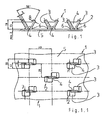
- FIG. 1 shows the plastic or knobbed plate 1 according to the invention with a base plate 5 the knobs or wing element pairs 2 are provided in one piece. Latter each consist of two expanding wing elements 3, which over one Support web 4 are interconnected. Wing elements 3, webs 4 and Base plate 5 are thus in one piece. As mentioned, they get in the way extrusion calendering.
- dimensions are in mm as well as degrees. They give preferred values of the knob plate 1 according to the invention again.
- the supporting webs 4 that they are at least 70%, preferably 80% and more of the amount of Have wing elements 3.
- the radius of the Bow 6 is preferably about 50% of the thickness of a wing element in the 1.
- the wing elements 3 close an expansion angle one that is usually 50 to 60 degrees; preferably it is 56 degrees.
- the wing elements 3 or knobs of the wing element pairs 2 according to FIG. 1 and FIG. 1.1 are essentially offset against one another over their width 7, as is the case results from Fig. 1.1. There you can also see that they are on their two edge regions adjacent to one another are connected to one another via the webs 4 are.
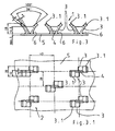
- Fig. 2 shows a modified embodiment of the object of Fig. 1.
- Die Wing elements 3 are wider than those shown in FIG. 2.1 Wing elements of Fig. 1 executed. They are the same in terms of their thickness 8 sized. In addition, in contrast to FIG. 1, they are only minor offset against each other. The webs are arranged approximately in the center of the width 7.
- the embodiment of the knobbed plate 1 according to FIGS. 3 and 3.1 differs from that according to FIGS. 1 and 2 essentially in that that the wing elements 3 in their upper area 3.1, the foot area with the arches 6 is opposite, are bent outwards and thus the upper areas 3.1 include a larger spread angle than the actual ones Wing elements 3. This results from Fig. 3.
- the spread angle of Wing elements 3 there again are 56 degrees in the foot area; that of the top Area 3.1 of the wing elements 3> 90 degrees.
- the increased spreading angle in the upper region 3.1 of the wing elements causes an improved adhesion of the wing element pairs 2 overall in the Concrete substructure.
- FIG. 4 shows a similar embodiment of the knobbed plate according to the invention with Fig. 4.1.
- the wing elements 3 of the individual wing element pairs 2 are again spread outward in their upper regions 3.1 than in that Area that extends to the upper end of the support web 4.
- the wing elements 3 are comparatively wide; see. Reference number 7. They are in alignment with each other provided, so not offset from each other.
- the support webs 4 are each in the middle provided with respect to the width 7 of the wing elements.
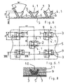
- FIG. 8 This condition is shown in more detail in FIG. 8.
- An arrow 10 represents the itself building up groundwater pressure within the wells 9.
- pent-up water In the Wells 9 is shown pent-up water.
- the invention Concrete surrounding the knob plate is designated by 11.
- Plastic plate 1 shown. These are wing element pairs 2 with uniform spread angle.
- the wing elements 3 have different Spread out.
- Two support elements connect the wing elements 3 to one another.
- the Outer edges of the element 3 of small thickness are with the opposite wider wing element 3 connected so that the recess 9 across the width of the wing element 3 extends smaller width.
- the wing element 3 larger Width protrudes beyond this recess 9, as shown in Fig. 6.6 in plan view shows.
- 7 with FIG. 7.1 show further possible exemplary embodiments of the Invention, regardless of whether the wing elements 3 in their upper region 3.1 are spread further or not with diagonally arranged support webs 4 between wing elements 3; see 7.1.
- There are four knob shapes 3.2 to 3.6 are shown.
- the support webs 4 take in about the width 7 of the support webs in the connection area between the support web 4 and Wing element 3 a.
- the support webs can be between the two wing elements 4, however, taper or become narrower in thickness, as is shown in FIG. 7.1 is shown graphically.
- thermoplastic material for the plastic sheet 1 according to the invention especially PVC, PE, PP, PVDF and ECTFE.
- PVC, PE, PP, PVDF and ECTFE can be made the plastic plate 1 according to the invention in particular by the method, such as it is described in EP 0 436 058 B1.
Abstract
Description
Die Erfindung bezieht sich auf eine Kunststoffplatte, insbesondere zum Auskleiden von Betonbauteilen, vorzugsweise aus thermoplastischem Kunststoff, mit auf mindestens einer Seite einstückig mit ihr ausgebildeten sich verspreizenden Flügelelementen, die in ihrem Fußbereich über Stützstege miteinander verbunden sind.The invention relates to a plastic plate, in particular for Lining concrete components, preferably made of thermoplastic, with integrally formed with it on at least one side expansive wing elements, in their foot area via support webs are interconnected.
Noppenplatten aus Kunststoff finden insbesondere Anwendung im Betonbehälterbau, wenn es gilt, flüssigkeits- und auch gasdichte, chemikalienresistente Behälter zu erstellen. Die Kunststoffplatten bilden die Auskleidung solcher Behälter. Sie erbringen die Beständigkeit gegen die Chemikalien und Flüssigkeiten. Die mechanische Festigkeit der Gesamtkonstruktion wird im wesentlichen von der Betonkonstruktion erbracht. Schwierigkeiten bereitet in aller Regel die Verbindung der Kunststoffplatten mit der Betonkonstruktion, da die glatte Kunststoffplatte keine feste mechanische Verbindung mit dem Beton eingeht. Die Zuhilfenahme von Klebern führt zu keinen langfristig zufriedenstellenden Ergebnissen.Knob plates made of plastic are used in particular Concrete container construction, if necessary, liquid and gas tight, to create chemical resistant containers. The plastic plates form the Lining such containers. They provide resistance to the Chemicals and liquids. The mechanical strength of the Overall construction is essentially provided by the concrete construction. The connection of the plastic plates usually presents difficulties the concrete structure, since the smooth plastic plate is not a solid mechanical one Connects with the concrete. The use of glue leads to no long-term satisfactory results.
Aus diesem Grunde sind verschiedene Verankerungselemente mit Hinterschneidungen vorgeschlagen worden, die auf einer Seite der Kunststoffplatte angebracht und die bei der Herstellung des Behälters einbetoniert werden. Auf diese Weise wird die erwünschte feste Verbindung zwischen Kunststoffplatte und Betonunterkonstruktion zwar erreicht, die Anbringung der bekannten Verankerungselemente an den Kunststoffplatten ist jedoch vergleichsweise aufwendig, da sie nachträglich erfolgt und mehrere Arbeitsschritte benötigt.For this reason, various anchoring elements are included Undercuts have been proposed on one side of the Plastic plate attached and concreted in the manufacture of the container become. In this way, the desired firm connection between Plastic plate and concrete substructure achieved, the attachment of the known anchoring elements on the plastic plates, however comparatively complex, since it is done retrospectively and several Work steps required.
Aus der EP 0 436 058 B1 ist eine Noppenplatte der infrage stehenden Art sowie ein Verfahren zu ihrer Herstellung bekannt, mit dessen Hilfe es möglich ist, Kunststoffplatten zum Auskleiden von Betonbauwerken mit einstückig an ihr vorgesehenen Noppen herzustellen. Die Noppen sind sich verspreizende Flügelelemente, die beim Auskleiden von Betonbauteilen oder Betonbauwerken mit der Kunststoffplatte einbetoniert werden. Diese Noppenplatten sind aufgrund der kontinuierlichen Herstellung mittels des in der genannten Patentschrift beschriebenen Verfahrens kontinuierlich und somit vergleichsweise preiswert herzustellen. Auch ist durch die gespreizt angeordneten Flügelelemente und der damit praktisch gegebenen Hinterschneidung eine sehr dauerhafte Befestigung der Kunststoffplattenauskleidung am Betonbauwerk gegeben.EP 0 436 058 B1 describes a knobbed plate of the type in question as well a process for their preparation is known, by means of which it is possible Plastic panels for lining concrete structures with one piece on it to produce the provided knobs. The knobs are spreading Wing elements used when lining concrete components or concrete structures can be concreted in with the plastic plate. These dimpled sheets are due the continuous production by means of the in said patent described method continuously and therefore comparatively inexpensive manufacture. Also is by the spread wing elements and the thus practically given undercut a very permanent attachment of the Plastic panel lining given on the concrete structure.
Es hat sich indessen gezeigt, daß ein Bedarf an derartigen Noppenplatten besteht, die im Falle der Erdverlegung besondere Grundwasser-Druckfestigkeit aufweisen.However, it has been shown that there is a need for such knobbed panels, which have special groundwater pressure resistance in the case of underground laying.
Die Aufgabe der Erfindung besteht somit darin, eine Kunststoffplatte der eingangs genannten Art, insbesondere zum Auskleiden von Betonbauteilen, zu schaffen, die Grundwasserdrücken im Bereich von ≥ 1,5 bar auch im Langzeitverhalten standhält. Diese Noppenplatte soll darüber hinaus weiterhin im Wege des preisgünstigen Kalandrierens herstellbar sein.The object of the invention is therefore a plastic plate of the beginning mentioned type, in particular for lining concrete components, to create the Groundwater pressures in the range of ≥ 1.5 bar also in long-term behavior withstand. This knobbed plate should also continue in the way of inexpensive calendering can be produced.
Diese Aufgabe der Erfindung ist dadurch gelöst, daß die Höhe der Stützstege mindestens 70%, vorzugsweise mindestens 80 % der Höhe der Flügelelemente beträgt, die in ihrem Fußbereich bogenförmige Übergänge zur Kunststoffplatte aufweisen.This object of the invention is achieved in that the height of the support webs at least 70%, preferably at least 80% of the height of the wing elements is, the arcuate transitions to the plastic plate in their foot area exhibit.
Die erfindungsgemäße Ausbildung der Flügelelemente durch die besondere Gestaltung der Stützstege sowie der Fußbereiche eines jeden Flügelelementpaares wird die angestrebte erhöhte Langzeitfestigkeit der so gebildeten Noppen und ihrer Verankerung an der eigentlichen Kunststoffplatte erzielt. Langzeituntersuchungen haben gezeigt, daß die Dauer-Grundwasserdruckfestigkeit bei Auskleidung von Betonbauteilen oder Betonbauwerken bei 1,5 bis 6,0 bar liegt. Mit diesen herausragenden Werten ist die erfindungsgemäße Kunststoffplatte vor allem zum Auskleiden von erdverlegten Kanalrohrsystemen geeignet. The inventive design of the wing elements through the special Design of the support bars and the foot areas of each pair of wing elements the desired increased long-term strength of the studs and thus formed achieved their anchoring on the actual plastic plate. Long-term studies have shown that the permanent groundwater pressure resistance when lining concrete components or Concrete structures is 1.5 to 6.0 bar. With these outstanding values the plastic plate according to the invention especially for lining buried sewer pipe systems suitable.
Weitere Einzelheiten, Merkmale und Vorteile der Erfindung ergeben sich aus der folgenden Beschreibung mehrerer bevorzugter Ausfiihmngsbeispiele sowie anhand der schematischen Zeichnung und der Patentansprüche. Es zeigen - jeweils in Teilansicht -
- Fig. 1
- eine Seitenansicht einer ersten Ausführungsform der Erfindung;
- Fig. 1.1
- eine Draufsicht des Gegenstandes der Fig. 1;
- Fig. 2 bis Fig. 7
- gleichermaßen Seiten- und Draufsichten auf weitere Ausfühmngsbeispiele der erfindungsgemäßen Kunststoffplatte und
- Fig. 8
- einen Schnitt nach Linie VIII-VIII der Fig. 6.
- Fig. 1
- a side view of a first embodiment of the invention;
- Fig. 1.1
- a plan view of the object of Fig. 1;
- 2 to 7
- equally side and top views of further exemplary embodiments of the plastic plate according to the invention and
- Fig. 8
- a section along line VIII-VIII of Fig. 6th
In der nachfolgenden Beschreibung sind gleiche Basisteile der erfindungsgemäßen
Kunststoff- oder Noppenplatte 1 mit gleichen bzw. gleichartigen Bezugsziffern
versehen sind, so daß nicht sämtliche Fig. im Detail beschrieben werden. Dies
vorausgeschickt sei somit zunächst auf die Fig. 1 eingegangen. Sie zeigt die
erfindungsgemäße Kunststoff- oder Noppenplatte 1 mit einer Basisplatte 5, auf
der einstückig Noppen oder Flügelelementpaare 2 vorgesehen sind. Letztere
bestehen aus jeweils zwei sich verspreizenden Flügelelementen 3, die über einen
Stützsteg 4 miteinander verbunden sind. Flügelelemente 3, Stege 4 und
Grundplatte 5 sind somit insgesamt einstückig. Wie erwähnt, werden sie im Wege
des Extrusionskalandrierens hergestellt.In the following description, the same basic parts of the invention
Plastic or
In der vorliegenden Zeichnung und ebenso in der Fig. 1 sind Maßangaben in mm
sowie Gradangaben enthalten. Sie geben bevorzugte Werte der
erfindungsgemäßen Noppenplatte 1 wieder. Zu den Stützstegen 4 ist auszuführen,
daß sie mindestens 70%, vorzugsweise 80% und mehr der Höhe der
Flügelelemente 3 aufweisen. Wie sich aus den Fig. gleichermaßen ergibt, gehen
die Flügelelemente an ihrem Fuße in Form eines Bogens 6 in die Grundplatte 5
über. Dieser Übergang erfolgt vorzugsweise stetig. Hierdurch ergibt sich eine
vergleichsweise breite Verbindungsfläche der Noppen 2 mit eben dieser
Grundplatte 5 mit einer entsprechend verringerten Belastung der
Zugbeanspruchung pro Flächeneinheit im Fußbereich der Noppen. Der Radius des
Bogens 6 beträgt vorzugsweise etwa 50% der Dicke eines Flügelelementes in der
Ansicht nach Fig. 1.In the present drawing and also in FIG. 1, dimensions are in mm
as well as degrees. They give preferred values of the
Wie die Zeichnungen zeigen, schließen die Flügelemente 3 einen Spreizwinkel
ein, der im Regelfall 50 bis 60 Grad beträgt; vorzugsweise beträgt er 56 Grad.As the drawings show, the
Die Flügelemente 3 oder Noppen der Flügelelementpaare 2 gemäß Fig. 1 und Fig.
1.1 sind im wesentlichen über ihre Breite 7 gegeneinander versetzt, wie sich dies
aus Fig. 1.1 ergibt. Dort ist ebenfalls ersichtlich, daß sie an ihren beiden
zueinander angrenzenden Randbereichen über die Stege 4 miteinander verbunden
sind.The
Fig. 2 zeigt eine abgeänderte Ausführungsform des Gegenstands der Fig. 1. Die
Flügelelemente 3 sind hier, wie Fig. 2.1 zeigt, breiter gegenüber den
Flügelelementen der Fig. 1 ausgeführt. Hinsichtlich ihrer Dicke 8 sind sie gleich
bemessen. Darüber hinaus sind sie im Gegensatz zur Fig. 1 nur geringfügig
gegeneinander versetzt. Die Stege sind in etwa mittig zur Breite 7 angeordnet.Fig. 2 shows a modified embodiment of the object of Fig. 1. Die
Die Ausführungsform der erfindungsgemäßen Noppenplatte 1 gemäß Fig. 3 und
3.1 unterscheidet sich von der gemäß den Fig. 1 und 2 im wesentlichen dadurch,
daß die Flügelelemente 3 in ihrem oberen Bereich 3.1, der dem Fußbereich mit
den Bögen 6 gegenüberliegt, nach außen abgeknickt sind und daß somit die
oberen Bereiche 3.1 einen größeren Spreizwinkel einschließen als die eigentlichen
Flügelelemente 3. Dies ergibt sich aus Fig. 3. Der Spreizwinkel der
Flügelelemente 3 beträgt dort im Fußbereich wiederum 56 Grad; der des oberen
Bereiches 3.1 der Flügelelemente 3 > 90 Grad.The embodiment of the
Der vergrößerte Spreizwinkel im oberen Bereich 3.1 der Flügelelemente bewirkt eine verbesserte Haftung der Flügelelementpaare 2 insgesamt in der Betonunterkonstruktion. The increased spreading angle in the upper region 3.1 of the wing elements causes an improved adhesion of the wing element pairs 2 overall in the Concrete substructure.
Ansonsten sind die Flügelelemente 3 eines jeden Flügelelementpaares 2 in
gleicher Weise angeordnet wie beim Ausführungsbeispiel gemäß Fig. 1, wie dies
ein Vergleich der Fig. 3.1 und 1.1 zeigt.Otherwise, the
Eine ähnliche Ausführungsform der erfindungsgemäßen Noppenplatte zeigt Fig. 4
mit Fig. 4.1. Die Flügelelemente 3 der einzelnen Flügelelementpaare 2 sind
wiederum in ihren oberen Bereichen 3.1 nach außen weiter gespreizt als in dem
Bereich, der bis zum oberen Ende des Stützsteges 4 reicht. Die Flügelelemente 3
sind vergleichsweise breit; vgl. Bezugsziffer 7. Sie sind fluchtend zueinander
vorgesehen, also nicht zueinander versetzt. Die Stützstege 4 sind jeweils mittig
bezüglich der Breite 7 der Flügelelemente vorgesehen.4 shows a similar embodiment of the knobbed plate according to the invention
with Fig. 4.1. The
Fig. 5 und 5.1 zeigen Flügelelementpaare mit mehreren Stützstegen 4 pro
Flügelelementpaar 2. Im vorliegenden Fall handelt es sich um vier Stützstege 4,
wobei die beiden äußeren Stützstege als Endstützstege 4.1 bezeichnet sind. Die
Flügelelemente 3 sind wiederum fluchtend zueinander vorgesehen. Auf diese
Weise stellen sich drei Vertiefungen 9 ein, die sich insofern vorteilhaft auswirken,
als sich im Falle von Grundwasserdruck aus dem Betonbauwerk auf die
Noppenplatte 1 ein gewisser zusätzlicher Grundwasserdruck dort aufbauen kann
und somit zur Entlastung der Beanspruchung des Fußbereiches der
Flügelelementpaare im Bereich der Bogen 6 beiträgt.5 and 5.1 show pairs of wing elements with several supporting
Diese Bedingung ist in Fig. 8 näher dargestellt. Ein Pfeil 10 repräsentiert den sich
aufbauenden Grundwasserdruck innerhalb der Vertiefungen 9. In den
Vertiefungen 9 ist aufgestautes Wasser gezeigt. Der die erfindungsgemäße
Noppenplatte umgebende Beton ist mit 11 bezeichnet.This condition is shown in more detail in FIG. 8. An
In Fig. 6 schließlich ist eine weitere Variante der erfindungsgemäßen
Kunststoffplatte 1 dargestellt. Es handelt sich hierbei um Flügelelementpaare 2
mit einheitlichen Spreizwinkel. Die Flügelelemente 3 weisen unterschiedliche
Breite auf. Zwei Stützelemente verbinden die Flügelelemente 3 miteinander. Die
Außenkanten des Elementes 3 geringer Dicke sind mit dem gegenüberliegenden
breiteren Flügelelement 3 verbunden, so daß sich die Vertiefung 9 über die Breite
des Flügelelementes 3 geringerer Breite erstreckt. Das Flügelelement 3 größerer
Breite ragt über diese Vertiefung 9 hinaus, wie dies Fig. 6.6 in der Draufsicht
zeigt. Fig. 7 mit der Fig. 7.1 zeigen weitere mögliche Ausfiihrungsbeispiele der
Erfindung, unabhängig davon, ob die Flügelelemente 3 in ihrem oberen Bereich
3.1 weiter gespreizt sind oder nicht mit diagonal angeordneten Stützstegen 4
zwischen versetzt zueinander angeordneten Flügelelementen 3; siehe 7.1. Es sind
hierzu vier Noppenformen 3.2 bis 3.6 gezeigt. Die Stützstege 4 nehmen dabei in
etwa die Breite 7 der Stützstege im Verbindungsbereich zwischen Stützsteg 4 und
Flügelelement 3 ein. Zwischen den beiden Flügelelementen können die Stützstege
4 sich jedoch verjüngen bzw. in ihrer Dicke enger werden, wie dies in der Fig. 7.1
zeichnerisch dargestellt ist.6 is a further variant of the
Als thermoplastischer Werkstoff für die erfindungsgemäße Kunststoffplatte 1,
insbesondere PVC, PE, PP, PVDF und ECTFE infrage. Hergestellt werden kann
die erfindungsgemäße Kunststoffplatte 1 insbesondere nach dem Verfahren, wie
es in der EP 0 436 058 B1 beschrieben ist.As a thermoplastic material for the
Claims (15)
- A synthetic panel (1), in particular for lining concrete building components, preferably made from thermoplastic synthetic material, having on at least one side and constructed in one piece therewith spreading wing elements (3) which are connected to one another in their base region by way of supporting webs (4), characterised in that the height of the supporting webs (4) is at least 70%, preferably at least 80%, of the height of the wing elements (3), which have in their base region arcuate transitions (6) to the synthetic panel (1).
- A synthetic panel according to Claim 1, characterised in that the radius of the transition is approximately 50% as large as the thickness of a wing element.
- A synthetic panel according to Claim 1 or 2, characterised in that the wing elements (3) form a larger spreading angle at their free ends, beginning from the end of the supporting webs (4) remote from the synthetic panel, than in the region of the supporting webs (4).
- A synthetic panel according to at least one of the preceding claims, characterised in that in each case two wing elements (3) are arranged offset from one another and are connected to one another by way of at least one supporting web (4).
- A synthetic panel according to Claim 4, characterised in that the wing elements (3) of a pair (2) of wing elements are offset from one another over virtually their entire width and are connected to one another in their mutually adjoining regions by way of a supporting web (3).
- A synthetic panel according to at least one of Claims 1 to 3, characterised in that the wing elements (3) of a pair (2) of wing elements are arranged to be flush with one another and the respective supporting web (4) is provided between the wing elements in a symmetrical arrangement.
- A synthetic panel according to at least one of the preceding claims, characterised in that the pairs (2) of wing elements each have two end supporting webs (4.1).
- A synthetic panel according to at least one of the preceding claims, characterised in that a respective end supporting web (4.1) is provided on either side of the pairs (2) of wing elements having wing elements (3) of the same width.
- A synthetic panel according to Claim 8, characterised in that between the end supporting webs (4, 1) there are provided further supporting webs (4).
- A synthetic panel according to at least one of the preceding claims, characterised in that the wing elements (3) have different widths (7) and the supporting webs (4) extend from the longitudinal sides of the wing element (3) of smaller width perpendicular to the wing element (3) of greater width.
- A synthetic panel according to at least one of the preceding claims, characterised in that the wing elements (3), arranged offset from one another, of a pair (2) of wing elements are connected to one another by way of a respective supporting web (4) which has substantially the same width as the wing elements (3).
- A synthetic panel according to at least one of the preceding claims, characterised in that the width (7) of the supporting web (4) is smaller between two wing elements (3) than in the region of connection to the wing elements (3) (Fig. 7.1).
- A synthetic panel according to at least one of the preceding claims, characterised in that the wing elements have a rectangular, square or polygonal cross-section.
- A synthetic panel according to Claim 13, characterised in that the wing elements have discontinuous or rounded edges.
- A synthetic panel according to at least one of Claims 1 to 12, characterised in that the wing elements have a round, oval or elliptical cross-section.
Priority Applications (2)
| Application Number | Priority Date | Filing Date | Title |
|---|---|---|---|
| DK00909121T DK1165905T3 (en) | 2000-01-31 | 2000-01-31 | Plastic sheet, especially for cladding of concrete building parts |
| PT00909121T PT1165905E (en) | 2000-01-31 | 2000-01-31 | SITE PLATE, ESPECIALLY FOR COMPONENT COATING IN BETA |
Applications Claiming Priority (1)
| Application Number | Priority Date | Filing Date | Title |
|---|---|---|---|
| PCT/EP2000/000729 WO2001057340A1 (en) | 2000-01-31 | 2000-01-31 | Synthetic panel, especially for lining concrete building components |
Publications (2)
| Publication Number | Publication Date |
|---|---|
| EP1165905A1 EP1165905A1 (en) | 2002-01-02 |
| EP1165905B1 true EP1165905B1 (en) | 2004-10-27 |
Family
ID=8163815
Family Applications (1)
| Application Number | Title | Priority Date | Filing Date |
|---|---|---|---|
| EP00909121A Expired - Lifetime EP1165905B1 (en) | 2000-01-31 | 2000-01-31 | Synthetic panel, especially for lining concrete building components |
Country Status (14)
| Country | Link |
|---|---|
| US (1) | US6655103B1 (en) |
| EP (1) | EP1165905B1 (en) |
| JP (1) | JP4339545B2 (en) |
| KR (1) | KR100701972B1 (en) |
| AT (1) | ATE280872T1 (en) |
| AU (1) | AU770050B2 (en) |
| CA (1) | CA2338655C (en) |
| DE (1) | DE50008423D1 (en) |
| DK (1) | DK1165905T3 (en) |
| ES (1) | ES2234570T3 (en) |
| IL (1) | IL140991A0 (en) |
| PT (1) | PT1165905E (en) |
| TW (1) | TW509744B (en) |
| WO (1) | WO2001057340A1 (en) |
Cited By (1)
| Publication number | Priority date | Publication date | Assignee | Title |
|---|---|---|---|---|
| EP2806083A1 (en) | 2013-05-24 | 2014-11-26 | Agru Kunststofftechnik Gmbh | Device for fixing plastic boards to structures or components and method for lining components or structures with plastic boards |
Families Citing this family (14)
| Publication number | Priority date | Publication date | Assignee | Title |
|---|---|---|---|---|
| JP4339545B2 (en) * | 2000-01-31 | 2009-10-07 | アロイス・グルーバー・ゲーエムベーハー | Synthetic resin boards, especially lining materials |
| JP4361049B2 (en) * | 2004-12-06 | 2009-11-11 | コリア ナショナル ハウジング コーポレーション | Assembled box-type steel pipe column for filling concrete and method for producing the same |
| PT1715196E (en) * | 2005-04-22 | 2012-01-17 | Agru Kunststofftechnik Gmbh | Synthetic panels to cover concrete constructions parts |
| KR200446289Y1 (en) * | 2007-10-16 | 2009-10-14 | 박건창 | Concrete laying type plastic panel |
| US7788865B2 (en) * | 2008-02-18 | 2010-09-07 | Trim-Tex, Inc. | Drywall trimming element with compound locking feature |
| US20120023845A1 (en) * | 2008-12-23 | 2012-02-02 | Chevron U.S.A. Inc. | Base Mat Assembly And Method For Constructing The Same |
| TWM365962U (en) * | 2009-03-03 | 2009-10-01 | Yao-Zong Chen | Raised floor unit |
| US8075221B2 (en) * | 2009-11-12 | 2011-12-13 | Hortech, Inc. | Paver assembly |
| JP5903772B2 (en) | 2011-04-11 | 2016-04-13 | ソニー株式会社 | Solid-state imaging device and camera system |
| JP2016037749A (en) * | 2014-08-07 | 2016-03-22 | 株式会社栗本鐵工所 | Repair structure for inner surface of water channel and water channel repair plate |
| CN104370010B (en) * | 2014-09-11 | 2017-01-18 | 韦琪琪 | Container of plastic and concrete structure |
| CN105951970A (en) * | 2016-04-28 | 2016-09-21 | 成都津泽环保工程有限责任公司 | Liner structure for concrete pipeline and concrete pipeline |
| CN106003698A (en) * | 2016-05-28 | 2016-10-12 | 浙江双林机电科技有限公司 | Production method for concrete protection lining |
| BE1026591B1 (en) * | 2018-09-06 | 2020-04-06 | M H C Nv | Concrete building element |
Family Cites Families (6)
| Publication number | Priority date | Publication date | Assignee | Title |
|---|---|---|---|---|
| EP0436058B1 (en) | 1990-01-05 | 1993-10-20 | agru Alois Gruber G.m.b.H. | Process for producing plastic sheets with protuberances and plastic sheet with protuberances |
| US5168682A (en) * | 1990-10-05 | 1992-12-08 | Palle Rye | Plastic liners for concrete structural elements and the elements and structures produced thereby |
| US5351720A (en) * | 1992-03-10 | 1994-10-04 | Link-Pipe, Inc. | Apparatus for repairing conduits |
| DE9300859U1 (en) * | 1993-01-22 | 1993-05-27 | Agru Alois Gruber Ges.M.B.H., Bad Hall, At | |
| WO1996016790A1 (en) * | 1994-12-02 | 1996-06-06 | Sure Grip North America, L.L.C. | A lining system and method for installing a plastic liner |
| JP4339545B2 (en) * | 2000-01-31 | 2009-10-07 | アロイス・グルーバー・ゲーエムベーハー | Synthetic resin boards, especially lining materials |
-
2000
- 2000-01-31 JP JP2001555961A patent/JP4339545B2/en not_active Expired - Lifetime
- 2000-01-31 AU AU31512/00A patent/AU770050B2/en not_active Expired
- 2000-01-31 AT AT00909121T patent/ATE280872T1/en active
- 2000-01-31 ES ES00909121T patent/ES2234570T3/en not_active Expired - Lifetime
- 2000-01-31 CA CA002338655A patent/CA2338655C/en not_active Expired - Lifetime
- 2000-01-31 WO PCT/EP2000/000729 patent/WO2001057340A1/en active IP Right Grant
- 2000-01-31 EP EP00909121A patent/EP1165905B1/en not_active Expired - Lifetime
- 2000-01-31 US US09/744,971 patent/US6655103B1/en not_active Expired - Lifetime
- 2000-01-31 KR KR1020017002029A patent/KR100701972B1/en active IP Right Grant
- 2000-01-31 DK DK00909121T patent/DK1165905T3/en active
- 2000-01-31 PT PT00909121T patent/PT1165905E/en unknown
- 2000-01-31 DE DE50008423T patent/DE50008423D1/en not_active Expired - Lifetime
- 2000-01-31 IL IL14099100A patent/IL140991A0/en not_active IP Right Cessation
-
2001
- 2001-02-13 TW TW090103129A patent/TW509744B/en not_active IP Right Cessation
Cited By (1)
| Publication number | Priority date | Publication date | Assignee | Title |
|---|---|---|---|---|
| EP2806083A1 (en) | 2013-05-24 | 2014-11-26 | Agru Kunststofftechnik Gmbh | Device for fixing plastic boards to structures or components and method for lining components or structures with plastic boards |
Also Published As
| Publication number | Publication date |
|---|---|
| DK1165905T3 (en) | 2004-12-06 |
| TW509744B (en) | 2002-11-11 |
| CA2338655C (en) | 2008-09-16 |
| WO2001057340A1 (en) | 2001-08-09 |
| DE50008423D1 (en) | 2004-12-02 |
| KR20010110289A (en) | 2001-12-12 |
| ES2234570T3 (en) | 2005-07-01 |
| PT1165905E (en) | 2005-01-31 |
| US6655103B1 (en) | 2003-12-02 |
| AU3151200A (en) | 2001-08-14 |
| ATE280872T1 (en) | 2004-11-15 |
| CA2338655A1 (en) | 2001-07-31 |
| IL140991A0 (en) | 2002-02-10 |
| JP2003521608A (en) | 2003-07-15 |
| EP1165905A1 (en) | 2002-01-02 |
| JP4339545B2 (en) | 2009-10-07 |
| KR100701972B1 (en) | 2007-04-02 |
| AU770050B2 (en) | 2004-02-12 |
Similar Documents
| Publication | Publication Date | Title |
|---|---|---|
| EP1165905B1 (en) | Synthetic panel, especially for lining concrete building components | |
| DE1684357B2 (en) | FORMWORK FOR THE PRODUCTION OF CONCRETE WALLS OR THE LIKE | |
| DE1634382C3 (en) | Formwork shell for the production of concrete slabs in the foundation | |
| CH667684A5 (en) | FORMSTEIN. | |
| DE60031763T2 (en) | Reinforcement reinforcement for prefabricated concrete slabs | |
| DE7631886U1 (en) | COMPONENT KIT FOR THE PRODUCTION OF BOX WALLS | |
| EP2625346A2 (en) | Metal ceiling substructure | |
| CH681031A5 (en) | ||
| DE3326109C2 (en) | Cobblestone | |
| WO2012126025A1 (en) | Device for spanning an expansion joint | |
| WO2000028157A1 (en) | Connecting element for pile-planks | |
| EP0075551B1 (en) | Noise barrier | |
| DE10160441B4 (en) | Window planking | |
| DE2454095A1 (en) | CANTILEVER ASBESTOS CEMENT PANELS, IN PARTICULAR AS ROOF TILES, AS WELL AS MANUFACTURING PROCESS | |
| DE2343866B2 (en) | Drainage plate made of plastic | |
| DE2355880A1 (en) | Sheet metal profile reinforced concrete slab - has embedded omega profiles with perforated web and tension flange | |
| DE102019102697A1 (en) | Alignable formwork element | |
| DE202019106248U1 (en) | Formwork element for creating a toothed construction joint in a concrete part | |
| CH670128A5 (en) | ||
| DE202023002316U1 (en) | Concrete paving stone | |
| DE1609034C (en) | Filter pipe for wells | |
| AT374875B (en) | COUPLING, IN PARTICULAR FOR SHUTTERING | |
| DE102018129293A1 (en) | Expansion strip | |
| AT403183B (en) | Casing plate for erecting cast concrete walls - has casing skin, on rear side of which are arranged reinforcement components with rails provided at least on two opposite edges | |
| DE7408186U (en) | UNDERFLOOR LIGHT SHELL |
Legal Events
| Date | Code | Title | Description |
|---|---|---|---|
| PUAI | Public reference made under article 153(3) epc to a published international application that has entered the european phase |
Free format text: ORIGINAL CODE: 0009012 |
|
| 17P | Request for examination filed |
Effective date: 20010125 |
|
| AK | Designated contracting states |
Kind code of ref document: A1 Designated state(s): AT BE CH CY DE DK ES FI FR GB GR IE IT LI LU MC NL PT SE |
|
| GRAP | Despatch of communication of intention to grant a patent |
Free format text: ORIGINAL CODE: EPIDOSNIGR1 |
|
| GRAS | Grant fee paid |
Free format text: ORIGINAL CODE: EPIDOSNIGR3 |
|
| GRAA | (expected) grant |
Free format text: ORIGINAL CODE: 0009210 |
|
| AK | Designated contracting states |
Kind code of ref document: B1 Designated state(s): AT BE CH CY DE DK ES FI FR GB GR IE IT LI LU MC NL PT SE |
|
| REG | Reference to a national code |
Ref country code: GB Ref legal event code: FG4D Free format text: NOT ENGLISH |
|
| REG | Reference to a national code |
Ref country code: CH Ref legal event code: EP |
|
| REG | Reference to a national code |
Ref country code: SE Ref legal event code: TRGR |
|
| REG | Reference to a national code |
Ref country code: IE Ref legal event code: FG4D Free format text: GERMAN |
|
| REF | Corresponds to: |
Ref document number: 50008423 Country of ref document: DE Date of ref document: 20041202 Kind code of ref document: P |
|
| REG | Reference to a national code |
Ref country code: DK Ref legal event code: T3 |
|
| REG | Reference to a national code |
Ref country code: GR Ref legal event code: EP Ref document number: 20040404180 Country of ref document: GR |
|
| REG | Reference to a national code |
Ref country code: PT Ref legal event code: SC4A Effective date: 20041118 |
|
| REG | Reference to a national code |
Ref country code: ES Ref legal event code: FG2A Ref document number: 2234570 Country of ref document: ES Kind code of ref document: T3 |
|
| PLBE | No opposition filed within time limit |
Free format text: ORIGINAL CODE: 0009261 |
|
| STAA | Information on the status of an ep patent application or granted ep patent |
Free format text: STATUS: NO OPPOSITION FILED WITHIN TIME LIMIT |
|
| ET | Fr: translation filed | ||
| 26N | No opposition filed |
Effective date: 20050728 |
|
| PGFP | Annual fee paid to national office [announced via postgrant information from national office to epo] |
Ref country code: MC Payment date: 20100120 Year of fee payment: 11 |
|
| PGFP | Annual fee paid to national office [announced via postgrant information from national office to epo] |
Ref country code: CY Payment date: 20091222 Year of fee payment: 11 |
|
| PG25 | Lapsed in a contracting state [announced via postgrant information from national office to epo] |
Ref country code: MC Free format text: LAPSE BECAUSE OF NON-PAYMENT OF DUE FEES Effective date: 20110131 |
|
| PG25 | Lapsed in a contracting state [announced via postgrant information from national office to epo] |
Ref country code: CY Free format text: LAPSE BECAUSE OF NON-PAYMENT OF DUE FEES Effective date: 20110131 |
|
| REG | Reference to a national code |
Ref country code: DE Ref legal event code: R082 Ref document number: 50008423 Country of ref document: DE Representative=s name: ANWAELTE BURGER UND PARTNER RECHTSANWALTSKANZL, AT Ref country code: DE Ref legal event code: R082 Ref document number: 50008423 Country of ref document: DE Representative=s name: OPPERMANN, FRANK, DIPL.-ING., DE Ref country code: DE Ref legal event code: R082 Ref document number: 50008423 Country of ref document: DE Representative=s name: ANWAELTE BURGER UND PARTNER RECHTSANWALT GMBH, AT Ref country code: DE Ref legal event code: R082 Ref document number: 50008423 Country of ref document: DE Representative=s name: BURGER UND PARTNER RECHTSANWALT GMBH, AT Ref country code: DE Ref legal event code: R082 Ref document number: 50008423 Country of ref document: DE Representative=s name: ABP BURGER RECHTSANWALTSGESELLSCHAFT MBH, DE Ref country code: DE Ref legal event code: R082 Ref document number: 50008423 Country of ref document: DE Representative=s name: FRANK OPPERMANN, DE |
|
| REG | Reference to a national code |
Ref country code: DE Ref legal event code: R082 Ref document number: 50008423 Country of ref document: DE Representative=s name: ANWAELTE BURGER UND PARTNER RECHTSANWALTSKANZL, AT Ref country code: DE Ref legal event code: R082 Ref document number: 50008423 Country of ref document: DE Representative=s name: ANWAELTE BURGER UND PARTNER RECHTSANWALT GMBH, AT Ref country code: DE Ref legal event code: R082 Ref document number: 50008423 Country of ref document: DE Representative=s name: BURGER UND PARTNER RECHTSANWALT GMBH, AT Ref country code: DE Ref legal event code: R082 Ref document number: 50008423 Country of ref document: DE Representative=s name: ABP BURGER RECHTSANWALTSGESELLSCHAFT MBH, DE |
|
| REG | Reference to a national code |
Ref country code: CH Ref legal event code: NV Representative=s name: ABP PATENT NETWORK AG, CH |
|
| PG25 | Lapsed in a contracting state [announced via postgrant information from national office to epo] |
Ref country code: BE Free format text: LAPSE BECAUSE OF NON-PAYMENT OF DUE FEES Effective date: 20150131 |
|
| PGRI | Patent reinstated in contracting state [announced from national office to epo] |
Ref country code: BE Effective date: 20150507 |
|
| REG | Reference to a national code |
Ref country code: FR Ref legal event code: PLFP Year of fee payment: 17 |
|
| REG | Reference to a national code |
Ref country code: CH Ref legal event code: PCAR Free format text: NEW ADDRESS: OTHMARSTRASSE 8, 8008 ZUERICH (CH) |
|
| REG | Reference to a national code |
Ref country code: FR Ref legal event code: PLFP Year of fee payment: 18 |
|
| PGFP | Annual fee paid to national office [announced via postgrant information from national office to epo] |
Ref country code: FI Payment date: 20170130 Year of fee payment: 18 |
|
| REG | Reference to a national code |
Ref country code: FR Ref legal event code: PLFP Year of fee payment: 19 |
|
| REG | Reference to a national code |
Ref country code: DE Ref legal event code: R082 Ref document number: 50008423 Country of ref document: DE Representative=s name: ABP BURGER RECHTSANWALTSGESELLSCHAFT MBH, DE |
|
| PG25 | Lapsed in a contracting state [announced via postgrant information from national office to epo] |
Ref country code: FI Free format text: LAPSE BECAUSE OF NON-PAYMENT OF DUE FEES Effective date: 20180131 |
|
| PGFP | Annual fee paid to national office [announced via postgrant information from national office to epo] |
Ref country code: GR Payment date: 20181219 Year of fee payment: 20 |
|
| PGFP | Annual fee paid to national office [announced via postgrant information from national office to epo] |
Ref country code: FR Payment date: 20181219 Year of fee payment: 20 |
|
| PGFP | Annual fee paid to national office [announced via postgrant information from national office to epo] |
Ref country code: LU Payment date: 20190116 Year of fee payment: 20 |
|
| PGFP | Annual fee paid to national office [announced via postgrant information from national office to epo] |
Ref country code: DE Payment date: 20190103 Year of fee payment: 20 Ref country code: IE Payment date: 20190109 Year of fee payment: 20 Ref country code: NL Payment date: 20190110 Year of fee payment: 20 Ref country code: CH Payment date: 20190107 Year of fee payment: 20 Ref country code: GB Payment date: 20190110 Year of fee payment: 20 Ref country code: IT Payment date: 20190114 Year of fee payment: 20 Ref country code: ES Payment date: 20190205 Year of fee payment: 20 |
|
| PGFP | Annual fee paid to national office [announced via postgrant information from national office to epo] |
Ref country code: BE Payment date: 20190108 Year of fee payment: 20 Ref country code: AT Payment date: 20181221 Year of fee payment: 20 Ref country code: DK Payment date: 20190111 Year of fee payment: 20 Ref country code: SE Payment date: 20190107 Year of fee payment: 20 |
|
| PGFP | Annual fee paid to national office [announced via postgrant information from national office to epo] |
Ref country code: PT Payment date: 20190118 Year of fee payment: 20 |
|
| REG | Reference to a national code |
Ref country code: DE Ref legal event code: R071 Ref document number: 50008423 Country of ref document: DE |
|
| REG | Reference to a national code |
Ref country code: DK Ref legal event code: EUP Effective date: 20200131 |
|
| REG | Reference to a national code |
Ref country code: NL Ref legal event code: MK Effective date: 20200130 |
|
| REG | Reference to a national code |
Ref country code: GB Ref legal event code: PE20 Expiry date: 20200130 |
|
| REG | Reference to a national code |
Ref country code: IE Ref legal event code: MK9A |
|
| REG | Reference to a national code |
Ref country code: AT Ref legal event code: MK07 Ref document number: 280872 Country of ref document: AT Kind code of ref document: T Effective date: 20200131 |
|
| REG | Reference to a national code |
Ref country code: BE Ref legal event code: MK Effective date: 20200131 |
|
| REG | Reference to a national code |
Ref country code: CH Ref legal event code: PL |
|
| REG | Reference to a national code |
Ref country code: SE Ref legal event code: EUG |
|
| PG25 | Lapsed in a contracting state [announced via postgrant information from national office to epo] |
Ref country code: GB Free format text: LAPSE BECAUSE OF EXPIRATION OF PROTECTION Effective date: 20200130 Ref country code: IE Free format text: LAPSE BECAUSE OF EXPIRATION OF PROTECTION Effective date: 20200131 Ref country code: PT Free format text: LAPSE BECAUSE OF EXPIRATION OF PROTECTION Effective date: 20200212 |
|
| REG | Reference to a national code |
Ref country code: ES Ref legal event code: FD2A Effective date: 20200904 |
|
| PG25 | Lapsed in a contracting state [announced via postgrant information from national office to epo] |
Ref country code: ES Free format text: LAPSE BECAUSE OF EXPIRATION OF PROTECTION Effective date: 20200201 |