JP4339545B2 - Synthetic resin boards, especially lining materials - Google Patents
Synthetic resin boards, especially lining materials Download PDFInfo
- Publication number
- JP4339545B2 JP4339545B2 JP2001555961A JP2001555961A JP4339545B2 JP 4339545 B2 JP4339545 B2 JP 4339545B2 JP 2001555961 A JP2001555961 A JP 2001555961A JP 2001555961 A JP2001555961 A JP 2001555961A JP 4339545 B2 JP4339545 B2 JP 4339545B2
- Authority
- JP
- Japan
- Prior art keywords
- synthetic resin
- wing
- resin plate
- plate according
- members
- Prior art date
- Legal status (The legal status is an assumption and is not a legal conclusion. Google has not performed a legal analysis and makes no representation as to the accuracy of the status listed.)
- Expired - Lifetime
Links
Images


Classifications
-
- B—PERFORMING OPERATIONS; TRANSPORTING
- B65—CONVEYING; PACKING; STORING; HANDLING THIN OR FILAMENTARY MATERIAL
- B65D—CONTAINERS FOR STORAGE OR TRANSPORT OF ARTICLES OR MATERIALS, e.g. BAGS, BARRELS, BOTTLES, BOXES, CANS, CARTONS, CRATES, DRUMS, JARS, TANKS, HOPPERS, FORWARDING CONTAINERS; ACCESSORIES, CLOSURES, OR FITTINGS THEREFOR; PACKAGING ELEMENTS; PACKAGES
- B65D90/00—Component parts, details or accessories for large containers
- B65D90/02—Wall construction
- B65D90/04—Linings
- B65D90/041—Rigid liners fixed to the container
- B65D90/042—Rigid liners fixed to the container fixed pointwise or linewise
- B65D90/043—Rigid liners fixed to the container fixed pointwise or linewise the liners being in the form of tiles or panels
-
- Y—GENERAL TAGGING OF NEW TECHNOLOGICAL DEVELOPMENTS; GENERAL TAGGING OF CROSS-SECTIONAL TECHNOLOGIES SPANNING OVER SEVERAL SECTIONS OF THE IPC; TECHNICAL SUBJECTS COVERED BY FORMER USPC CROSS-REFERENCE ART COLLECTIONS [XRACs] AND DIGESTS
- Y10—TECHNICAL SUBJECTS COVERED BY FORMER USPC
- Y10T—TECHNICAL SUBJECTS COVERED BY FORMER US CLASSIFICATION
- Y10T428/00—Stock material or miscellaneous articles
- Y10T428/24—Structurally defined web or sheet [e.g., overall dimension, etc.]
- Y10T428/24802—Discontinuous or differential coating, impregnation or bond [e.g., artwork, printing, retouched photograph, etc.]
- Y10T428/24893—Discontinuous or differential coating, impregnation or bond [e.g., artwork, printing, retouched photograph, etc.] including particulate material
- Y10T428/24901—Discontinuous or differential coating, impregnation or bond [e.g., artwork, printing, retouched photograph, etc.] including particulate material including coloring matter
-
- Y—GENERAL TAGGING OF NEW TECHNOLOGICAL DEVELOPMENTS; GENERAL TAGGING OF CROSS-SECTIONAL TECHNOLOGIES SPANNING OVER SEVERAL SECTIONS OF THE IPC; TECHNICAL SUBJECTS COVERED BY FORMER USPC CROSS-REFERENCE ART COLLECTIONS [XRACs] AND DIGESTS
- Y10—TECHNICAL SUBJECTS COVERED BY FORMER USPC
- Y10T—TECHNICAL SUBJECTS COVERED BY FORMER US CLASSIFICATION
- Y10T428/00—Stock material or miscellaneous articles
- Y10T428/24—Structurally defined web or sheet [e.g., overall dimension, etc.]
- Y10T428/24942—Structurally defined web or sheet [e.g., overall dimension, etc.] including components having same physical characteristic in differing degree
-
- Y—GENERAL TAGGING OF NEW TECHNOLOGICAL DEVELOPMENTS; GENERAL TAGGING OF CROSS-SECTIONAL TECHNOLOGIES SPANNING OVER SEVERAL SECTIONS OF THE IPC; TECHNICAL SUBJECTS COVERED BY FORMER USPC CROSS-REFERENCE ART COLLECTIONS [XRACs] AND DIGESTS
- Y10—TECHNICAL SUBJECTS COVERED BY FORMER USPC
- Y10T—TECHNICAL SUBJECTS COVERED BY FORMER US CLASSIFICATION
- Y10T428/00—Stock material or miscellaneous articles
- Y10T428/29—Coated or structually defined flake, particle, cell, strand, strand portion, rod, filament, macroscopic fiber or mass thereof
- Y10T428/2982—Particulate matter [e.g., sphere, flake, etc.]
- Y10T428/2991—Coated
Abstract
Description
【0001】
本発明は合成樹脂板、特にライニングコンクリート材用の合成樹脂板に関し、好ましくは熱可塑性材料からなり、合成樹脂板の少なくとも一面に一体形成され、かつ支持部に支持用ウェブを有する展延翼状部材を備える。
【0002】
合成樹脂からなる突起物含有板は、特に、液漏れがなく、かつ気密性を有する耐薬品性コンクリート構造の製造を目的とする場合、コンクリート製タンク構造に使用される。合成樹脂板は、そのようなタンクのライニングを形成する。それによって薬品及び液体に対する耐性が与えられる。全体的な構造の機械的強度は、基本的にコンクリート構造によって与えられる。合成樹脂板をコンクリート構造に接続することは、該コンクリートに対して表面が平滑な合成樹脂板は固定された機械的接続をなさないことから問題がある。長期間にわたって満足のいく結果を得るには、接着剤は何ら助けにはならない。
【0003】
このため、アンダーカットを有するアンカー部材が提案されており、該部材はタンク製造の過程で合成樹脂板の一面に設けられ、かつコンクリートで固められる。このことは、実際に合成樹脂板とコンクリート基礎構造との間に所望の固定接合が達成されるが、合成樹脂板上に既知のアンカー部材を設ける操作は、引き続いて行われ、かついくつかの工程を必要とすることから比較的出費が嵩む。
【0004】
欧州特許第0 436 058 号 B1 は、問題となるタイプの突起物含有板及びその製造方法を開示しており、それによってコンクリート構造にライニングが施され、かつそれに一体的に形成された突起物を有する合板の製造が可能となる。突起物は、コンクリート成形品又はコンクリート構造が合成樹脂板によってライニングが施された場合にコンクリートで固められる展延翼状部材である。上記特許明細書に記載された方法を用いた連続生産のために、上記突起物含有板を連続することができるので比較的安価である。また、展延翼状部材及び実際に設けられるアンダーカットによってコンクリート構造上にライニングされた合成樹脂板の結合がたいへん耐久性のあるものとなる。
【0005】
しかし、地下に埋設する場合、地下水に対して特有の耐性を持つそのような突起物含有板が必要であることが知られている。
【0006】
したがって、本発明の目的は長期間たっても範囲が≧1.5バールの地下水圧に耐えうる序で述べたタイプの合成樹脂板、特にライニングコンクリート材用のものを提供することである。さらに、上記突起物含有板もまた経済的に圧延によって製造可能である。
【0007】
このような本発明の目的は、支持用ウェブの高さが翼状部材の高さの少なくとも70%、好ましくは少なくとも80%であり、後者はその支持部において合成樹脂板に対して弓状の渡り部を有するようにすることである。
【0008】
本発明にもとづく翼状部部材の設計によって、各翼状部材対の支持用ウェブ及び支持部の特定の構成によって、このように形成された突起部及びその実際の合成樹脂板上への固定に対して求められている長期にわたる強度を高めることが達成される。長期間にわたる研究によって、コンクリート成形品又はコンクリート構造に対してライニングが施された際の地下水に対する耐性が1.5から6.0バールであることが示された。そのような優れた値によって、本発明にもとづく合成樹脂板は、特に埋設された下水管系にライニングを施すことに適している。
【0009】
本発明のさらなる詳細、特徴及び利点は、以下のいくつかの好ましい実施形態例の記載と模式的図面の参照、さらに特許請求の範囲によって得ることができる。
【0010】
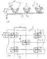
以下の説明では、本発明にもとづく合成樹脂板又は突起物含有板1は同一又は類似の名称が与えられており、そのため全ての図に対して詳細に説明する必要はない。このことを念頭に置いて、最初に図1のA、Bについて説明する。これらの図は、突起物4又は翼状部材対2が基板5上に一体成形された本発明にもとづく合成樹脂板又は突起物含有板1を示す。後者は各々2つの展延翼状部3を有するもので、該展延翼状部3は支持用ウェブ4を介して互いに接続している。したがって、翼状部材3、ウェブ4及び基板5はすべて互いに一体化している。既に述べたように、それらは押し出し圧延(EXTRUSION CALENDERING)によって製造される。
【0011】
本図面1のA、Bでは、MM及び度での測定が含まれる。それらは本発明にもとづく突起物含有板1の好ましい値を表す。支持用ウェブ4に関する限り、それらの高さは翼状部材3の高さの少なくとも70%、好ましくは80%以上であることを指摘しておくべきである。図から等しく推測できるように、翼状部材はその支持部分のところで円弧部6のかたちで基板5と一体化している。このような渡り部は、好ましくは連続している。このことによって、突起部とこのまさしく基板5との間に比較的広い接続面を与え、それに対応して突起部の支持部において単位表面積あたりの引張荷重が減少する。円弧部6の半径は、好ましくは図1のAにもとづく描写では翼状部材の厚さの約50%である。
【0012】
図1のAに示すように、翼状部材3は一般に50乃至60度、好ましくは56度である広がり角度を囲む。
【0013】
図1のA及び図1のBに基づく翼状部材対2の翼状部材3又は突起物は、図1のBから推測することができるように、基本的にそれらの幅7を越えて互いにオフセットしている。同様に、2つの相互に隣接した境界領域でウェブ4を介して違いに接続していることが上記の図から理解することができる。
【0014】
図2は、図1の主題の変形例を示す。この場合、図2のAに示すように、翼状部材3は図1のA、Bの翼状部材3よりも広くなるように設計されている。それらの厚さ8は等しい。さらに、図1のA、Bとは異なり、ほんのわずかに互いにオフセットしている。ウェブは幅7に関してほぼ中心に配置されている。
【0015】
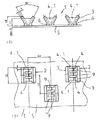
図3のA及び図3のBの本発明にもとづく突起物含有板1の実施形態例は、図1のA、B及び図2のA、Bのものと本質的に翼状部材3は円弧部6を有する支持部と反対側に位置したその上部3.1で外側方向に屈曲している点で、また上部3.1がそれによって実際の翼状部材3よりもより大きい広がり角度を囲む。このことは図3のAから推測される。翼状部材3の広がり角度は、支持部で56度であり、翼状部材3の上部3.1では、>90度である。
【0016】
翼状部材の上部3.1における広がり角度がより大きいことによってコンクリー基礎構造において全体的な翼状部材対2の粘着性が改善される。
【0017】
さもなければ、各翼状部材対2の翼状部材3は、図3のA及び1のAに示すものと比較して、図1のA、Bにもとづく模範的な実施形態と同様に配置される。
【0018】
図4のA及びBは本発明にもとづく突起物含有板と同様の実施形態例を示す。個々の翼状部材対の翼状部材3は、支持用ウェブ4の上端部まで延びる領域方向よりも再び上部3.1方向にさらに外側に広がる。翼状部材3は比較的に広い。すなわち符号7を見よ。それらは互いに一直線上にあり、すなわち互いにオフセットされていない。支持用ウェブ4は、翼状部材の幅7についてみると各々中心に設けられている。
【0019】
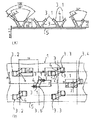
図5のA及びBは、翼状部材対2あたり複数の支持用ウェブ4を有する翼状部材を示している。本例では、4つの支持用ウェブ4と、端部支持用ウェブ4.1と呼ばれる2つの外側支持用ウェブがある。そして次に、翼状部材3は互いに一直線上に設けられている。このことによって、コンクリート構造上に地下水圧にさらされている突起物含有板1の場合、ある一定の地下水圧がさらに増大して円弧部6の領域で翼状部材対の支持部に対する荷重の軽減に貢献する限りにおいて有利な効果を有する凹部9が3つ形成される。
この状態は、図8によりいっそう明確に図示されている。矢印10は凹部9に増大された地下水圧を表す。溜まった水が凹部9に示される。本発明にもとづく突起物含有板を囲むコンクリートを11で示す。
【0020】
最後に、図6のA、Bは本発明にもとづく合成樹脂板1の別の変形例を示す。ここで翼状部材対2は均一な広がり角度を有する。翼状部材3は幅が異なる。2つの支持部材によって翼状部材3が互いに結合している。厚さが小さい部材3の外縁が反対側にあるより広い翼状部材3に結合し、それによって凹部9が幅の小さい翼状部材3の幅を超えて延びる。大きい幅の翼状部材3は、図6のAの平面図に示すように前記凹部9を越えて突出する。さらに、図7のA及びBは翼状部材3がその上部3.1においてよりいっそう広がるか、相互にオフセットする翼状部材3Aで対角線上に配置されたかどうかにかかわらず、本発明の実現可能な模範的実施形態を示す。すなわち、図7のAを見よ。この目的のために、4つの突起物形状3.2乃至3.6が示されている。この場合、支持用ウェブ4は、ほぼ該支持用ウェブ4と翼状部材3との間の接続領域の支持用ウェブの幅7であると仮定する。しかし、図7のAに示すように、支持用ウェブ4において2つの部材間でテーパ状又はよりいっそう狭くなることが可能である。
【0021】
本発明にもとづく合成樹脂板1の熱可塑性材料は、特にPVC、PE、PP、PVDF、及びECTFEである。本発明にもとづく合成樹脂板1は、特に欧州特許第0 436 058 号 B1 に記載された方法によって製造することができる。この欧州特許明細書は、特に本発明の主題の一部から作られる。
【図面の簡単な説明】
【図1】 Aは、本発明の第1の実施形態の側面図である。Bは、図1のAの主題の平面図である。
【図2】 Aは、本発明にもとづく合成樹脂板のさらに模範的な実施形態の側面図、Bは、平面図である。
【図3】 Aは、本発明にもとづく合成樹脂板のさらに模範的な実施形態の側面図、Bは、平面図である。
【図4】 Aは、本発明にもとづく合成樹脂板のさらに模範的な実施形態の側面図、Bは、平面図である。
【図5】 Aは、本発明にもとづく合成樹脂板のさらに模範的な実施形態の側面図、Bは、平面図である。
【図6】 Aは、本発明にもとづく合成樹脂板のさらに模範的な実施形態の側面図、Bは、平面図である。
【図7】 Aは、本発明にもとづく合成樹脂板のさらに模範的な実施形態の側面図、Bは、平面図である。
【図8】 図6のBのVIII−VIIIに沿う断面図である。[0001]
The present invention relates to a synthetic resin plate, particularly a synthetic resin plate for a lining concrete material, and preferably a spread wing-like member made of a thermoplastic material, integrally formed on at least one surface of the synthetic resin plate, and having a support web at a support portion. Is provided.
[0002]
The projection-containing plate made of a synthetic resin is used for a concrete tank structure, particularly when the purpose is to produce a chemical-resistant concrete structure that does not leak and has airtightness. The synthetic resin plate forms such a tank lining. This provides resistance to chemicals and liquids. The mechanical strength of the overall structure is basically given by the concrete structure. Connecting a synthetic resin plate to a concrete structure is problematic because a synthetic resin plate having a smooth surface with respect to the concrete does not have a fixed mechanical connection. To get satisfactory results over a long period of time, the adhesive does not help at all.
[0003]
For this reason, an anchor member having an undercut has been proposed, and this member is provided on one surface of a synthetic resin plate in the course of tank manufacture and is hardened with concrete. This actually means that the desired fixed joint is achieved between the synthetic resin plate and the concrete base structure, but the operation of providing a known anchor member on the synthetic resin plate is carried out subsequently, and several Since the process is required, the expense is relatively high.
[0004]
European Patent No. 0 436 058 B1 discloses a problem-containing type of projection-containing plate and its manufacturing method, whereby a concrete structure is lined and a projection formed integrally therewith. It is possible to manufacture the plywood having the same. The protrusion is a spread wing-like member that is solidified with concrete when the concrete molded product or the concrete structure is lined with a synthetic resin plate. For the continuous production using the method described in the above patent specification, the projection-containing plate can be continuous, so that it is relatively inexpensive. Further, the bonding of the spread wing-like member and the synthetic resin plate lined on the concrete structure by the actually provided undercut becomes very durable.
[0005]
However, it is known that when embedding underground, such a projection-containing plate having a specific resistance to groundwater is necessary.
[0006]
The object of the present invention is therefore to provide a synthetic resin plate of the type mentioned in the introduction that can withstand groundwater pressures in the range ≧ 1.5 bar even over a long period of time, in particular for lining concrete materials. Furthermore, the projection-containing plate can also be produced economically by rolling.
[0007]
The object of the present invention is that the height of the supporting web is at least 70%, preferably at least 80% of the height of the wing-like member, and the latter is an arcuate transition with respect to the synthetic resin plate at the supporting portion. Is to have a part.
[0008]
Due to the design of the wing member according to the present invention, depending on the specific configuration of the supporting web and the supporting portion of each wing member pair, the protrusion formed in this way and its fixing on the actual synthetic resin plate Increasing the required long-term strength is achieved. Long-term studies have shown that the resistance to ground water when lining a concrete molding or concrete structure is 1.5 to 6.0 bar. Due to such excellent values, the synthetic resin plate according to the present invention is particularly suitable for lining an embedded sewage pipe system.
[0009]
Further details, features and advantages of the present invention can be obtained from the following description of some preferred embodiments, reference to schematic drawings, and from the claims.
[0010]
In the following description, the synthetic resin plate or the projection-containing
[0011]
In FIGS. 1A and 1B, measurements in MM and degrees are included. They represent the preferred values of the projection-containing
[0012]
As shown in FIG. 1A, the
[0013]
The
[0014]
FIG. 2 shows a variation of the subject of FIG. In this case, as shown in FIG. 2A, the
[0015]
3A and 3B, the
[0016]
The larger spread angle in the upper 3.1 of the wings improves the overall wing-like 2 stickiness in the concrete foundation.
[0017]
Otherwise, the
[0018]
4A and 4B show an example embodiment similar to a projection-containing plate according to the present invention. The wing-
[0019]
5A and 5B show a wing member having a plurality of supporting
This situation is illustrated more clearly in FIG. The
[0020]
Finally, FIGS. 6A and 6B show another modification of the
[0021]
The thermoplastic materials of the
[Brief description of the drawings]
FIG. 1A is a side view of a first embodiment of the present invention. B is a plan view of the subject of A in FIG.
FIG. 2A is a side view of a further exemplary embodiment of a synthetic resin plate according to the present invention, and B is a plan view.
FIG. 3A is a side view of a further exemplary embodiment of a synthetic resin plate according to the present invention, and B is a plan view.
FIG. 4A is a side view of a further exemplary embodiment of a synthetic resin plate according to the present invention, and FIG. 4B is a plan view.
FIG. 5A is a side view of a further exemplary embodiment of a synthetic resin plate according to the present invention, and B is a plan view.
6A is a side view of a further exemplary embodiment of a synthetic resin plate according to the present invention, and B is a plan view. FIG.
7A is a side view of a further exemplary embodiment of a synthetic resin plate according to the present invention, and B is a plan view. FIG.
8 is a cross-sectional view taken along line VIII-VIII in FIG. 6B.
Claims (15)
Applications Claiming Priority (1)
| Application Number | Priority Date | Filing Date | Title |
|---|---|---|---|
| PCT/EP2000/000729 WO2001057340A1 (en) | 2000-01-31 | 2000-01-31 | Synthetic panel, especially for lining concrete building components |
Publications (2)
| Publication Number | Publication Date |
|---|---|
| JP2003521608A JP2003521608A (en) | 2003-07-15 |
| JP4339545B2 true JP4339545B2 (en) | 2009-10-07 |
Family
ID=8163815
Family Applications (1)
| Application Number | Title | Priority Date | Filing Date |
|---|---|---|---|
| JP2001555961A Expired - Lifetime JP4339545B2 (en) | 2000-01-31 | 2000-01-31 | Synthetic resin boards, especially lining materials |
Country Status (14)
| Country | Link |
|---|---|
| US (1) | US6655103B1 (en) |
| EP (1) | EP1165905B1 (en) |
| JP (1) | JP4339545B2 (en) |
| KR (1) | KR100701972B1 (en) |
| AT (1) | ATE280872T1 (en) |
| AU (1) | AU770050B2 (en) |
| CA (1) | CA2338655C (en) |
| DE (1) | DE50008423D1 (en) |
| DK (1) | DK1165905T3 (en) |
| ES (1) | ES2234570T3 (en) |
| IL (1) | IL140991A0 (en) |
| PT (1) | PT1165905E (en) |
| TW (1) | TW509744B (en) |
| WO (1) | WO2001057340A1 (en) |
Families Citing this family (15)
| Publication number | Priority date | Publication date | Assignee | Title |
|---|---|---|---|---|
| DK1165905T3 (en) * | 2000-01-31 | 2004-12-06 | Gruber Alois Gmbh | Plastic sheet, especially for cladding of concrete building parts |
| JP4361049B2 (en) * | 2004-12-06 | 2009-11-11 | コリア ナショナル ハウジング コーポレーション | Assembled box-type steel pipe column for filling concrete and method for producing the same |
| EP1715196B1 (en) * | 2005-04-22 | 2011-11-30 | Agru Kunststofftechnik Gmbh | Synthetic panels to cover concrete constructions parts |
| KR200446289Y1 (en) * | 2007-10-16 | 2009-10-14 | 박건창 | Concrete laying type plastic panel |
| US7788865B2 (en) * | 2008-02-18 | 2010-09-07 | Trim-Tex, Inc. | Drywall trimming element with compound locking feature |
| US20120023845A1 (en) * | 2008-12-23 | 2012-02-02 | Chevron U.S.A. Inc. | Base Mat Assembly And Method For Constructing The Same |
| TWM365962U (en) * | 2009-03-03 | 2009-10-01 | Yao-Zong Chen | Raised floor unit |
| US8075221B2 (en) * | 2009-11-12 | 2011-12-13 | Hortech, Inc. | Paver assembly |
| JP5903772B2 (en) | 2011-04-11 | 2016-04-13 | ソニー株式会社 | Solid-state imaging device and camera system |
| EP2806083B1 (en) | 2013-05-24 | 2020-08-26 | agru Kunststofftechnik Gesellschaft m.b.H. | Device for fixing plastic boards to structures or components and method for lining components or structures with plastic boards |
| JP2016037749A (en) * | 2014-08-07 | 2016-03-22 | 株式会社栗本鐵工所 | Repair structure for inner surface of water channel and water channel repair plate |
| CN104370010B (en) * | 2014-09-11 | 2017-01-18 | 韦琪琪 | Container of plastic and concrete structure |
| CN105951970A (en) * | 2016-04-28 | 2016-09-21 | 成都津泽环保工程有限责任公司 | Liner structure for concrete pipeline and concrete pipeline |
| CN106003698A (en) * | 2016-05-28 | 2016-10-12 | 浙江双林机电科技有限公司 | Production method for concrete protection lining |
| BE1026591B1 (en) * | 2018-09-06 | 2020-04-06 | M H C Nv | Concrete building element |
Family Cites Families (6)
| Publication number | Priority date | Publication date | Assignee | Title |
|---|---|---|---|---|
| DK0436058T3 (en) | 1990-01-05 | 1994-02-21 | Gruber Alois Agru Gmbh | Process for the production of plastic stud and stud plate |
| US5168682A (en) * | 1990-10-05 | 1992-12-08 | Palle Rye | Plastic liners for concrete structural elements and the elements and structures produced thereby |
| US5351720A (en) * | 1992-03-10 | 1994-10-04 | Link-Pipe, Inc. | Apparatus for repairing conduits |
| DE9300859U1 (en) * | 1993-01-22 | 1993-05-27 | Agru Alois Gruber Ges.M.B.H., Bad Hall, At | |
| WO1996016790A1 (en) | 1994-12-02 | 1996-06-06 | Sure Grip North America, L.L.C. | A lining system and method for installing a plastic liner |
| DK1165905T3 (en) * | 2000-01-31 | 2004-12-06 | Gruber Alois Gmbh | Plastic sheet, especially for cladding of concrete building parts |
-
2000
- 2000-01-31 DK DK00909121T patent/DK1165905T3/en active
- 2000-01-31 AU AU31512/00A patent/AU770050B2/en not_active Expired
- 2000-01-31 KR KR1020017002029A patent/KR100701972B1/en active IP Right Grant
- 2000-01-31 ES ES00909121T patent/ES2234570T3/en not_active Expired - Lifetime
- 2000-01-31 JP JP2001555961A patent/JP4339545B2/en not_active Expired - Lifetime
- 2000-01-31 IL IL14099100A patent/IL140991A0/en not_active IP Right Cessation
- 2000-01-31 DE DE50008423T patent/DE50008423D1/en not_active Expired - Lifetime
- 2000-01-31 CA CA002338655A patent/CA2338655C/en not_active Expired - Lifetime
- 2000-01-31 EP EP00909121A patent/EP1165905B1/en not_active Expired - Lifetime
- 2000-01-31 WO PCT/EP2000/000729 patent/WO2001057340A1/en active IP Right Grant
- 2000-01-31 AT AT00909121T patent/ATE280872T1/en active
- 2000-01-31 US US09/744,971 patent/US6655103B1/en not_active Expired - Lifetime
- 2000-01-31 PT PT00909121T patent/PT1165905E/en unknown
-
2001
- 2001-02-13 TW TW090103129A patent/TW509744B/en not_active IP Right Cessation
Also Published As
| Publication number | Publication date |
|---|---|
| PT1165905E (en) | 2005-01-31 |
| CA2338655A1 (en) | 2001-07-31 |
| IL140991A0 (en) | 2002-02-10 |
| EP1165905A1 (en) | 2002-01-02 |
| AU770050B2 (en) | 2004-02-12 |
| KR20010110289A (en) | 2001-12-12 |
| DK1165905T3 (en) | 2004-12-06 |
| KR100701972B1 (en) | 2007-04-02 |
| EP1165905B1 (en) | 2004-10-27 |
| CA2338655C (en) | 2008-09-16 |
| US6655103B1 (en) | 2003-12-02 |
| ES2234570T3 (en) | 2005-07-01 |
| AU3151200A (en) | 2001-08-14 |
| TW509744B (en) | 2002-11-11 |
| WO2001057340A1 (en) | 2001-08-09 |
| DE50008423D1 (en) | 2004-12-02 |
| ATE280872T1 (en) | 2004-11-15 |
| JP2003521608A (en) | 2003-07-15 |
Similar Documents
| Publication | Publication Date | Title |
|---|---|---|
| JP4339545B2 (en) | Synthetic resin boards, especially lining materials | |
| US20100281808A1 (en) | Expansion joint system of concrete slab arrangement | |
| WO2005033421A1 (en) | Faceted end cap for leaching chamber | |
| KR100468282B1 (en) | Reinforced concrete structure using mold body joining type concrete form using dividable spacer member, method of manufacturing same, and form material | |
| KR200201588Y1 (en) | Pier element for an integrated bridge | |
| JP3838484B2 (en) | Steel pipe sheet pile joint and its construction method | |
| CN1715788A (en) | Plate type heating plate fixed by resin for connection element | |
| ZA200101013B (en) | Plastic panel, in particular for lining concrete components. | |
| AU620283B1 (en) | Drainage grating | |
| EP3365495B1 (en) | Polymer based combined kerb drainage element and method of manufacturing such | |
| JP3806218B2 (en) | Synthetic resin manhole construction method and synthetic resin manhole | |
| JP3754215B2 (en) | Gibber bars and semi-precast concrete plates using the same | |
| KR101075851B1 (en) | Brick for construction and wall with the bricks | |
| CN217923647U (en) | Anchor auxiliary part, anchor and anchor structure | |
| JPH08199536A (en) | Joint sealing material for continuous connecting article | |
| KR100405654B1 (en) | The expansion joint having elastic member | |
| KR940003226Y1 (en) | Fabricated culvert | |
| KR200439332Y1 (en) | Drainage Trench Unit | |
| CA2531426A1 (en) | Drain tube sections with connectors therefor | |
| KR100748550B1 (en) | The embeded plate | |
| KR200318990Y1 (en) | A connecting plate of innerguard for hume pipe | |
| KR100748926B1 (en) | Concrete laying assembly | |
| KR200175122Y1 (en) | Assembly type rice paddy levee | |
| KR20000015874A (en) | Modular block retaining wall construction | |
| JP2555271B2 (en) | Invert integrated pipe mounting wall and method of manufacturing the same |
Legal Events
| Date | Code | Title | Description |
|---|---|---|---|
| A621 | Written request for application examination |
Free format text: JAPANESE INTERMEDIATE CODE: A621 Effective date: 20070105 |
|
| A131 | Notification of reasons for refusal |
Free format text: JAPANESE INTERMEDIATE CODE: A131 Effective date: 20090106 |
|
| A521 | Request for written amendment filed |
Free format text: JAPANESE INTERMEDIATE CODE: A523 Effective date: 20090402 |
|
| TRDD | Decision of grant or rejection written | ||
| A01 | Written decision to grant a patent or to grant a registration (utility model) |
Free format text: JAPANESE INTERMEDIATE CODE: A01 Effective date: 20090602 |
|
| A01 | Written decision to grant a patent or to grant a registration (utility model) |
Free format text: JAPANESE INTERMEDIATE CODE: A01 |
|
| A61 | First payment of annual fees (during grant procedure) |
Free format text: JAPANESE INTERMEDIATE CODE: A61 Effective date: 20090702 |
|
| R150 | Certificate of patent or registration of utility model |
Ref document number: 4339545 Country of ref document: JP Free format text: JAPANESE INTERMEDIATE CODE: R150 Free format text: JAPANESE INTERMEDIATE CODE: R150 |
|
| FPAY | Renewal fee payment (event date is renewal date of database) |
Free format text: PAYMENT UNTIL: 20120710 Year of fee payment: 3 |
|
| FPAY | Renewal fee payment (event date is renewal date of database) |
Free format text: PAYMENT UNTIL: 20130710 Year of fee payment: 4 |
|
| R250 | Receipt of annual fees |
Free format text: JAPANESE INTERMEDIATE CODE: R250 |
|
| R250 | Receipt of annual fees |
Free format text: JAPANESE INTERMEDIATE CODE: R250 |
|
| R250 | Receipt of annual fees |
Free format text: JAPANESE INTERMEDIATE CODE: R250 |
|
| R250 | Receipt of annual fees |
Free format text: JAPANESE INTERMEDIATE CODE: R250 |
|
| R250 | Receipt of annual fees |
Free format text: JAPANESE INTERMEDIATE CODE: R250 |
|
| R250 | Receipt of annual fees |
Free format text: JAPANESE INTERMEDIATE CODE: R250 |
|
| R250 | Receipt of annual fees |
Free format text: JAPANESE INTERMEDIATE CODE: R250 |
|
| R250 | Receipt of annual fees |
Free format text: JAPANESE INTERMEDIATE CODE: R250 |
|
| EXPY | Cancellation because of completion of term |