EP1164816B1 - Luftzuheizer - Google Patents
Luftzuheizer Download PDFInfo
- Publication number
- EP1164816B1 EP1164816B1 EP01112177A EP01112177A EP1164816B1 EP 1164816 B1 EP1164816 B1 EP 1164816B1 EP 01112177 A EP01112177 A EP 01112177A EP 01112177 A EP01112177 A EP 01112177A EP 1164816 B1 EP1164816 B1 EP 1164816B1
- Authority
- EP
- European Patent Office
- Prior art keywords
- pad
- chip
- pads
- air heater
- heating element
- Prior art date
- Legal status (The legal status is an assumption and is not a legal conclusion. Google has not performed a legal analysis and makes no representation as to the accuracy of the status listed.)
- Expired - Lifetime
Links
- 238000010438 heat treatment Methods 0.000 claims abstract description 20
- 239000004065 semiconductor Substances 0.000 claims abstract description 8
- 239000000463 material Substances 0.000 claims description 7
- 238000000034 method Methods 0.000 claims description 3
- 238000003745 diagnosis Methods 0.000 claims 5
- 229910010293 ceramic material Inorganic materials 0.000 claims 2
- 239000004020 conductor Substances 0.000 abstract description 6
- 239000000919 ceramic Substances 0.000 abstract description 5
- 238000012544 monitoring process Methods 0.000 abstract 1
- 239000002826 coolant Substances 0.000 description 4
- RYGMFSIKBFXOCR-UHFFFAOYSA-N Copper Chemical compound [Cu] RYGMFSIKBFXOCR-UHFFFAOYSA-N 0.000 description 3
- 229910052802 copper Inorganic materials 0.000 description 3
- 239000010949 copper Substances 0.000 description 3
- XUIMIQQOPSSXEZ-UHFFFAOYSA-N Silicon Chemical compound [Si] XUIMIQQOPSSXEZ-UHFFFAOYSA-N 0.000 description 2
- 229910052710 silicon Inorganic materials 0.000 description 2
- 239000010703 silicon Substances 0.000 description 2
- 238000004378 air conditioning Methods 0.000 description 1
- XAGFODPZIPBFFR-UHFFFAOYSA-N aluminium Chemical compound [Al] XAGFODPZIPBFFR-UHFFFAOYSA-N 0.000 description 1
- 229910052782 aluminium Inorganic materials 0.000 description 1
- 239000012876 carrier material Substances 0.000 description 1
- 238000010276 construction Methods 0.000 description 1
- 238000005516 engineering process Methods 0.000 description 1
- 230000007717 exclusion Effects 0.000 description 1
- 238000004519 manufacturing process Methods 0.000 description 1
- 230000007704 transition Effects 0.000 description 1
Images
Classifications
-
- H—ELECTRICITY
- H05—ELECTRIC TECHNIQUES NOT OTHERWISE PROVIDED FOR
- H05B—ELECTRIC HEATING; ELECTRIC LIGHT SOURCES NOT OTHERWISE PROVIDED FOR; CIRCUIT ARRANGEMENTS FOR ELECTRIC LIGHT SOURCES, IN GENERAL
- H05B3/00—Ohmic-resistance heating
- H05B3/40—Heating elements having the shape of rods or tubes
- H05B3/42—Heating elements having the shape of rods or tubes non-flexible
- H05B3/48—Heating elements having the shape of rods or tubes non-flexible heating conductor embedded in insulating material
- H05B3/50—Heating elements having the shape of rods or tubes non-flexible heating conductor embedded in insulating material heating conductor arranged in metal tubes, the radiating surface having heat-conducting fins
-
- H—ELECTRICITY
- H05—ELECTRIC TECHNIQUES NOT OTHERWISE PROVIDED FOR
- H05B—ELECTRIC HEATING; ELECTRIC LIGHT SOURCES NOT OTHERWISE PROVIDED FOR; CIRCUIT ARRANGEMENTS FOR ELECTRIC LIGHT SOURCES, IN GENERAL
- H05B3/00—Ohmic-resistance heating
- H05B3/10—Heating elements characterised by the composition or nature of the materials or by the arrangement of the conductor
- H05B3/12—Heating elements characterised by the composition or nature of the materials or by the arrangement of the conductor characterised by the composition or nature of the conductive material
- H05B3/14—Heating elements characterised by the composition or nature of the materials or by the arrangement of the conductor characterised by the composition or nature of the conductive material the material being non-metallic
-
- H—ELECTRICITY
- H05—ELECTRIC TECHNIQUES NOT OTHERWISE PROVIDED FOR
- H05B—ELECTRIC HEATING; ELECTRIC LIGHT SOURCES NOT OTHERWISE PROVIDED FOR; CIRCUIT ARRANGEMENTS FOR ELECTRIC LIGHT SOURCES, IN GENERAL
- H05B3/00—Ohmic-resistance heating
- H05B3/10—Heating elements characterised by the composition or nature of the materials or by the arrangement of the conductor
- H05B3/12—Heating elements characterised by the composition or nature of the materials or by the arrangement of the conductor characterised by the composition or nature of the conductive material
- H05B3/14—Heating elements characterised by the composition or nature of the materials or by the arrangement of the conductor characterised by the composition or nature of the conductive material the material being non-metallic
- H05B3/141—Conductive ceramics, e.g. metal oxides, metal carbides, barium titanate, ferrites, zirconia, vitrous compounds
-
- H—ELECTRICITY
- H05—ELECTRIC TECHNIQUES NOT OTHERWISE PROVIDED FOR
- H05B—ELECTRIC HEATING; ELECTRIC LIGHT SOURCES NOT OTHERWISE PROVIDED FOR; CIRCUIT ARRANGEMENTS FOR ELECTRIC LIGHT SOURCES, IN GENERAL
- H05B2203/00—Aspects relating to Ohmic resistive heating covered by group H05B3/00
- H05B2203/022—Heaters specially adapted for heating gaseous material
Definitions
- the invention relates to an air heater according to the preamble of claim 1.
- Air heater with PTC heating elements for example inserted into the air conditioning box of a motor vehicle, and which are switched with a semiconductor switch, are known.
- the standardized HL switches are installed in their own housing, with the switches being arranged at a great spatial distance from the cooling medium.
- the internal resistance of the HL switches creates power loss in the form of heat. It is common to pass this power loss into the medium that is to be heated by the heating element. Due to the large spatial distance, numerous material transitions occur over long transport distances, so that the overall heat transfer resistance is relatively large. For these reasons, high-performance HL switches must be used.
- the object of the invention is to circumvent the disadvantages shown to provide air heaters in which the heat transfer resistance between the HL switch and the cooling medium is improved, ie reduced, with the aim of being able to use less powerful HL switches.
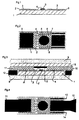
- an HL switch chip 5 (only that Silicon platelets) used.
- the chip 5 is on one good heat conductor 6 (preferably copper) applied. Of from there it is connected to the current output pad 2, the PTC elements (ceramics), which are the actual heating output provide, contacted; another connection is made on Control pad 7 and on the diagnostic pad 8, the connection preferably done in bond technique. All of these pads are good Heat conductor, preferably made of copper, to possibly over Dissipate the connecting cables well can.
- the pads are placed on an electrically non-conductive Heat conductor 1, which is preferably made of ceramic, applied.
- a contact material 3 is applied to the pads, which ensures that the thermal and electrical contact resistance to the contact strip 10, the battery exclusion leads, 11, which leads to the heating element, 13 (for control pad 7), 14 (for diagnostic pad 8) can be minimized according to.
- FIG. 2 shown as a top view; here the training of the Current output pad 2 reproduced with contact material 3 lying on; the chip 5 is on the output pad 2, the control pad 7 and the diagnostic pad 8, which in turn are each covered with contact material 3.
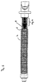
- Fig. 5 shows schematically an embodiment of a Air heater according to the invention again, the inventive modular unit within the aluminum tube 9 arranged at its connection-side area and directly connected to the adjacent PTC heating elements 15 is; the heating output of the HL switch module and PTC elements 15 is dissipated to the environment via fins 16.
Landscapes
- Chemical & Material Sciences (AREA)
- Engineering & Computer Science (AREA)
- Ceramic Engineering (AREA)
- Air-Conditioning For Vehicles (AREA)
- Resistance Heating (AREA)
- Direct Air Heating By Heater Or Combustion Gas (AREA)
- Thermistors And Varistors (AREA)
- Amplifiers (AREA)
- Transition And Organic Metals Composition Catalysts For Addition Polymerization (AREA)
- Bipolar Transistors (AREA)
Description
Aufgabe der Erfindung ist es, unter Umgehung der aufgezeigten Nachteile Luftzuheizer zur Verfügung zu stellen, bei denen der Wärmeübergangswiderstand zwischen HL-Schalter und Kühlmedium verbessert, d.h. erniedrigt wird, mit dem Ziel, leistungsschwächere HL-Schalter einsetzen zu können.
Claims (4)
- Luftzuheizer mit PTC-Heizelement mit Halbleiterschalter, dadurch gekennzeichnet, daß der gehäuselose Halbleiter-Chip (5) im Heizrohr (9) in unmittelbarer Nachbarschaft der PTC-Heizelemente (15) angeordnet ist.
- Luftzuheizer nach Anspruch 1, dadurch gekennzeichnet, daß die Baueinheit Halbleiter-Schalter-Chip (5), zugehörige Kontaktstreifen (10), (11), (13), (14), Stromausgangspad (2), Steuerpad (7) und Diagnosepad (8) sowie diese einschließende, elektrisch nicht leitende Wärmeleiter (1, 15) aufweist.
- Luftzuheizer nach Anspruch 2, dadurch gekennzeichnet, daß der HL-Schalter-Chip (5) gehäuselos auf einer wärmeleitenden Platte (6) aufgebracht ist; daß der Chip (5) am Stromausgangspad (2), am Steuerpad (7) und am Diagnosepad (8) vorzugsweise in Bond-Technik, angeschlossen ist, wobei die Pads auf einem elektrisch nicht leitendem Wärmeleiter (1), vorzugsweise aus Keramik, gelagert sind, wobei auf den Pads Kontaktwerkstoff (3) aufgebracht ist, auf dem die Kontaktstreifen (11) zum PTC-Heizelement, (10) zur Batterie, (13) des Steuerstreifens und (14) des Diagnosestreifens aufliegen.
- Modulare Baueinheit zur Schaltung von Luftzuheizern, gekennzeichnet dadurch, daß der HL-Schalter-Chip (5) gehäuselos auf einer wärmeleitenden Platte (6) aufgebracht ist; daß der Chip (5) am Stromausgangspad (2), am Steuerpad (7) und am Diagnosepad (8) vorzugsweise in Bond-Technik, angeschlossen ist, wobei die Pads auf einem elektrisch nicht leitendem Wärmeleiter (1), vorzugsweise aus Keramik, gelagert sind, wobei auf den Pads Kontaktwerkstoff (3) aufgebracht ist, auf dem die Kontaktstreifen (11) zum PTC-Heizelement, (10) zur Batterie, (13) des Steuerstreifens und (14) des Diagnosestreifens aufliegen.
Applications Claiming Priority (2)
| Application Number | Priority Date | Filing Date | Title |
|---|---|---|---|
| DE10028446A DE10028446B4 (de) | 2000-06-14 | 2000-06-14 | Elektrische Zusatzheizeinrichtung |
| DE10028446 | 2000-06-14 |
Publications (3)
| Publication Number | Publication Date |
|---|---|
| EP1164816A2 EP1164816A2 (de) | 2001-12-19 |
| EP1164816A3 EP1164816A3 (de) | 2003-11-26 |
| EP1164816B1 true EP1164816B1 (de) | 2004-11-03 |
Family
ID=7645155
Family Applications (1)
| Application Number | Title | Priority Date | Filing Date |
|---|---|---|---|
| EP01112177A Expired - Lifetime EP1164816B1 (de) | 2000-06-14 | 2001-05-17 | Luftzuheizer |
Country Status (7)
| Country | Link |
|---|---|
| US (1) | US6911630B2 (de) |
| EP (1) | EP1164816B1 (de) |
| JP (1) | JP2002061954A (de) |
| KR (1) | KR100810036B1 (de) |
| AT (1) | ATE281750T1 (de) |
| DE (2) | DE10028446B4 (de) |
| ES (1) | ES2231342T3 (de) |
Cited By (1)
| Publication number | Priority date | Publication date | Assignee | Title |
|---|---|---|---|---|
| CN102668691A (zh) * | 2010-03-30 | 2012-09-12 | 贝洱海拉温控系统有限公司 | 特别用于混合动力汽车或电动汽车的电加热系统 |
Families Citing this family (14)
| Publication number | Priority date | Publication date | Assignee | Title |
|---|---|---|---|---|
| DE10102671C2 (de) | 2001-01-17 | 2003-12-24 | Eichenauer Heizelemente Gmbh | Elektrische Heizung für ein Kraftfahrzeug |
| DE10208103A1 (de) * | 2002-02-26 | 2003-09-11 | Beru Ag | Elektrische Luftheizungsvorrichtung insbesondere für ein Kraftfahrzeug |
| ITPN20020086A1 (it) * | 2002-11-07 | 2004-05-08 | Irca Spa | Condotto con resistenza elettrica perfezionata e |
| EP1467599B1 (de) | 2003-04-12 | 2008-11-26 | Eichenauer Heizelemente GmbH & Co.KG | Vorrichtung zur Aufnahme von Keramik-Heizelementen und Verfahren zur Herstellung einer solchen |
| EP1651911A4 (de) * | 2003-07-28 | 2010-09-01 | Phillips & Temro Ind Inc | Steuerung für einlassluftheizvorrichtung |
| US8981264B2 (en) | 2006-02-17 | 2015-03-17 | Phillips & Temro Industries Inc. | Solid state switch |
| US8003922B2 (en) * | 2006-02-17 | 2011-08-23 | Phillips & Temro Industries Inc. | Solid state switch with over-temperature and over-current protection |
| TWM324760U (en) * | 2007-02-15 | 2008-01-01 | Hocheng Corp | Indoor air processing device |
| TWI385727B (zh) * | 2009-01-16 | 2013-02-11 | Marketech Int Corp | Applied to the photovoltaic industry, the semiconductor industry, the vacuum environment with high temperature temperature control zone temperature control heater |
| DE102010061550B4 (de) | 2010-12-23 | 2023-06-07 | Webasto Ag | Elektrische Fahrzeugheizvorrichtung |
| DE102015208858A1 (de) | 2015-05-13 | 2016-11-17 | Mahle International Gmbh | Heizmodul zum Beheizen des Fahrzeuginnenraums eines Kraftfahrzeugs |
| US10077745B2 (en) | 2016-05-26 | 2018-09-18 | Phillips & Temro Industries Inc. | Intake air heating system for a vehicle |
| US10221817B2 (en) | 2016-05-26 | 2019-03-05 | Phillips & Temro Industries Inc. | Intake air heating system for a vehicle |
| CN114675625B (zh) * | 2022-03-21 | 2024-11-19 | 潍柴动力股份有限公司 | 一种控制器控制方法及装置 |
Family Cites Families (15)
| Publication number | Priority date | Publication date | Assignee | Title |
|---|---|---|---|---|
| US4196338A (en) * | 1974-04-29 | 1980-04-01 | Saint-Gobain Industries | Electrically heated vehicle window |
| JPS5749355Y2 (de) * | 1976-09-18 | 1982-10-28 | ||
| JPS5548554Y2 (de) * | 1976-09-18 | 1980-11-13 | ||
| US4237366A (en) * | 1979-03-19 | 1980-12-02 | Texas Instruments Incorporated | Heated automobile mirror |
| US4506137A (en) * | 1983-02-18 | 1985-03-19 | Meister Jack B | Temperature responsive control circuit for electric window de-fogger/deicer heater |
| JPH0719645B2 (ja) * | 1984-09-07 | 1995-03-06 | 日本電装株式会社 | 自己温度制御型発熱装置 |
| US5592647A (en) * | 1991-08-26 | 1997-01-07 | Nippon Tungsten Co., Ltd. | PTC panel heater with small rush current characteristic and highly heat insulating region corresponding to heater location to prevent local overheating |
| JPH0555004A (ja) * | 1991-08-26 | 1993-03-05 | Nippon Tungsten Co Ltd | Ptcサーミスタ発熱装置 |
| JPH0620762A (ja) * | 1991-11-20 | 1994-01-28 | Nippon Tungsten Co Ltd | Ptc発熱装置 |
| JP2698318B2 (ja) * | 1993-08-20 | 1998-01-19 | ティーディーケイ株式会社 | ヒータ |
| JP3482000B2 (ja) * | 1994-05-31 | 2003-12-22 | ハリソン東芝ライティング株式会社 | ヒータおよび定着装置ならびに定着装置組込機器 |
| US6410886B1 (en) * | 1997-07-10 | 2002-06-25 | Nitinol Technologies, Inc. | Nitinol heater elements |
| DE19738318C5 (de) * | 1997-09-02 | 2014-10-30 | Behr Gmbh & Co. Kg | Elektrische Heizeinrichtung für ein Kraftfahrzeug |
| DE29719639U1 (de) * | 1997-11-05 | 1998-12-03 | Fritz Eichenauer Gmbh & Co Kg, 76870 Kandel | Vorrichtung zum Beheizen von Innenräumen, insbesondere von Kraftfahrzeugen |
| DE19751423A1 (de) * | 1997-11-20 | 1999-06-02 | Bosch Gmbh Robert | Scheibenheizung |
-
2000
- 2000-06-14 DE DE10028446A patent/DE10028446B4/de not_active Expired - Fee Related
-
2001
- 2001-05-17 ES ES01112177T patent/ES2231342T3/es not_active Expired - Lifetime
- 2001-05-17 DE DE50104355T patent/DE50104355D1/de not_active Expired - Fee Related
- 2001-05-17 AT AT01112177T patent/ATE281750T1/de not_active IP Right Cessation
- 2001-05-17 EP EP01112177A patent/EP1164816B1/de not_active Expired - Lifetime
- 2001-06-08 KR KR1020010032166A patent/KR100810036B1/ko not_active Expired - Fee Related
- 2001-06-12 JP JP2001176661A patent/JP2002061954A/ja active Pending
- 2001-06-13 US US09/879,080 patent/US6911630B2/en not_active Expired - Fee Related
Cited By (2)
| Publication number | Priority date | Publication date | Assignee | Title |
|---|---|---|---|---|
| CN102668691A (zh) * | 2010-03-30 | 2012-09-12 | 贝洱海拉温控系统有限公司 | 特别用于混合动力汽车或电动汽车的电加热系统 |
| CN102668691B (zh) * | 2010-03-30 | 2016-02-03 | 贝洱海拉温控系统有限公司 | 特别用于混合动力汽车或电动汽车的电加热系统 |
Also Published As
| Publication number | Publication date |
|---|---|
| KR100810036B1 (ko) | 2008-03-05 |
| KR20010112589A (ko) | 2001-12-20 |
| ATE281750T1 (de) | 2004-11-15 |
| DE50104355D1 (de) | 2004-12-09 |
| JP2002061954A (ja) | 2002-02-28 |
| US6911630B2 (en) | 2005-06-28 |
| US20010052518A1 (en) | 2001-12-20 |
| DE10028446B4 (de) | 2006-03-30 |
| ES2231342T3 (es) | 2005-05-16 |
| EP1164816A2 (de) | 2001-12-19 |
| DE10028446A1 (de) | 2002-01-03 |
| EP1164816A3 (de) | 2003-11-26 |
Similar Documents
| Publication | Publication Date | Title |
|---|---|---|
| DE10028446B4 (de) | Elektrische Zusatzheizeinrichtung | |
| EP1532723B1 (de) | Anordnung zur unterbringung der leistungs- und steuerelektronik eines elektromotors | |
| EP1390219B1 (de) | Elektrische heizung für ein kraftfahrzeug | |
| DE60212481T2 (de) | Elektrische Energieverteiler für ein Fahrzeug | |
| EP2478556B1 (de) | Elektronische vorrichtung zum schalten von strömen | |
| EP0841842B1 (de) | Steuergerät zur Ansteuerung des Elektromotors von Kraftfahrzeugen | |
| EP2190258A1 (de) | Wärmeübertrager | |
| DE102008059947A1 (de) | Batterie mit einer in einem Batteriegehäuse angeordneten Wärmeleitplatte und daran direkt montierten elektronischen Bauelementen zum Temperieren der Batterie | |
| EP0935818B1 (de) | Elektronisches steuergerät | |
| EP2334161A2 (de) | Steuergerät | |
| DE102008062514A1 (de) | Halbleitermodul-Montagekonstruktion | |
| DE102020205236A1 (de) | Leistungswandler | |
| WO1999027756A1 (de) | Scheibenheizung | |
| EP1586223B1 (de) | Elektrisches verbindungselement, insbesondere für elektro wer kzeugschalter | |
| DE19522126C2 (de) | Elektronischer Lastschalter für ein Kraftfahrzeug, beispielsweise Blinkgeber | |
| EP0264364B1 (de) | Elektrisches schaltgerät | |
| DE102011076273A1 (de) | Leiterplatte für elektrische Bauelemente und Leiterplattensystem | |
| DE102007055320B3 (de) | Elektrischer Steckkontakt eines elektrischen Antriebssystems | |
| DE102019205772A1 (de) | Leistungsmodul mit gehäusten Leistungshalbleitern zur steuerbaren elektrischen Leistungsversorgung eines Verbrauchers | |
| DE10065857B4 (de) | Wärmeübertragungsanordnung für ein Kuststoffgehäuse elektronischer Baugruppen | |
| WO2016180638A1 (de) | Heizmodul zum beheizen des fahrzeuginnenraums eines kraftfahrzeugs | |
| DE102023111188A1 (de) | Leistungsmodul | |
| DE102019115267A1 (de) | Vorrichtung für eine elektrische Antriebseinheit, elektrische Antriebseinheit sowie Kraftfahrzeug | |
| EP3594556B1 (de) | Led-leuchte für ein fahrzeug und fahrzeug mit einer led-leuchte | |
| EP2293648B1 (de) | Wärmeübertrager |
Legal Events
| Date | Code | Title | Description |
|---|---|---|---|
| PUAI | Public reference made under article 153(3) epc to a published international application that has entered the european phase |
Free format text: ORIGINAL CODE: 0009012 |
|
| AK | Designated contracting states |
Kind code of ref document: A2 Designated state(s): AT BE CH CY DE DK ES FI FR GB GR IE IT LI LU MC NL PT SE TR |
|
| AX | Request for extension of the european patent |
Free format text: AL;LT;LV;MK;RO;SI |
|
| PUAL | Search report despatched |
Free format text: ORIGINAL CODE: 0009013 |
|
| AK | Designated contracting states |
Kind code of ref document: A3 Designated state(s): AT BE CH CY DE DK ES FI FR GB GR IE IT LI LU MC NL PT SE TR |
|
| AX | Request for extension of the european patent |
Extension state: AL LT LV MK RO SI |
|
| 17P | Request for examination filed |
Effective date: 20031223 |
|
| GRAP | Despatch of communication of intention to grant a patent |
Free format text: ORIGINAL CODE: EPIDOSNIGR1 |
|
| GRAS | Grant fee paid |
Free format text: ORIGINAL CODE: EPIDOSNIGR3 |
|
| AKX | Designation fees paid |
Designated state(s): AT BE CH CY DE DK ES FI FR GB GR IE IT LI LU MC NL PT SE TR |
|
| GRAA | (expected) grant |
Free format text: ORIGINAL CODE: 0009210 |
|
| AK | Designated contracting states |
Kind code of ref document: B1 Designated state(s): AT BE CH CY DE DK ES FI FR GB GR IE IT LI LU MC NL PT SE TR |
|
| PG25 | Lapsed in a contracting state [announced via postgrant information from national office to epo] |
Ref country code: FI Free format text: LAPSE BECAUSE OF FAILURE TO SUBMIT A TRANSLATION OF THE DESCRIPTION OR TO PAY THE FEE WITHIN THE PRESCRIBED TIME-LIMIT Effective date: 20041103 Ref country code: TR Free format text: LAPSE BECAUSE OF FAILURE TO SUBMIT A TRANSLATION OF THE DESCRIPTION OR TO PAY THE FEE WITHIN THE PRESCRIBED TIME-LIMIT Effective date: 20041103 Ref country code: IE Free format text: LAPSE BECAUSE OF FAILURE TO SUBMIT A TRANSLATION OF THE DESCRIPTION OR TO PAY THE FEE WITHIN THE PRESCRIBED TIME-LIMIT Effective date: 20041103 Ref country code: NL Free format text: LAPSE BECAUSE OF FAILURE TO SUBMIT A TRANSLATION OF THE DESCRIPTION OR TO PAY THE FEE WITHIN THE PRESCRIBED TIME-LIMIT Effective date: 20041103 |
|
| REG | Reference to a national code |
Ref country code: GB Ref legal event code: FG4D Free format text: NOT ENGLISH |
|
| REG | Reference to a national code |
Ref country code: CH Ref legal event code: EP |
|
| REF | Corresponds to: |
Ref document number: 50104355 Country of ref document: DE Date of ref document: 20041209 Kind code of ref document: P |
|
| REG | Reference to a national code |
Ref country code: IE Ref legal event code: FG4D Free format text: GERMAN |
|
| PG25 | Lapsed in a contracting state [announced via postgrant information from national office to epo] |
Ref country code: GR Free format text: LAPSE BECAUSE OF FAILURE TO SUBMIT A TRANSLATION OF THE DESCRIPTION OR TO PAY THE FEE WITHIN THE PRESCRIBED TIME-LIMIT Effective date: 20050203 Ref country code: DK Free format text: LAPSE BECAUSE OF FAILURE TO SUBMIT A TRANSLATION OF THE DESCRIPTION OR TO PAY THE FEE WITHIN THE PRESCRIBED TIME-LIMIT Effective date: 20050203 |
|
| REG | Reference to a national code |
Ref country code: SE Ref legal event code: TRGR |
|
| NLV1 | Nl: lapsed or annulled due to failure to fulfill the requirements of art. 29p and 29m of the patents act | ||
| GBT | Gb: translation of ep patent filed (gb section 77(6)(a)/1977) |
Effective date: 20050412 |
|
| REG | Reference to a national code |
Ref country code: ES Ref legal event code: FG2A Ref document number: 2231342 Country of ref document: ES Kind code of ref document: T3 |
|
| PG25 | Lapsed in a contracting state [announced via postgrant information from national office to epo] |
Ref country code: IT Free format text: LAPSE BECAUSE OF NON-PAYMENT OF DUE FEES Effective date: 20050517 Ref country code: LU Free format text: LAPSE BECAUSE OF NON-PAYMENT OF DUE FEES Effective date: 20050517 Ref country code: CY Free format text: LAPSE BECAUSE OF FAILURE TO SUBMIT A TRANSLATION OF THE DESCRIPTION OR TO PAY THE FEE WITHIN THE PRESCRIBED TIME-LIMIT Effective date: 20050517 |
|
| PG25 | Lapsed in a contracting state [announced via postgrant information from national office to epo] |
Ref country code: CH Free format text: LAPSE BECAUSE OF NON-PAYMENT OF DUE FEES Effective date: 20050531 Ref country code: LI Free format text: LAPSE BECAUSE OF NON-PAYMENT OF DUE FEES Effective date: 20050531 Ref country code: BE Free format text: LAPSE BECAUSE OF NON-PAYMENT OF DUE FEES Effective date: 20050531 Ref country code: MC Free format text: LAPSE BECAUSE OF NON-PAYMENT OF DUE FEES Effective date: 20050531 |
|
| REG | Reference to a national code |
Ref country code: IE Ref legal event code: FD4D |
|
| PLBE | No opposition filed within time limit |
Free format text: ORIGINAL CODE: 0009261 |
|
| STAA | Information on the status of an ep patent application or granted ep patent |
Free format text: STATUS: NO OPPOSITION FILED WITHIN TIME LIMIT |
|
| ET | Fr: translation filed | ||
| 26N | No opposition filed |
Effective date: 20050804 |
|
| BERE | Be: lapsed |
Owner name: BERU A.G. Effective date: 20050531 |
|
| REG | Reference to a national code |
Ref country code: CH Ref legal event code: PL |
|
| BERE | Be: lapsed |
Owner name: *BERU A.G. Effective date: 20050531 |
|
| PG25 | Lapsed in a contracting state [announced via postgrant information from national office to epo] |
Ref country code: PT Free format text: LAPSE BECAUSE OF NON-PAYMENT OF DUE FEES Effective date: 20050403 |
|
| PGFP | Annual fee paid to national office [announced via postgrant information from national office to epo] |
Ref country code: DE Payment date: 20080530 Year of fee payment: 8 Ref country code: ES Payment date: 20080530 Year of fee payment: 8 |
|
| PGFP | Annual fee paid to national office [announced via postgrant information from national office to epo] |
Ref country code: AT Payment date: 20080508 Year of fee payment: 8 |
|
| PGFP | Annual fee paid to national office [announced via postgrant information from national office to epo] |
Ref country code: SE Payment date: 20080512 Year of fee payment: 8 |
|
| PGFP | Annual fee paid to national office [announced via postgrant information from national office to epo] |
Ref country code: GB Payment date: 20080509 Year of fee payment: 8 |
|
| GBPC | Gb: european patent ceased through non-payment of renewal fee |
Effective date: 20090517 |
|
| PG25 | Lapsed in a contracting state [announced via postgrant information from national office to epo] |
Ref country code: AT Free format text: LAPSE BECAUSE OF NON-PAYMENT OF DUE FEES Effective date: 20090517 |
|
| REG | Reference to a national code |
Ref country code: FR Ref legal event code: ST Effective date: 20100129 |
|
| PG25 | Lapsed in a contracting state [announced via postgrant information from national office to epo] |
Ref country code: FR Free format text: LAPSE BECAUSE OF NON-PAYMENT OF DUE FEES Effective date: 20090602 |
|
| PGFP | Annual fee paid to national office [announced via postgrant information from national office to epo] |
Ref country code: FR Payment date: 20080514 Year of fee payment: 8 Ref country code: IT Payment date: 20080522 Year of fee payment: 8 |
|
| PGRI | Patent reinstated in contracting state [announced from national office to epo] |
Ref country code: IT Effective date: 20091201 |
|
| PG25 | Lapsed in a contracting state [announced via postgrant information from national office to epo] |
Ref country code: GB Free format text: LAPSE BECAUSE OF NON-PAYMENT OF DUE FEES Effective date: 20090517 |
|
| PG25 | Lapsed in a contracting state [announced via postgrant information from national office to epo] |
Ref country code: DE Free format text: LAPSE BECAUSE OF NON-PAYMENT OF DUE FEES Effective date: 20091201 |
|
| REG | Reference to a national code |
Ref country code: ES Ref legal event code: FD2A Effective date: 20090518 |
|
| PG25 | Lapsed in a contracting state [announced via postgrant information from national office to epo] |
Ref country code: ES Free format text: LAPSE BECAUSE OF NON-PAYMENT OF DUE FEES Effective date: 20090518 |
|
| PGRI | Patent reinstated in contracting state [announced from national office to epo] |
Ref country code: IT Effective date: 20091201 |
|
| PG25 | Lapsed in a contracting state [announced via postgrant information from national office to epo] |
Ref country code: SE Free format text: LAPSE BECAUSE OF NON-PAYMENT OF DUE FEES Effective date: 20090518 |