EP1163886A2 - Résectoscope HF - Google Patents
Résectoscope HF Download PDFInfo
- Publication number
- EP1163886A2 EP1163886A2 EP01113968A EP01113968A EP1163886A2 EP 1163886 A2 EP1163886 A2 EP 1163886A2 EP 01113968 A EP01113968 A EP 01113968A EP 01113968 A EP01113968 A EP 01113968A EP 1163886 A2 EP1163886 A2 EP 1163886A2
- Authority
- EP
- European Patent Office
- Prior art keywords
- electrode
- cutting
- insulator body
- instrument
- loop
- Prior art date
- Legal status (The legal status is an assumption and is not a legal conclusion. Google has not performed a legal analysis and makes no representation as to the accuracy of the status listed.)
- Granted
Links
Images


Classifications
-
- A—HUMAN NECESSITIES
- A61—MEDICAL OR VETERINARY SCIENCE; HYGIENE
- A61B—DIAGNOSIS; SURGERY; IDENTIFICATION
- A61B18/00—Surgical instruments, devices or methods for transferring non-mechanical forms of energy to or from the body
- A61B18/04—Surgical instruments, devices or methods for transferring non-mechanical forms of energy to or from the body by heating
- A61B18/12—Surgical instruments, devices or methods for transferring non-mechanical forms of energy to or from the body by heating by passing a current through the tissue to be heated, e.g. high-frequency current
- A61B18/14—Probes or electrodes therefor
- A61B18/149—Probes or electrodes therefor bow shaped or with rotatable body at cantilever end, e.g. for resectoscopes, or coagulating rollers
Definitions
- the invention relates to an HF resectoscopic instrument for cutting Body tissue in a body cavity filled with conductive liquid, e.g. the human bladder, according to the preamble of claim 1.
- conductive liquid e.g. the human bladder
- Such a generic HF resectoscopic instrument is shown in DE-OS-25 21 719, which is considered the closest prior art.
- the Neutral electrode arranged on the sling carrier arm and can with this in the Shaft of a resectoscope can be extended and retracted. That has the advantage, that the distance between the active and neutral electrodes is constant, and thus largely constant current paths are given, so that the cutting effect the cutting electrode with every extended position of the instrument is approximately constant regardless of the degree of extension.
- the neutral electrode is in the liquid at a distance from the body tissue. With tissue contact of the active electrode HF current flows through the body tissue for a short distance, then occurs into the liquid and through the liquid comes back to the neutral electrode.
- Insulator body between the cutting and neutral electrodes is that the direct current flow between the two electrodes is difficult and consequently reduced , which means that a larger proportion of those fed into the HF instrument Current power passes from the cutting electrode into the body tissue and there Cutting effect unfolds. Conversely, this means that with the invention Instrument to achieve the same cutting success less power has to be fed into the known instruments.
- an insulator body between the active electrode and the Arranging the neutral electrode is known from WO 97/24993 known, in Figure 9 an instrument with a rollable spherical vaporization electrode shows which is rotatably attached to a carrier. The axis of rotation the ball is perpendicular to the longitudinal axis of the carrier. At a short distance above the sphere is a hemispherically curved insulator body, too held by the carrier, arranged on the side facing away from the vaporization electrode Side the neutral electrode is arranged. This will reduce it direct current flow between active and neutral electrodes reached. With this Construction of the insulator body is a large part of the surgeon Field of vision covered. This disadvantage is unavoidable with the spherical electrode used.
- the neutral electrode of the bipolar HF instrument could in principle be attached to any one arrange at any point on the sling carrier.
- the neutral electrode distally on the sling carrier is arranged. This has the advantage that the neutral electrode when retracting the Instrument in the shaft tube of the resectoscope not on the one arranged in the shaft tube Observation or lighting optics must be passed, but with a suitable choice of its dimensions distally when retracted lies in front of the optics. It is to avoid electrical flashovers to ensure that there is no contact between the neutral electrode and the optics.
- the isolator body is also distal to the loop carrier is to be arranged in order between its shielding function to be able to meet the electrodes.
- the cutting electrode, the insulator body and the neutral electrode are all arranged on the sling carrier and are held by him.
- the three can be held independently on the loop holder be, e.g. in each case by means of holding arms coming off the loop holder.
- This is but not only complex to manufacture, but also of low stability. It is therefore advantageous according to claim 3 that the neutral electrode directly on the side of the insulator body facing away from the cutting electrode is attached.
- the insulator body thus carries the neutral electrode and gives it stability. Further this improves the shielding geometry.
- the shape of the neutral electrode is largely arbitrary. But it is according to claim 4 preferred that the neutral electrode is attached to the insulator body is what gives it a better grip. Furthermore, the flat Formation of the neutral electrode has the advantage that that of the cutting electrode Current flowing into the tissue and flowing back from there to the neutral electrode enter the neutral electrode over a large area and therefore with a low current density can. Conversely, this also means that in the event of accidental contact flat neutral electrode with body tissue has little effect on the same arises. The shielding geometry is also further improved.
- the stability of the arrangement of the neutral electrode and the shielding geometry can be further improved in that the neutral electrode according to claim 5 is embedded in the insulator body. It also ensures that the Neutral electrode when it is inserted into the resectoscope, not when it is conductive Can come into contact with the shaft or the optics.
- the insulator body can e.g. be designed as a flat plate. However, it is According to claim 7 advantageous that the insulator body opposite to Cutting electrode is curved. With the curvature the view becomes of the surgeon through the insulator body and the cutting electrode advantageously improved and the electrode can also be easier when retracting be guided over the optics of the resectoscope, especially with one Optics arranged eccentrically above the central axis of the resectoscope.
- the loop holder holding the cutting electrode can e.g. trained with one arm his. In such a case, one also speaks of single-strand electrodes.
- the sling carrier bifurcates into two towards the distal end parallel rods, between which inclined to the longitudinal axis of the sling carrier essentially semicircular, also referred to as the cutting loop Cutting electrode is held.
- the loop level is generally approximate perpendicular to the longitudinal axis of the sling carrier.
- the invention is based on that not limited, but also includes inclination angles deviating from 90 °.
- the Insulator body attaches distally to both rods.
- the insulator body ensures this for good mechanical stability of the distal area of the HF resectoscopic Instruments.
- the insulator body is also preferred for bifurcated ones Loop carriers opposite to the cutting electrode carried by the rods curved. In this way, remains between the cutting electrode and Isolator body a free central area through which an undisturbed observation the surgical field is possible by the surgeon.
- the axis projection of the cutting electrode along with that of the curved insulator with the one placed thereon Neutral electrode essentially forms a circle. It is understood that the diameter of this circle is slightly smaller than the inside diameter of the Shaft tube of the resectoscope has to be. It is also understood that at Resectoscopes with an oval cross-section of the shaft tube also include the above Axial projection should have an oval character.
- the insulator body in one piece from one opposite to the cutting electrode curved part and the course the cutting electrode following distal to this part is arranged so that the insulator body itself already essentially forms a ring.
- the invention Electrodes have a long lifespan because of the use of the HF instrument particularly used cutting loop area due to the lower Isolator body part is mechanically stabilized. There are still advantages when assembling the instrument and a cheap shielding of the cutting loop through the insulator body.
- the cutting electrode as in the lower region wire is formed into a plate, the plate on the Outer surface of the part of the insulator body following the course of the cutting electrode is arranged.
- the bottom can of the plate-shaped area cause coagulation, while the Top is shielded by the insulator body.
- the areas of the cutting electrode are shielded by the insulator body, that are not or should not be in tissue contact, is achieved that the direct Current flow between cutting and neutral electrodes effectively reduced becomes.
- Figure 1 shows the distal end region of an HF resectoscopic according to the invention Instrumentes 1 for its intended use As shown in FIGS. 4 to 6, they are interchangeably arranged in a resectoscope attached and supplied with current by an HF generator, not shown becomes.
- the instrument 1 is as shown in Figures 1 and 4 in its entire length pulled through by an inner conductor 2, with the exception of its proximal contact area and its distal area formed as a cutting loop 3 from an insulator sleeve 4 is surrounded, which in turn consists of a dimensionally stable Material manufactured tube 5 runs.
- the distal area to increase mechanical stability and electrical safety e.g. be equipped with a ceramic reinforcement.
- the loop level of the Cutting loop 3 is approximately perpendicular to the longitudinal axis of the instrument 1.
- the loop 3 is therefore located approximately in the middle below the insulator body 7, on its upper side a flat and in the same way as the insulator body 7 cylindrically curved neutral electrode 9 is inserted, which e.g. a metal plate can be.
- the neutral electrode 9 While the insulator body 7 toward the proximal end, the neutral electrode 9 shields, the neutral electrode 9 has one at the distal end of the insulator body 7 uncovered, i.e. exposed area 10.
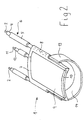
- FIG. 2 shows an embodiment variant of the HF instrument 1, that of the one in FIG. 1 largely shown, the cutting electrode here from a band electrode 13 is formed, the additional on its inner surface an insulating layer 14 may be provided. Otherwise it will match the Parts of the same reference numerals as used in Figure 1.
- FIG. 3 shows an advantageous alternative embodiment of the insulator body 7.
- the Insulator body 7 In addition to the cylindrically upward curved upper part 15, the Insulator body 7, a lower part 16 curved downwards in the opposite direction with the insulator body 7 being made in one piece, e.g. from a ceramic. In the axis projection of the insulator body 7, this essentially forms a ring out.
- the insulator body 7 from FIGS. 1 and 2 it can be seen in FIG. 6 that that this together with the cutting loop 3 also in an axis projection Training ring.
- the static of the distal area of the HF electrode 1 is essentially determined by the one-piece insulator body 7, on which the in its upper region 17 wire-shaped and flat in the lower area in the form of a curved plate 18 trained cutting electrode 3 is attached. This also gives the cutting electrode 3 good stability.
- the body cavity is filled with conductive liquid Cutting electrode 3 in conductive contact with the tissue.
- the current occurs over a small area, i.e. with high current density, in the to be removed Tissue, and thereby unfolds its cutting effect.
- the cutting current passes through the tissue for a short distance on average and flows then, emerging from the tissue over a large area, through the conductive liquid on the top of the insulator body 7 attached neutral electrode 9 back.
- FIG. 3 it can be seen that through the lower part 16 of the insulator body 7 additionally a shielding of the wire-shaped area 17 of the cutting loop 3 towards the proximal side and the area of the plate 18 formed as a plate Cutting loop 3 is carried out upwards.
- FIG. 4 shows an inventive device installed in a commercially available resectoscope 20 Instrument 1 in the embodiment of Figure 1 in the extended Condition, the forward and backward movement of the instrument in axial Direction via a transporter of the resectoscope, not shown, with to which the instrument 1 is connected.
- the resectoscope 20 consists of a Shaft tube 21, in which the optics 22 shown here as eccentrically arranged, to which proximally e.g. connect an eyepiece or imaging device can, and the HF instrument 1 are included.
- the resectoscope 20 designed such that rinsing liquid continuously from the shaft tube 21 can exit and be removed again, e.g. by the shaft as a double shaft with inlet openings for the backflow in its outer wall is trained.
- the associated inflow and reflux connections are located thereby in the proximal area of the resectoscope 20 no longer shown.
- Proximal from the fork 23 is on the tube 5 of the instrument 1 Guide sleeve 24 attached, the optics 22 with little in the installed state Game and slidably encloses it, so that the instrument 1 at axial Movement relative to the optics 22 is kept stabilizing.
- the fork 23 below the optics, but the extend two loop carriers 6 distal from the crotch point 23 to the top to be guided past the optics 22 laterally.
- FIG. 6 is a frontal view of the one with a circular cross section Tip 25 of the resectoscope 20 can be seen.
- the loop support arms 6 carry the cutting loop 3, which is substantially semicircular and at a distance from the wall of the Tip 25 is bent downward.
- the insulator body 7 rests on the loop support arms 6 and runs in the arch above the optics. It's over here see that between the downward curved cutting loop 3 and the Insulator body 7 bent at the top or the neutral electrode arranged thereon 9 an approximately circular free space area remains through which the surgeon over the optics 22 arranged within this window clear view of the Operating field. Illumination light possibly supplied via the optics is neither by the cutting electrode 3, nor by the neutral electrode 9 and the insulator body 7 hindered.
Applications Claiming Priority (2)
| Application Number | Priority Date | Filing Date | Title |
|---|---|---|---|
| DE10028850A DE10028850C1 (de) | 2000-06-16 | 2000-06-16 | HF-resektoskopisches Instrument |
| DE10028850 | 2000-06-16 |
Publications (3)
| Publication Number | Publication Date |
|---|---|
| EP1163886A2 true EP1163886A2 (fr) | 2001-12-19 |
| EP1163886A3 EP1163886A3 (fr) | 2003-11-12 |
| EP1163886B1 EP1163886B1 (fr) | 2006-05-10 |
Family
ID=7645406
Family Applications (1)
| Application Number | Title | Priority Date | Filing Date |
|---|---|---|---|
| EP01113968A Expired - Lifetime EP1163886B1 (fr) | 2000-06-16 | 2001-06-08 | Résectoscope HF |
Country Status (3)
| Country | Link |
|---|---|
| US (1) | US6471701B2 (fr) |
| EP (1) | EP1163886B1 (fr) |
| DE (1) | DE10028850C1 (fr) |
Cited By (5)
| Publication number | Priority date | Publication date | Assignee | Title |
|---|---|---|---|---|
| WO2004052220A1 (fr) | 2002-12-06 | 2004-06-24 | Karl Storz Gmbh & Co. Kg | Instrument medical bipolaire et systeme electrochirurgical comportant un tel instrument |
| EP2842506A1 (fr) | 2013-08-30 | 2015-03-04 | Karl Storz GmbH & Co. KG | Instrument médical et système électrochirurgical |
| DE102018127919A1 (de) * | 2018-11-08 | 2020-05-14 | Karl Storz Se & Co. Kg | Elektrodenanordnung für ein bipolares Resektoskop sowie Resektoskop |
| US11141218B2 (en) | 2017-08-18 | 2021-10-12 | Bowa-Electronic Gmbh & Co. Kg | Bipolar resectoscope |
| DE102020118265A1 (de) | 2020-07-10 | 2022-01-13 | Karl Storz Se & Co. Kg | Medizinisches Instrument und elektrochirurgisches System |
Families Citing this family (27)
| Publication number | Priority date | Publication date | Assignee | Title |
|---|---|---|---|---|
| DE50110328D1 (de) | 2000-08-26 | 2006-08-10 | Winter & Ibe Olympus | Urologisches resektoskop mit einer monopolaren oder bipolaren elektrode |
| WO2003105707A1 (fr) * | 2002-06-18 | 2003-12-24 | オリンパス光学工業株式会社 | Resectoscope |
| DE10324704B4 (de) * | 2003-05-30 | 2008-08-21 | Olympus Winter & Ibe Gmbh | Ureter-Resektoskop |
| DE202004004306U1 (de) * | 2004-03-19 | 2004-05-19 | Select Medizin-Technik Hermann Sutter Gmbh | Bipolare Koagulationselektrode |
| US7118569B2 (en) * | 2004-05-03 | 2006-10-10 | Acmi Corporation | Bipolar resectoscope electrode |
| US20060041252A1 (en) | 2004-08-17 | 2006-02-23 | Odell Roger C | System and method for monitoring electrosurgical instruments |
| US7465302B2 (en) * | 2004-08-17 | 2008-12-16 | Encision, Inc. | System and method for performing an electrosurgical procedure |
| US7422589B2 (en) * | 2004-08-17 | 2008-09-09 | Encision, Inc. | System and method for performing an electrosurgical procedure |
| DE102005057933B4 (de) * | 2005-12-02 | 2015-03-19 | Olympus Winter & Ibe Gmbh | Urologisches Resektoskop mit Isolierkörper am Außenschaft |
| US8177784B2 (en) * | 2006-09-27 | 2012-05-15 | Electromedical Associates, Llc | Electrosurgical device having floating potential electrode and adapted for use with a resectoscope |
| US8500728B2 (en) | 2008-08-18 | 2013-08-06 | Encision, Inc. | Enhanced control systems including flexible shielding and support systems for electrosurgical applications |
| US9833281B2 (en) | 2008-08-18 | 2017-12-05 | Encision Inc. | Enhanced control systems including flexible shielding and support systems for electrosurgical applications |
| US20120059219A1 (en) * | 2009-06-30 | 2012-03-08 | Gyrus Acmi, Inc. | Bipolar resection device having simplified rotational control and better visualization |
| DE102013001156B4 (de) * | 2013-01-24 | 2021-10-14 | Bowa-Electronic Gmbh & Co. Kg | Bipolares Resektoskop |
| US20140236143A1 (en) | 2013-02-19 | 2014-08-21 | Covidien Lp | Electrosurgical electrodes |
| US9918774B2 (en) | 2014-05-12 | 2018-03-20 | Gyrus Acmi, Inc. | Resistively heated electrosurgical device |
| US10813685B2 (en) | 2014-09-25 | 2020-10-27 | Covidien Lp | Single-handed operable surgical instrument including loop electrode with integrated pad electrode |
| US10383682B2 (en) | 2015-08-28 | 2019-08-20 | Covidien Lp | Powered bipolar resectoscope |
| US10869716B2 (en) | 2015-08-28 | 2020-12-22 | Covidien Lp | Powered bipolar resectoscope |
| US11000328B2 (en) | 2016-11-09 | 2021-05-11 | Gyrus Acmi, Inc. | Resistively heated electrosurgical device |
| DE102017115377A1 (de) * | 2017-07-10 | 2019-01-10 | Karl Storz Se & Co. Kg | Arbeitselement eines Resektoskops sowie Resektoskop |
| CN113473930A (zh) * | 2018-12-14 | 2021-10-01 | 奥林巴斯株式会社 | 电极单元以及内窥镜系统 |
| WO2020157803A1 (fr) * | 2019-01-28 | 2020-08-06 | オリンパス株式会社 | Unité d'électrode et système endoscopique |
| DE102019121674A1 (de) | 2019-08-12 | 2021-02-18 | Olympus Winter & Ibe Gmbh | Vor Kurzschluss geschütztes Elektrodeninstrument und Resektoskop |
| US11864818B2 (en) * | 2020-06-12 | 2024-01-09 | Covidien Lp | End effector assembly for bipolar pencil |
| DE102020117810A1 (de) * | 2020-07-07 | 2022-01-13 | Olympus Winter & Ibe Gmbh | Hochfrequenzelektrode zur Verwendung in einem chirurgischen Handgerät, Elektrodeninstrument und Resektoskop |
| CN113749760A (zh) * | 2021-09-02 | 2021-12-07 | 江苏邦士医疗科技有限公司 | 一种膀胱癌切瘤手术用等离子电极 |
Citations (4)
| Publication number | Priority date | Publication date | Assignee | Title |
|---|---|---|---|---|
| US4116198A (en) * | 1975-05-15 | 1978-09-26 | Delma, Elektro Und Medizinische Apparatebaugesellschaft M.B.H. | Electro - surgical device |
| US5196011A (en) * | 1990-10-15 | 1993-03-23 | Olympus Winter & Ibe Gmbh | Cutting electrode for medical resectoscope |
| US5919191A (en) * | 1995-01-30 | 1999-07-06 | Boston Scientific Corporation | Electro-surgical tissue removal |
| US5993445A (en) * | 1995-05-22 | 1999-11-30 | Advanced Closure Systems, Inc. | Resectoscope electrode assembly with simultaneous cutting and coagulation |
Family Cites Families (2)
| Publication number | Priority date | Publication date | Assignee | Title |
|---|---|---|---|---|
| SE404978B (sv) * | 1976-06-22 | 1978-11-06 | Ericsson Telefon Ab L M | Kabelsax |
| US5919189A (en) * | 1996-05-21 | 1999-07-06 | Benderev; Theodore V. | Electrosurgical instrument and method of use |
-
2000
- 2000-06-16 DE DE10028850A patent/DE10028850C1/de not_active Expired - Lifetime
-
2001
- 2001-06-08 EP EP01113968A patent/EP1163886B1/fr not_active Expired - Lifetime
- 2001-06-14 US US09/881,504 patent/US6471701B2/en not_active Expired - Lifetime
Patent Citations (4)
| Publication number | Priority date | Publication date | Assignee | Title |
|---|---|---|---|---|
| US4116198A (en) * | 1975-05-15 | 1978-09-26 | Delma, Elektro Und Medizinische Apparatebaugesellschaft M.B.H. | Electro - surgical device |
| US5196011A (en) * | 1990-10-15 | 1993-03-23 | Olympus Winter & Ibe Gmbh | Cutting electrode for medical resectoscope |
| US5919191A (en) * | 1995-01-30 | 1999-07-06 | Boston Scientific Corporation | Electro-surgical tissue removal |
| US5993445A (en) * | 1995-05-22 | 1999-11-30 | Advanced Closure Systems, Inc. | Resectoscope electrode assembly with simultaneous cutting and coagulation |
Cited By (9)
| Publication number | Priority date | Publication date | Assignee | Title |
|---|---|---|---|---|
| WO2004052220A1 (fr) | 2002-12-06 | 2004-06-24 | Karl Storz Gmbh & Co. Kg | Instrument medical bipolaire et systeme electrochirurgical comportant un tel instrument |
| US7611511B2 (en) | 2002-12-06 | 2009-11-03 | Karl Storz Gmbh & Co. Kg | Bipolar medical instrument and electrosurgical system comprising such an instrument |
| EP2842506A1 (fr) | 2013-08-30 | 2015-03-04 | Karl Storz GmbH & Co. KG | Instrument médical et système électrochirurgical |
| DE102013109505A1 (de) | 2013-08-30 | 2015-03-05 | Karl Storz Gmbh & Co. Kg | Medizinisches Instrument und elektrochirurgisches System |
| US10022184B2 (en) | 2013-08-30 | 2018-07-17 | Karl Storz Se & Co. Kg | Medical instrument and electrosurgical system |
| US11141218B2 (en) | 2017-08-18 | 2021-10-12 | Bowa-Electronic Gmbh & Co. Kg | Bipolar resectoscope |
| DE102018127919A1 (de) * | 2018-11-08 | 2020-05-14 | Karl Storz Se & Co. Kg | Elektrodenanordnung für ein bipolares Resektoskop sowie Resektoskop |
| US11096740B2 (en) | 2018-11-08 | 2021-08-24 | Karl Storz Se & Co. Kg | Electrode arrangement for a bipolar resectoscope, and resectoscope |
| DE102020118265A1 (de) | 2020-07-10 | 2022-01-13 | Karl Storz Se & Co. Kg | Medizinisches Instrument und elektrochirurgisches System |
Also Published As
| Publication number | Publication date |
|---|---|
| DE10028850C1 (de) | 2001-10-31 |
| US20010053908A1 (en) | 2001-12-20 |
| EP1163886B1 (fr) | 2006-05-10 |
| EP1163886A3 (fr) | 2003-11-12 |
| US6471701B2 (en) | 2002-10-29 |
Similar Documents
| Publication | Publication Date | Title |
|---|---|---|
| DE10028850C1 (de) | HF-resektoskopisches Instrument | |
| EP1221903B1 (fr) | Resectoscope urologique avec une electrode monopolaire ou bipolaire | |
| EP0481310B1 (fr) | Electrode de coupe pour résectoscope médical | |
| DE602005001776T2 (de) | Bipolare elektrochirurgische Schlinge | |
| DE10324704B4 (de) | Ureter-Resektoskop | |
| EP0954246B1 (fr) | Dispositif pour la coagulation de tissus biologiques | |
| EP1336384B1 (fr) | Instrument medical bipolaire pour couper des tissues | |
| EP0871405B1 (fr) | Instrument chirurgical bipolaire a haute frequence | |
| DE19943791C2 (de) | Schlingeninstrument für ein Endoskop | |
| DE2525982A1 (de) | Zwei- oder einstielige schneidschlinge fuer resektoskope | |
| EP1107703B1 (fr) | Instrument medical bipolaire servant a couper des tissus | |
| EP1891907B1 (fr) | Dispositif destiné à la résection et/ou l'ablation de tissus organiques à l'aide d'une énergie haute fréquence tout comme résectoscope | |
| EP0536440A1 (fr) | Appareil de chirurgie à H.F. pour couper et coaguler | |
| EP1567079B1 (fr) | Instrument medical bipolaire et systeme electrochirurgical comportant un tel instrument | |
| EP3437581A1 (fr) | Unité d'électrode pour un résectoscope médical | |
| DE102017115377A1 (de) | Arbeitselement eines Resektoskops sowie Resektoskop | |
| DE10028959C1 (de) | Endoskopisches Instrument mit zwei Elektroden | |
| EP3649974B1 (fr) | Agencement d'électrodes pour un résectoscope bipolaire et résectoscope | |
| WO2021130229A1 (fr) | Dispositifs d'énucléation de zones tissulaires intracorporelles | |
| DE4440158C2 (de) | Bipolare Koagulationspinzette mit einer Spülleitung | |
| DE2617556C2 (fr) | ||
| EP3708103B1 (fr) | Instrument à électrodes et résectoscope ayant une fonction de préhension | |
| DE10393537B4 (de) | Urologisches Resektoskop mit drehgesichertem Instrumententräger | |
| DE202017103690U1 (de) | Medizinisches Instrument | |
| DE202006002796U1 (de) | Endoskopische Zange mit drei Gelenken |
Legal Events
| Date | Code | Title | Description |
|---|---|---|---|
| PUAI | Public reference made under article 153(3) epc to a published international application that has entered the european phase |
Free format text: ORIGINAL CODE: 0009012 |
|
| AK | Designated contracting states |
Kind code of ref document: A2 Designated state(s): AT BE CH CY DE DK ES FI FR GB GR IE IT LI LU MC NL PT SE TR |
|
| AX | Request for extension of the european patent |
Free format text: AL;LT;LV;MK;RO;SI |
|
| PUAL | Search report despatched |
Free format text: ORIGINAL CODE: 0009013 |
|
| AK | Designated contracting states |
Kind code of ref document: A3 Designated state(s): AT BE CH CY DE DK ES FI FR GB GR IE IT LI LU MC NL PT SE TR |
|
| AX | Request for extension of the european patent |
Extension state: AL LT LV MK RO SI |
|
| RIC1 | Information provided on ipc code assigned before grant |
Ipc: 7A 61B 18/14 A Ipc: 7A 61B 18/16 B |
|
| 17P | Request for examination filed |
Effective date: 20031212 |
|
| AKX | Designation fees paid |
Designated state(s): FR GB |
|
| REG | Reference to a national code |
Ref country code: DE Ref legal event code: 8566 |
|
| 17Q | First examination report despatched |
Effective date: 20041014 |
|
| GRAP | Despatch of communication of intention to grant a patent |
Free format text: ORIGINAL CODE: EPIDOSNIGR1 |
|
| GRAS | Grant fee paid |
Free format text: ORIGINAL CODE: EPIDOSNIGR3 |
|
| GRAA | (expected) grant |
Free format text: ORIGINAL CODE: 0009210 |
|
| AK | Designated contracting states |
Kind code of ref document: B1 Designated state(s): FR GB |
|
| REG | Reference to a national code |
Ref country code: GB Ref legal event code: FG4D Free format text: NOT ENGLISH |
|
| GBT | Gb: translation of ep patent filed (gb section 77(6)(a)/1977) |
Effective date: 20060830 |
|
| ET | Fr: translation filed | ||
| PLBE | No opposition filed within time limit |
Free format text: ORIGINAL CODE: 0009261 |
|
| STAA | Information on the status of an ep patent application or granted ep patent |
Free format text: STATUS: NO OPPOSITION FILED WITHIN TIME LIMIT |
|
| 26N | No opposition filed |
Effective date: 20070213 |
|
| REG | Reference to a national code |
Ref country code: FR Ref legal event code: PLFP Year of fee payment: 16 |
|
| REG | Reference to a national code |
Ref country code: FR Ref legal event code: PLFP Year of fee payment: 17 |
|
| PGFP | Annual fee paid to national office [announced via postgrant information from national office to epo] |
Ref country code: GB Payment date: 20170620 Year of fee payment: 17 Ref country code: FR Payment date: 20170621 Year of fee payment: 17 |
|
| GBPC | Gb: european patent ceased through non-payment of renewal fee |
Effective date: 20180608 |
|
| PG25 | Lapsed in a contracting state [announced via postgrant information from national office to epo] |
Ref country code: GB Free format text: LAPSE BECAUSE OF NON-PAYMENT OF DUE FEES Effective date: 20180608 Ref country code: FR Free format text: LAPSE BECAUSE OF NON-PAYMENT OF DUE FEES Effective date: 20180630 |