EP1163886A2 - HF resectoscope - Google Patents
HF resectoscope Download PDFInfo
- Publication number
- EP1163886A2 EP1163886A2 EP01113968A EP01113968A EP1163886A2 EP 1163886 A2 EP1163886 A2 EP 1163886A2 EP 01113968 A EP01113968 A EP 01113968A EP 01113968 A EP01113968 A EP 01113968A EP 1163886 A2 EP1163886 A2 EP 1163886A2
- Authority
- EP
- European Patent Office
- Prior art keywords
- electrode
- cutting
- insulator body
- instrument
- loop
- Prior art date
- Legal status (The legal status is an assumption and is not a legal conclusion. Google has not performed a legal analysis and makes no representation as to the accuracy of the status listed.)
- Granted
Links
Images


Classifications
-
- A—HUMAN NECESSITIES
- A61—MEDICAL OR VETERINARY SCIENCE; HYGIENE
- A61B—DIAGNOSIS; SURGERY; IDENTIFICATION
- A61B18/00—Surgical instruments, devices or methods for transferring non-mechanical forms of energy to or from the body
- A61B18/04—Surgical instruments, devices or methods for transferring non-mechanical forms of energy to or from the body by heating
- A61B18/12—Surgical instruments, devices or methods for transferring non-mechanical forms of energy to or from the body by heating by passing a current through the tissue to be heated, e.g. high-frequency current
- A61B18/14—Probes or electrodes therefor
- A61B18/149—Probes or electrodes therefor bow shaped or with rotatable body at cantilever end, e.g. for resectoscopes, or coagulating rollers
Definitions
- the invention relates to an HF resectoscopic instrument for cutting Body tissue in a body cavity filled with conductive liquid, e.g. the human bladder, according to the preamble of claim 1.
- conductive liquid e.g. the human bladder
- Such a generic HF resectoscopic instrument is shown in DE-OS-25 21 719, which is considered the closest prior art.
- the Neutral electrode arranged on the sling carrier arm and can with this in the Shaft of a resectoscope can be extended and retracted. That has the advantage, that the distance between the active and neutral electrodes is constant, and thus largely constant current paths are given, so that the cutting effect the cutting electrode with every extended position of the instrument is approximately constant regardless of the degree of extension.
- the neutral electrode is in the liquid at a distance from the body tissue. With tissue contact of the active electrode HF current flows through the body tissue for a short distance, then occurs into the liquid and through the liquid comes back to the neutral electrode.
- Insulator body between the cutting and neutral electrodes is that the direct current flow between the two electrodes is difficult and consequently reduced , which means that a larger proportion of those fed into the HF instrument Current power passes from the cutting electrode into the body tissue and there Cutting effect unfolds. Conversely, this means that with the invention Instrument to achieve the same cutting success less power has to be fed into the known instruments.
- an insulator body between the active electrode and the Arranging the neutral electrode is known from WO 97/24993 known, in Figure 9 an instrument with a rollable spherical vaporization electrode shows which is rotatably attached to a carrier. The axis of rotation the ball is perpendicular to the longitudinal axis of the carrier. At a short distance above the sphere is a hemispherically curved insulator body, too held by the carrier, arranged on the side facing away from the vaporization electrode Side the neutral electrode is arranged. This will reduce it direct current flow between active and neutral electrodes reached. With this Construction of the insulator body is a large part of the surgeon Field of vision covered. This disadvantage is unavoidable with the spherical electrode used.
- the neutral electrode of the bipolar HF instrument could in principle be attached to any one arrange at any point on the sling carrier.
- the neutral electrode distally on the sling carrier is arranged. This has the advantage that the neutral electrode when retracting the Instrument in the shaft tube of the resectoscope not on the one arranged in the shaft tube Observation or lighting optics must be passed, but with a suitable choice of its dimensions distally when retracted lies in front of the optics. It is to avoid electrical flashovers to ensure that there is no contact between the neutral electrode and the optics.
- the isolator body is also distal to the loop carrier is to be arranged in order between its shielding function to be able to meet the electrodes.
- the cutting electrode, the insulator body and the neutral electrode are all arranged on the sling carrier and are held by him.
- the three can be held independently on the loop holder be, e.g. in each case by means of holding arms coming off the loop holder.
- This is but not only complex to manufacture, but also of low stability. It is therefore advantageous according to claim 3 that the neutral electrode directly on the side of the insulator body facing away from the cutting electrode is attached.
- the insulator body thus carries the neutral electrode and gives it stability. Further this improves the shielding geometry.
- the shape of the neutral electrode is largely arbitrary. But it is according to claim 4 preferred that the neutral electrode is attached to the insulator body is what gives it a better grip. Furthermore, the flat Formation of the neutral electrode has the advantage that that of the cutting electrode Current flowing into the tissue and flowing back from there to the neutral electrode enter the neutral electrode over a large area and therefore with a low current density can. Conversely, this also means that in the event of accidental contact flat neutral electrode with body tissue has little effect on the same arises. The shielding geometry is also further improved.
- the stability of the arrangement of the neutral electrode and the shielding geometry can be further improved in that the neutral electrode according to claim 5 is embedded in the insulator body. It also ensures that the Neutral electrode when it is inserted into the resectoscope, not when it is conductive Can come into contact with the shaft or the optics.
- the insulator body can e.g. be designed as a flat plate. However, it is According to claim 7 advantageous that the insulator body opposite to Cutting electrode is curved. With the curvature the view becomes of the surgeon through the insulator body and the cutting electrode advantageously improved and the electrode can also be easier when retracting be guided over the optics of the resectoscope, especially with one Optics arranged eccentrically above the central axis of the resectoscope.
- the loop holder holding the cutting electrode can e.g. trained with one arm his. In such a case, one also speaks of single-strand electrodes.
- the sling carrier bifurcates into two towards the distal end parallel rods, between which inclined to the longitudinal axis of the sling carrier essentially semicircular, also referred to as the cutting loop Cutting electrode is held.
- the loop level is generally approximate perpendicular to the longitudinal axis of the sling carrier.
- the invention is based on that not limited, but also includes inclination angles deviating from 90 °.
- the Insulator body attaches distally to both rods.
- the insulator body ensures this for good mechanical stability of the distal area of the HF resectoscopic Instruments.
- the insulator body is also preferred for bifurcated ones Loop carriers opposite to the cutting electrode carried by the rods curved. In this way, remains between the cutting electrode and Isolator body a free central area through which an undisturbed observation the surgical field is possible by the surgeon.
- the axis projection of the cutting electrode along with that of the curved insulator with the one placed thereon Neutral electrode essentially forms a circle. It is understood that the diameter of this circle is slightly smaller than the inside diameter of the Shaft tube of the resectoscope has to be. It is also understood that at Resectoscopes with an oval cross-section of the shaft tube also include the above Axial projection should have an oval character.
- the insulator body in one piece from one opposite to the cutting electrode curved part and the course the cutting electrode following distal to this part is arranged so that the insulator body itself already essentially forms a ring.
- the invention Electrodes have a long lifespan because of the use of the HF instrument particularly used cutting loop area due to the lower Isolator body part is mechanically stabilized. There are still advantages when assembling the instrument and a cheap shielding of the cutting loop through the insulator body.
- the cutting electrode as in the lower region wire is formed into a plate, the plate on the Outer surface of the part of the insulator body following the course of the cutting electrode is arranged.
- the bottom can of the plate-shaped area cause coagulation, while the Top is shielded by the insulator body.
- the areas of the cutting electrode are shielded by the insulator body, that are not or should not be in tissue contact, is achieved that the direct Current flow between cutting and neutral electrodes effectively reduced becomes.
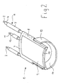
- Figure 1 shows the distal end region of an HF resectoscopic according to the invention Instrumentes 1 for its intended use As shown in FIGS. 4 to 6, they are interchangeably arranged in a resectoscope attached and supplied with current by an HF generator, not shown becomes.
- the instrument 1 is as shown in Figures 1 and 4 in its entire length pulled through by an inner conductor 2, with the exception of its proximal contact area and its distal area formed as a cutting loop 3 from an insulator sleeve 4 is surrounded, which in turn consists of a dimensionally stable Material manufactured tube 5 runs.
- the distal area to increase mechanical stability and electrical safety e.g. be equipped with a ceramic reinforcement.
- the loop level of the Cutting loop 3 is approximately perpendicular to the longitudinal axis of the instrument 1.
- the loop 3 is therefore located approximately in the middle below the insulator body 7, on its upper side a flat and in the same way as the insulator body 7 cylindrically curved neutral electrode 9 is inserted, which e.g. a metal plate can be.
- the neutral electrode 9 While the insulator body 7 toward the proximal end, the neutral electrode 9 shields, the neutral electrode 9 has one at the distal end of the insulator body 7 uncovered, i.e. exposed area 10.
- FIG. 2 shows an embodiment variant of the HF instrument 1, that of the one in FIG. 1 largely shown, the cutting electrode here from a band electrode 13 is formed, the additional on its inner surface an insulating layer 14 may be provided. Otherwise it will match the Parts of the same reference numerals as used in Figure 1.
- FIG. 3 shows an advantageous alternative embodiment of the insulator body 7.
- the Insulator body 7 In addition to the cylindrically upward curved upper part 15, the Insulator body 7, a lower part 16 curved downwards in the opposite direction with the insulator body 7 being made in one piece, e.g. from a ceramic. In the axis projection of the insulator body 7, this essentially forms a ring out.
- the insulator body 7 from FIGS. 1 and 2 it can be seen in FIG. 6 that that this together with the cutting loop 3 also in an axis projection Training ring.
- the static of the distal area of the HF electrode 1 is essentially determined by the one-piece insulator body 7, on which the in its upper region 17 wire-shaped and flat in the lower area in the form of a curved plate 18 trained cutting electrode 3 is attached. This also gives the cutting electrode 3 good stability.
- the body cavity is filled with conductive liquid Cutting electrode 3 in conductive contact with the tissue.
- the current occurs over a small area, i.e. with high current density, in the to be removed Tissue, and thereby unfolds its cutting effect.
- the cutting current passes through the tissue for a short distance on average and flows then, emerging from the tissue over a large area, through the conductive liquid on the top of the insulator body 7 attached neutral electrode 9 back.
- FIG. 3 it can be seen that through the lower part 16 of the insulator body 7 additionally a shielding of the wire-shaped area 17 of the cutting loop 3 towards the proximal side and the area of the plate 18 formed as a plate Cutting loop 3 is carried out upwards.
- FIG. 4 shows an inventive device installed in a commercially available resectoscope 20 Instrument 1 in the embodiment of Figure 1 in the extended Condition, the forward and backward movement of the instrument in axial Direction via a transporter of the resectoscope, not shown, with to which the instrument 1 is connected.
- the resectoscope 20 consists of a Shaft tube 21, in which the optics 22 shown here as eccentrically arranged, to which proximally e.g. connect an eyepiece or imaging device can, and the HF instrument 1 are included.
- the resectoscope 20 designed such that rinsing liquid continuously from the shaft tube 21 can exit and be removed again, e.g. by the shaft as a double shaft with inlet openings for the backflow in its outer wall is trained.
- the associated inflow and reflux connections are located thereby in the proximal area of the resectoscope 20 no longer shown.
- Proximal from the fork 23 is on the tube 5 of the instrument 1 Guide sleeve 24 attached, the optics 22 with little in the installed state Game and slidably encloses it, so that the instrument 1 at axial Movement relative to the optics 22 is kept stabilizing.
- the fork 23 below the optics, but the extend two loop carriers 6 distal from the crotch point 23 to the top to be guided past the optics 22 laterally.
- FIG. 6 is a frontal view of the one with a circular cross section Tip 25 of the resectoscope 20 can be seen.
- the loop support arms 6 carry the cutting loop 3, which is substantially semicircular and at a distance from the wall of the Tip 25 is bent downward.
- the insulator body 7 rests on the loop support arms 6 and runs in the arch above the optics. It's over here see that between the downward curved cutting loop 3 and the Insulator body 7 bent at the top or the neutral electrode arranged thereon 9 an approximately circular free space area remains through which the surgeon over the optics 22 arranged within this window clear view of the Operating field. Illumination light possibly supplied via the optics is neither by the cutting electrode 3, nor by the neutral electrode 9 and the insulator body 7 hindered.
Abstract
Die Erfindung betrifft ein HF-resektoskopisches Instrument zum Schneiden von Körpergewebe in einem mit leitfähiger Flüssigkeit gefüllten Körperhohlraum, mit einem Schlingenträger und einer distal daran angeordneten Schneidelektrode in Form einer Schlinge mit einer zur Längsachse des Schlingenträgers geneigten Schlingenebene, und mit einer am Schlingenträger angeordneten Neutralelektrode, und ist dadurch gekennzeichnet, daß am Schlingenträger zwischen den Elektroden ein Isolatorkörper derart angeordnet ist, daß jede gerade Verbindungslinie zwischen den Elektroden durch den Isolatorkörper verläuft, wobei die Neutralelektrode und der Isolatorkörper in Arbeitsstellung in einem Resektoskop mit in dessen Schaftrohr angeordneter Optik dessen Sicht weitgehend nicht behindernd angeordnet und/oder ausgebildet sind. <IMAGE>The invention relates to an HF resectoscopic instrument for cutting body tissue in a body cavity filled with conductive liquid, with a loop holder and a cutting electrode arranged distally thereon in the form of a loop with a loop plane inclined to the longitudinal axis of the loop holder, and with a neutral electrode arranged on the loop holder. and is characterized in that an insulator body is arranged on the sling carrier between the electrodes in such a way that each straight connecting line between the electrodes runs through the insulator body, the neutral electrode and the insulator body in working position in a resectoscope with optics arranged in its shaft tube largely not having its view are arranged and / or designed to impede. <IMAGE>
Description
Die Erfindung betrifft ein HF-resektoskopisches Instrument zum Schneiden von
Körpergewebe in einem mit leitfähiger Flüssigkeit gefüllten Körperhohlraum,
z.B. der menschlichen Blase, gemäß dem Oberbegriff des Anspruchs 1. Derartige
Instrumente werden zu ihrer bestimmungsgemäßen Verwendung typischerweise
in ein Resektoskop eingebaut.The invention relates to an HF resectoscopic instrument for cutting
Body tissue in a body cavity filled with conductive liquid,
e.g. the human bladder, according to the preamble of
Die klassische Resektoskopie bedient sich der unipolaren bzw. monopolaren Technik. Dabei fließt ein HF-Strom von der Resektionselektrode, der aktiven Elektrode, durch den Körper des Patienten zu einer großflächigen Neutralelektrode, die außen am Patienten, beispielsweise an dessen Oberschenkel, angeordnet ist.Classic resectoscopy uses unipolar or monopolar Technology. An RF current flows from the resection electrode, the active one Electrode, through the patient's body to a large neutral electrode, arranged on the outside of the patient, for example on the thigh is.
Mit dem Stromfluß durch den Körper des Patienten sind aber gewisse Risiken verbunden, die selbst bei sachgemäßer Handhabung des Resektoskopes niemals gänzlich auszuschalten sind. Zu nennen ist in diesem Zusammenhang insbesondere das Auftreten von unkontrollierbaren Leckströmen bzw. vagabundierenden Strömen, die z.B. bei Kontakt des Patienten mit einem metallischen Gegenstand, wie etwa dem Operationstisch, zu schmerzhaften Hautverbrennungen führen können. Weiterhin besteht bei strominduzierten Muskelkontraktionen die Gefahr, daß der Patient unkontrollierte, plötzliche Bewegungen ausführt, die zu Schnittverletzungen durch das resektoskopische Instrument führen können. Es besteht zudem latent die Gefahr, daß Muskel oder Nerven in der Umgebung des Resektionsgebietes zumindest zeitweise durch vagabundierende Ströme geschädigt werden.However, there are certain risks with the flow of current through the patient's body connected, never even with proper handling of the resectoscope must be switched off completely. In this context, it should be mentioned in particular the occurrence of uncontrollable leakage currents or stray Currents e.g. when the patient comes into contact with a metallic object, such as the operating table, cause painful skin burns can. Furthermore, there is a risk of current-induced muscle contractions that the patient makes uncontrolled, sudden movements that lead to cuts can lead through the resectoscopic instrument. It exists in addition, there is a latent risk of muscle or nerves in the vicinity of the resection area are at least temporarily damaged by stray currents.
Die oben genannten Risiken lassen sich bei Anwendung bipolarer Techniken weitestgehend ausschalten. Diesen ist gemein, daß nicht nur die Aktivelektrode, sondern auch die Neutralelektrode in den Körper des Patienten eingebracht wird, so daß der HF-Strom nur zwischen den beiden Elektroden des Instruments fließt, nicht aber, oder nur über definierte kurze Strecken, durch den Körper des Patienten.The above risks can be avoided when using bipolar techniques switch off as far as possible. These have in common that not only the active electrode, but also the neutral electrode is inserted into the patient’s body, so that the RF current only flows between the two electrodes of the instrument, but not, or only over defined short distances, through the patient's body.
Ein solches gattungsgemäßes HF-resektoskopisches Instrument zeigt die DE-OS-25 21 719, die als nächstliegender Stand der Technik angesehen wird. Dort ist die Neutralelektrode am Schlingenträgerarm angeordnet und kann mit diesem in den Schaft eines Resektoskopes ein- und ausgefahren werden. Das hat den Vorteil, daß der Abstand zwischen Aktiv- und Neutralelektrode gleichbleibend ist, und damit weitgehend gleichbleibende Stromwege gegeben sind, so daß die Schneidwirkung der Schneidelektrode bei jeder ausgefahrenen Stellung des Instrumentes unabhängig vom Grad des Ausfahrens näherungsweise konstant ist.Such a generic HF resectoscopic instrument is shown in DE-OS-25 21 719, which is considered the closest prior art. There is the Neutral electrode arranged on the sling carrier arm and can with this in the Shaft of a resectoscope can be extended and retracted. That has the advantage, that the distance between the active and neutral electrodes is constant, and thus largely constant current paths are given, so that the cutting effect the cutting electrode with every extended position of the instrument is approximately constant regardless of the degree of extension.
Bei diesen gattungsgemäßen Instrumenten befindet sich die Neutralelektrode in der Flüssigkeit in Abstand zum Körpergewebe. Bei Gewebekontakt der Aktivelektrode fließt HF-Strom eine kurze Strecke durch das Körpergewebe, tritt dann in die Flüssigkeit aus und gelangt durch die Flüssigkeit zurück zur Neutralelektrode. With these generic instruments, the neutral electrode is in the liquid at a distance from the body tissue. With tissue contact of the active electrode HF current flows through the body tissue for a short distance, then occurs into the liquid and through the liquid comes back to the neutral electrode.
Probleme bei der bipolaren Technik bereiten allerdings die Stromverluste, die durch den direkten Stromfluß durch die gut leitende Flüssigkeit zwischen Aktiv-und Neutralelektrode ohne Durchgang durch das Körpergewebe zustande kommen. In der Konsequenz führt deshalb nur ein Teil des in das HF-Instrument eingespeisten Stromes zu einer Schneidwirkung der Aktivelektrode, namentlich der Anteil, der von der Aktivelektrode in das Körpergewebe übergeht, und von dort zur Neutralelektrode zurückfließt.Problems with bipolar technology, however, are caused by the power losses through the direct current flow through the highly conductive liquid between active and Neutral electrode come about without passage through the body tissue. As a consequence, only a portion of what is fed into the HF instrument leads Current to a cutting effect of the active electrode, namely the Proportion that passes from the active electrode into the body tissue and from there flows back to the neutral electrode.
Diese Stromverluste treten verstärkt insbesondere dann auf, wenn in Körperhohlräumen gearbeitet wird, in denen sich eine besonders gut leitende Flüssigkeit befindet, z.B. wenn während der Resektion mit einer elektrolytreichen z.B. isotonischen Spülflüssigkeit gespült wird. In diesen Fällen wird sogar der überwiegende Teil des Stromes direkt von der Schneid- bzw. Aktivelektrode zur Neutralelektrode fließen, ohne Schneidwirkung zu entfalten. Ein Schneiden ist deshalb mit aus dem Stand der Technik bekannten HF-resektoskopischen Instrumenten in mit leitfähiger Flüssigkeit gefüllten Körperhohlräumen nicht oder nicht zufriedenstellend möglich.These losses of current occur particularly when in body cavities working in which there is a particularly highly conductive liquid, e.g. if during the resection with an electrolyte-rich e.g. isotonic Rinsing liquid is rinsed. In these cases, the overwhelming majority Part of the current directly from the cutting or active electrode to the neutral electrode flow without unfolding. Cutting is therefore also out known in the art RF resectoscopic instruments with conductive Fluid-filled body cavities not or not satisfactorily possible.
Diesem Problem wird im Stand der Technik dadurch begegnet, daß beim Spülen in der Regel schlecht leitende Spülflüssigkeiten eingesetzt werden. Wenn man sich aber vor Augen führt, daß bei der Resektion Blutgefäße eröffnet werden, so daß ein Teil der Flüssigkeit unvermeidlich in den Blutkreislauf des Patienten gelangt, und daß dies sich in einem Komplex von Symptomen, auch als TUR-Syndrom bekannt, äußern kann, wie Erbrechen, Herzrhythmusstörungen, Nierenversagen, Schock, so erscheint dies als eine ungeeignete Lösung, zumal die Symptome bei der Verwendung von isotonischen Flüssigkeiten in geringerem Maße bis gar nicht auftreten. This problem is countered in the prior art in that when rinsing poorly conductive rinsing liquids are generally used. If but it becomes clear that blood vessels are opened during the resection, so that part of the liquid inevitably gets into the patient’s bloodstream, and that this is in a complex of symptoms, also called TUR syndrome known to express, such as vomiting, irregular heartbeat, kidney failure, Shock, this appears to be an unsuitable solution, especially the symptoms when using isotonic liquids to a lesser extent until do not occur.
Es ist deshalb die Aufgabe der vorliegenden Erfindung ein HF-resektoskopisches Instrument zur Verfügung zu stellen, das die aufgezeigten Probleme überwindet, und damit für die Resektion von Körpergewebe in einem mit gut leitfähiger Flüssigkeit gefüllten Körperhohlraum optimiert ist.It is therefore the object of the present invention to use an HF resectoscopic To provide a tool that overcomes the problems identified and thus for the resection of body tissue in a well-conductive liquid filled body cavity is optimized.
Diese Aufgabe wird mit den Merkmalen des Anspruchs 1 gelöst.This object is achieved with the features of
Die Wirkung und damit der Vorteil der erfmdungsgemäßen Anordnung eines Isolatorkörpers zwischen Schneid- und Neutralelektrode besteht darin, daß der direkte Stromfluß zwischen den beiden Elektroden erschwert und mithin vermindert wird, wodurch ein größerer Anteil der in das HF-Instrument eingespeisten Stromleistung von der Schneidelektrode in das Körpergewebe übergeht und dort Schneidwirkung entfaltet. Umgekehrt betrachtet bedeutet dies, daß bei dem erfindungsgemäßen Instrument zur Erzielung des gleichen Schneiderfolges gegenüber den bekannten Instrumenten weniger Leistung eingespeist werden muß.The effect and thus the advantage of the arrangement according to the invention Insulator body between the cutting and neutral electrodes is that the direct current flow between the two electrodes is difficult and consequently reduced , which means that a larger proportion of those fed into the HF instrument Current power passes from the cutting electrode into the body tissue and there Cutting effect unfolds. Conversely, this means that with the invention Instrument to achieve the same cutting success less power has to be fed into the known instruments.
Die prinzipielle Idee, einen Isolatorkörper zwischen der Aktivelektrode und der Neutralelektrode anzuordnen, ist aus der nicht gattungsgemäßen WO 97/24993 bekannt, die in Figur 9 ein Instrument mit einer rollbaren kugelförmigen Vaporationselektrode zeigt, die drehbar an einem Träger angebracht ist. Die Drehachse der Kugel steht dabei senkrecht zur Längsachse des Trägers. In geringem Abstand oberhalb der Kugel ist ein hemisphärisch gekrümmter Isolatorkörper, ebenfalls vom Träger gehalten, angeordnet, auf dessen der Vaporationselektrode abgewandten Seite die Neutralelektrode angeordnet ist. Es wird dadurch ein verringerter direkter Stromfluß zwischen Aktiv- und Neutralelektrode erreicht. Mit dieser Konstruktion des Isolatorkörpers wird dem Operateur jedoch ein Großteil des Sichtfeldes verdeckt. Dieser Nachteil ist bei der verwendeten Kugelelektrode unvermeidbar. The basic idea of an insulator body between the active electrode and the Arranging the neutral electrode is known from WO 97/24993 known, in Figure 9 an instrument with a rollable spherical vaporization electrode shows which is rotatably attached to a carrier. The axis of rotation the ball is perpendicular to the longitudinal axis of the carrier. At a short distance above the sphere is a hemispherically curved insulator body, too held by the carrier, arranged on the side facing away from the vaporization electrode Side the neutral electrode is arranged. This will reduce it direct current flow between active and neutral electrodes reached. With this Construction of the insulator body is a large part of the surgeon Field of vision covered. This disadvantage is unavoidable with the spherical electrode used.
Die Neutralelektrode des bipolaren HF-Instrumentes ließe sich prinzipiell an irgendeiner
beliebigen Stelle des Schlingenträgers anordnen. Es ist allerdings gemäß
Anspruch 2 bevorzugt, daß die Neutralelektrode distal am Schlingenträger
angeordnet ist. Dies hat den Vorteil, daß die Neutralelektrode beim Einfahren des
Instrumentes in das Schaftrohr des Resektoskopes nicht an der im Schaftrohr angeordneten
Beobachtungs- bzw. Beleuchtungsoptik vorbeigeführt werden muß,
sondern bei geeigneter Wahl seiner Abmessungen im eingefahrenen Zustand distal
vor der Optik liegt. Es ist dabei zur Vermeidung elektrischer Überschläge
dafür Sorge zu tragen, daß eine Berührung von Neutralelektrode und Optik unterbleibt.
Es versteht sich, daß dabei der Isolatorkörper ebenfalls distal am Schlingenträger
anzuordnen ist, um seine abschirmende Funktion in Anordnung zwischen
den Elektroden erfüllen zu können.The neutral electrode of the bipolar HF instrument could in principle be attached to any one
arrange at any point on the sling carrier. However, it is in
Die Schneidelektrode, der Isolatorkörper und die Neutralelektrode sind allesamt
am Schlingenträger angeordnet und werden von ihm gehalten. In der allgemeinsten
Form können die drei unabhängig voneinander am Schlingenträger gehalten
sein, z.B. jeweils mittels vom Schlingenträger abgehender Haltearme. Dies ist
aber nicht nur in der Herstellung aufwendig, sondern auch von geringer Stabilität.
Es ist deshalb gemäß Anspruch 3 vorteilhaft, daß die Neutralelektrode direkt auf
der der Schneidelektrode abgewandten Seite des Isolatorkörpers angebracht ist.
Der Isolatorkörper trägt somit die Neutralelektrode und gibt ihr Stabilität. Ferner
wird dadurch die Abschirmgeometrie verbessert.The cutting electrode, the insulator body and the neutral electrode are all
arranged on the sling carrier and are held by him. In the most general
Form the three can be held independently on the loop holder
be, e.g. in each case by means of holding arms coming off the loop holder. This is
but not only complex to manufacture, but also of low stability.
It is therefore advantageous according to
Die Form der Neutralelektrode ist weitgehend beliebig. Es ist aber nach Anspruch
4 bevorzugt, daß die Neutralelektrode flächig auf dem Isolatorkörper angebracht
ist, wodurch sie einen besseren Halt erhält. Weiterhin hat die flächige
Ausbildung der Neutralelektrode den Vorteil, daß der von der Schneidelektrode
ins Gewebe fließende und von dort zur Neutralelektrode zurückfließende Strom
großflächig und damit mit geringer Stromdichte in die Neutralelektrode eintreten
kann. Umgekehrt bedeutet dies aber auch, daß bei versehentlichem Kontakt der
flächigen Neutralelektrode mit Körpergewebe nur eine geringe Wirkung auf dasselbe
entsteht. Zusätzlich wird die Abschirmgeometrie weiter verbessert.The shape of the neutral electrode is largely arbitrary. But it is according to
Die Stabilität der Anordnung der Neutralelektrode und die Abschirmgeometrie
läßt sich dadurch weiter verbessern, daß die Neutralelektrode gemäß Anspruch 5
in den Isolatorkörper eingelassen ist. Es ist weiterhin damit sichergestellt, daß die
Neutralelektrode im in das Resektoskop eingefahrenen Zustand nicht in leitenden
Kontakt mit dem Schaft oder der Optik gelangen kann.The stability of the arrangement of the neutral electrode and the shielding geometry
can be further improved in that the neutral electrode according to
Wenn die Neutralelektrode allerdings vollständig in den Isolatorkörper eingelassen ist, ergibt sich das Problem, daß bei Erreichen der Schneidkante des Resektoskopes durch die Schneidelektrode die Neutralelektrode zum einen vom Isolatorkörper und zum anderen vom in der Regel isoliert ausgebildeten distalen Endbereich des Resektoskopschaftes verdeckt wird. Die Folge ist eine Unterbrechung des Stromflusses, so daß die Schneidwirkung abbricht, bevor der abgeschnittene Gewebestreifen an der Schneidkante abgetrennt worden ist.However, if the neutral electrode is completely embedded in the insulator body there is the problem that when the cutting edge of the resectoscope is reached through the cutting electrode the neutral electrode on the one hand from the insulator body and, on the other hand, from the distal end region, which is generally isolated of the resectoscope shaft is covered. The result is an interruption of the current flow so that the cutting action stops before the cut one Tissue strips have been severed at the cutting edge.
Dies läßt sich in einfacher und vorteilhafter Weise gemäß Anspruch 6 dadurch
vermeiden, daß die Neutralelektrode einen distal nicht von dem Isolatorkörper
abgedeckten Bereich aufweist. Dieser Bereich ist auch im eingefahrenen Zustand
bzw. bei Erreichen der Schneidkante des Resektoskopes durch die Schneidelektrode
unverdeckt und damit für den rückfließenden Strom frei zugänglich, so daß
weiterhin der Stromfluß gewährleistet ist, und der Körpergewebestreifen an der
Schneidkante abgetrennt werden kann.This can be done in a simple and advantageous manner according to
Der Isolatorkörper kann z.B. als ebene Platte ausgebildet sein. Es ist allerdings gemäß Anspruch 7 vorteilhaft, daß der Isolatorkörper entgegengesetzt zur Schneidelektrode gekrümmt ausgebildet ist. Mit der Krümmung wird die Sicht des Operateurs durch den Isolatorkörper und die Schneidelektrode hindurch in vorteilhafter Weise verbessert und die Elektrode kann beim Einfahren zudem einfacher über die Optik des Resektoskopes geführt werden, insbesondere bei einer exzentrisch oberhalb der Mittelachse des Resektoskops angeordneten Optik.The insulator body can e.g. be designed as a flat plate. However, it is According to claim 7 advantageous that the insulator body opposite to Cutting electrode is curved. With the curvature the view becomes of the surgeon through the insulator body and the cutting electrode advantageously improved and the electrode can also be easier when retracting be guided over the optics of the resectoscope, especially with one Optics arranged eccentrically above the central axis of the resectoscope.
Der die Schneidelektrode haltende Schlingenträger kann z.B. einarmig ausgebildet sein. In einem solchen Fall spricht man auch von Einstrang-Elektroden. Üblicherweise gabelt sich der Schlingenträger aber zum distalen Ende hin in zwei parallele Stangen, zwischen denen geneigt zur Längsachse des Schlingenträgers im wesentlichen halbkreisförmig die auch als Schneidschlinge bezeichnete Schneidelektrode gehalten ist. Die Schlingenebene steht dabei in der Regel annähernd senkrecht zur Längsachse des Schlingenträgers. Die Erfindung ist aber darauf nicht beschränkt, sondern umfaßt auch von 90° abweichende Neigungswinkel.The loop holder holding the cutting electrode can e.g. trained with one arm his. In such a case, one also speaks of single-strand electrodes. Usually the sling carrier bifurcates into two towards the distal end parallel rods, between which inclined to the longitudinal axis of the sling carrier essentially semicircular, also referred to as the cutting loop Cutting electrode is held. The loop level is generally approximate perpendicular to the longitudinal axis of the sling carrier. The invention is based on that not limited, but also includes inclination angles deviating from 90 °.
Für den Fall gegabelter Schlingenträger wird mit Vorteil vorgeschlagen, daß der Isolatorkörper an beiden Stangen distal ansetzt. Der Isolatorkörper sorgt dadurch für eine gute mechanische Stabilität des distalen Bereiches des HF-resektoskopischen Instrumentes. Bevorzugt ist der Isolatorkörper auch bei gegabelten Schlingenträgern entgegengesetzt zur von den Stangen getragenen Schneidelektrode gekrümmt. Auf diese Weise verbleibt zwischen Schneidelektrode und Isolatorkörper ein freier zentraler Bereich, durch den eine ungestörte Beobachtung des Operationsfeldes durch den Operateur möglich ist.In the case of forked sling carriers, it is advantageously proposed that the Insulator body attaches distally to both rods. The insulator body ensures this for good mechanical stability of the distal area of the HF resectoscopic Instruments. The insulator body is also preferred for bifurcated ones Loop carriers opposite to the cutting electrode carried by the rods curved. In this way, remains between the cutting electrode and Isolator body a free central area through which an undisturbed observation the surgical field is possible by the surgeon.
Weiterhin ist es nach Anspruch 9 vorteilhaft, daß die Achsprojektion der Schneidelektrode
zusammen mit der des gekrümmten Isolators mit der darauf angeordneten
Neutralelektrode im wesentlichen einen Kreis bildet. Es versteht sich, daß
der Durchmesser dieses Kreises geringfügig kleiner als der Innendurchmesser des
Schaftrohres des Resektoskopes zu sein hat. Es versteht sich ebenfalls, daß bei
Resektoskopen mit ovalem Querschnitt des Schaftrohres auch die oben genannte
Achsprojektion ovalen Charakter erhalten sollte. Die Vorteile entsprechen den im
vorherigen Absatz genannten, nämlich insbesondere eine freie Sicht auf das Operationsfeld.Furthermore, it is advantageous according to
Es ist nach Anspruch 10 vorteilhaft, daß der Isolatorkörper einstückig aus einem entgegengesetzt zur Schneidelektrode gekrümmten Teil und einem dem Verlauf der Schneidelektrode folgenden distal zu dieser angeordneten Teil besteht, so daß der Isolatorkörper für sich genommen bereits im wesentlichen einen Ring ausbildet. Dies trägt insbesondere in Verbindung mit der nach Anspruch 11 vorgeschlagenen Befestigung der Schneidelektrode an dem ihr folgenden Teil des Isolatorkörpers zu einer sehr stabilen Konstruktion bei. Die erfindungsgemäßen Elektroden besitzen eine lange Lebensdauer, da der bei Gebrauch des HF-Instrumentes besonders beanspruchte Schneidschlingenbereich durch den unteren Isolatorkörperteil mechanisch stabilisiert wird. Es ergeben sich weiterhin Vorteile bei der Montage des Instrumentes und eine günstige Abschirmung der Schneidschlinge durch den Isolatorkörper.It is advantageous according to claim 10 that the insulator body in one piece from one opposite to the cutting electrode curved part and the course the cutting electrode following distal to this part is arranged so that the insulator body itself already essentially forms a ring. This contributes in particular in connection with that proposed according to claim 11 Attaching the cutting electrode to the part of the insulator body that follows it to a very stable construction. The invention Electrodes have a long lifespan because of the use of the HF instrument particularly used cutting loop area due to the lower Isolator body part is mechanically stabilized. There are still advantages when assembling the instrument and a cheap shielding of the cutting loop through the insulator body.
Es ist nach Anspruch 12 bevorzugt, daß die Schneidelektrode als im unteren Bereich zu einer Platte verbreiterter Draht ausgebildet ist, wobei die Platte auf der Außenfläche des dem Verlauf der Schneidelektrode folgenden Teils des Isolatorkörpers angeordnet ist. Bei dieser mechanisch stabilen Anordnung kann die Unterseite des plattenförmigen Bereiches eine Koagulation bewirken, während die Oberseite durch den Isolatorkörper abgeschirmt ist. Indem also erfindungsgemäß die Bereiche der Schneidelektrode durch den Isolatorkörper abgeschirmt werden, die nicht in Gewebekontakt stehen bzw. stehen sollen, wird erreicht, daß der direkte Stromfluß zwischen Schneid- und Neutralelektrode effektiv weiter verringert wird. It is preferred according to claim 12 that the cutting electrode as in the lower region wire is formed into a plate, the plate on the Outer surface of the part of the insulator body following the course of the cutting electrode is arranged. With this mechanically stable arrangement, the bottom can of the plate-shaped area cause coagulation, while the Top is shielded by the insulator body. So according to the invention the areas of the cutting electrode are shielded by the insulator body, that are not or should not be in tissue contact, is achieved that the direct Current flow between cutting and neutral electrodes effectively reduced becomes.
In den nachfolgenden Zeichnungen, in denen die Erfindung an Hand von Ausführungsbeispielen schematisch dargestellt ist, sind weitere Einzelheiten und Merkmale der Erfindung ersichtlich. Es zeigen:
Figur 1- eine Perspektivansicht des distalen Endbereiches eines erfindungsgemäßen HF-resektoskopischen Instrumentes mit einer Drahtschlinge als Aktivelektrode,
Figur 2- eine Ansicht gemäß Figur 1 des Instrumentes in einer Variante mit einem Band als Aktivelektrode,
Figur 3- eine Ansicht gemäß Figur 2 mit einem alternativen Isolatorkörper und einer Drahtschlinge mit zu einer Platte erweitertem unteren Bereich als Aktivelektrode,
Figur 4- eine Seitenansicht des Instrumentes gemäß Figur 1 im aus dem Schaftrohr eines längsgeschnitten dargestellten Resektoskopes ausgefahrenen Zustand,
Figur 5- eine
Seitenansicht wie Figur 4 im eingefahrenen Zustand, und Figur 6- eine
Frontansicht zu Figur 5.
- Figure 1
- 2 shows a perspective view of the distal end region of an HF resectoscopic instrument according to the invention with a wire loop as an active electrode,
- Figure 2
- 2 shows a view according to FIG. 1 of the instrument in a variant with a band as the active electrode,
- Figure 3
- 2 shows a view according to FIG. 2 with an alternative insulator body and a wire loop with a lower region expanded as a plate as an active electrode,
- Figure 4
- 2 shows a side view of the instrument according to FIG. 1 in the extended state from the shaft tube of a resectoscope shown in longitudinal section,
- Figure 5
- a side view like Figure 4 in the retracted state, and
- Figure 6
- a front view of Figure 5.
Figur 1 zeigt den distalen Endbereich eines erfindungsgemäßen HF-resektoskopischen
Instrumentes 1, das zu seinem bestimmungsgemäßen Gebrauch
wie die Figuren 4 bis 6 zeigen in einem Resektoskop auswechselbar angeordnet
befestigt und von einem nicht gezeigten HF-Generator mit Strom beaufschlagt
wird.Figure 1 shows the distal end region of an HF resectoscopic according to the
Das Instrument 1 ist wie in Figur 1 und 4 dargestellt in seiner gesamten Länge
von einem Innenleiter 2 durchzogen, der mit Ausnahme seines proximalen Kontaktbereiches
und seines distal als Schneidschlinge 3 ausgebildeten Bereichs von
einer Isolatorhülle 4 umgeben ist, die wiederum innerhalb eines aus einem formstabilen
Material hergestellten Rohres 5 verläuft. Zusätzlich kann der distale Bereich
zur Erhöhung der mechanischen Stabilität und der elektrischen Sicherheit
z.B. mit einer Keramik-Verstärkung ausgerüstet sein. Zum distalen Ende hin gabelt
sich das Instrument 1 in zwei weitgehend parallel zueinander verlaufende
Schlingenträgerarme 6, wobei Fig. 1 nur den distalen Abschnitt nach der Gabelung
darstellt.The
Zwischen den Schlingenträgerarmen 6 und von diesen gehalten erstreckt sich ein
nach oben zylindrisch gebogener, flächig ausgebildeter Isolatorkörper 7, durch
den mittels in dessen Flanken ausgebildeter Bohrungen 8 der Innenleiter 2 in
axialer Richtung bis etwa zur halben Länge des Isolatorkörpers 7 verläuft, um
dort auszutreten und in einem nach unten gekrümmten Bogen die Schneidelektrode
in Form einer Schneidschlinge 3 zu bilden, wobei die Schlingenebene der
Schneidschlinge 3 in etwa senkrecht zur Längsachse des Instrumentes 1 steht. Die
Schlinge 3 befindet sich demzufolge etwa mittig unterhalb des Isolatorkörpers 7,
auf dessen Oberseite eine flächige und in gleicher Weise wie der Isolatorkörper 7
zylindrisch gekrümmte Neutralelektrode 9 eingelassen ist, die z.B. eine Metallplatte
sein kann.Extends between the
Während der Isolatorkörper 7 zum proximalen Ende hin die Neutralelektrode 9
abschirmt, weist die Neutralelektrode 9 am distalen Ende einen vom Isolatorkörper
7 unverdeckten, d.h. freiliegenden Bereich 10 auf. Über eine seitlich verlaufende
Leitung 11, die von einer Isolatorhülle 12 umgeben ist, und die z.B. vorteilhaft
durch eines der Gabelrohre isoliert vom Innenleiter 2 geführt sein kann,
steht die Neutralelektrode 7 mit einem Pol des nicht dargestellten HF-Generators
in leitender Verbindung, während die Schneidschlinge 3 über den Innenleiter 2 an
dessen anderen Pol angeschlossen ist.While the
Figur 2 zeigt eine Ausführungsvariante des HF-Instrumentes 1, die der in Fig. 1
gezeigten weitgehend entspricht, wobei die Schneidelektrode hier von einer Bandelektrode
13 gebildet wird, die auf ihrer innenliegenden Fläche zusätzlich mit
einer Isolierschicht 14 versehen sein kann. Es werden ansonsten bei den übereinstimmenden
Teilen dieselben Bezugszeichen wie in Figur 1 verwendet.FIG. 2 shows an embodiment variant of the
Eine vorteilhafte alternative Ausführungsform des Isolatorkörpers 7 zeigt Figur 3.
Zusätzlich zu dem zylindrisch nach oben gekrümmten oberen Teil 15 weist der
Isolatorkörper 7 ein gegensinnig dazu nach unten gekrümmtes unteres Teil 16
auf, wobei der Isolatorkörper 7 einstückig hergestellt ist, z.B. aus einer Keramik.
In Achsprojektion des Isolatorkörpers 7 bildet dieser im wesentlichen einen Ring
aus. Für den Isolatorkörper 7 aus den Figuren 1 und 2 ist in Figur 6 zu erkennen,
daß dieser zusammen mit der Schneidschlinge 3 ebenfalls in Achsprojektion einen
Ring ausbildet.FIG. 3 shows an advantageous alternative embodiment of the
Die Statik des distalen Bereiches der HF-Elektrode 1 wird im wesentlichen von
dem einstückigen Isolatorkörper 7 geprägt, an dem die in ihrem oberen Bereich
17 drahtförmig und im unteren Bereich flächig in Form einer gekrümmten Platte
18 ausgebildete Schneidelektrode 3 befestigt ist. Dadurch erhält auch die Schneidelektrode
3 eine gute Stabilität.The static of the distal area of the
Neben diesen drei beispielhaft gezeigten Formen der Schneidelektrode sind auch weitere im Stand der Technik bekannte Ausbildungen möglich, z.B. eine mit Rillen oder Profil versehene Schneidelektrode. Die Erfindung ist nicht auf eine spezielle Ausführungsform der Schneidelektrode beschränkt.In addition to these three forms of cutting electrode shown by way of example further designs known in the art are possible, e.g. one with Grooved or profiled cutting electrode. The invention is not limited to one special embodiment of the cutting electrode limited.
Beim Einsatz des HF-Instrumentes 1 zum Schneiden von Körpergewebe in einem
mit leitfähiger Flüssigkeit gefüllten Körperhohlraum befindet sich nur die
Schneidelektrode 3 in leitendem Kontakt mit dem Gewebe. An dieser Kontaktstelle
tritt der Strom kleinflächig, d.h. mit hoher Stromdichte, in das zu entfernende
Gewebe ein, und entfaltet dadurch seine Schneidwirkung. Der Schneidstrom
durchläuft eine im Mittel nur kurze Strecke durch das Gewebe und fließt
dann, großflächig aus dem Gewebe austretend, durch die leitende Flüssigkeit zur
auf der Oberseite des Isolatorkörpers 7 angebrachten Neutralelektrode 9 zurück.
Zusätzlich zu diesem Nutzstrom fließt ein Verluststrom ohne Schneidwirkung zu
entfalten durch die Flüssigkeit direkt von der Schneidelektrode 3 zur Neutralelektrode
9, wobei dieser Anteil dadurch niedrig gehalten wird, daß der Isolatorkörper
7 die geradlinigen Verbindungswege zwischen den beiden Elektroden 3
und 9 abschirmt, den Strom also zwingt, einen längeren Weg zurückzulegen und
dadurch quasi den Widerstand in der Flüssigkeit relativ zum Widerstand des
Stromflusses durch das Körpergewebe erhöht. Da der Strom aber dem Weg des
geringsten Widerstandes bevorzugt folgt, bewirkt die Anordnung des Isolatorkörpers
7 einen erhöhten Stromfluß durch das Körpergewebe, bzw. eine Verringerung
des Verluststromes.When using the
Bei Figur 3 ist zu erkennen, daß durch das untere Teil 16 des Isolatorkörpers 7
zusätzlich eine Abschirmung des drahtförmigen Bereiches 17 der Schneidschlinge
3 zur proximalen Seite hin und des als Platte 18 ausgebildeten Bereiches der
Schneidschlinge 3 nach oben hin erfolgt.In FIG. 3 it can be seen that through the
Figur 4 zeigt ein in einem handelsüblichen Resektoskop 20 eingebautes, erfindungsgemäßes
Instrument 1 in der Ausführungsform der Figur 1 im ausgefahrenen
Zustand, wobei die Vor- und Rückbewegung des Instrumentes in axialer
Richtung über einen nicht gezeigten Transporteur des Resektoskopes erfolgt, mit
dem das Instrument 1 verbunden ist. Das Resektoskop 20 besteht aus einem
Schaftrohr 21, in dem die hier als exzentrisch angeordnet dargestellte Optik 22,
an die sich proximal z.B. ein Okular oder ein Bildaufnahmegerät anschließen
kann, und das HF-Instrument 1 aufgenommen sind. Weiterhin ist das Resektoskop
20 derart ausgestaltet, daß Spülflüssigkeit kontinuierlich aus dem Schaftrohr
21 austreten und auch wieder abgeführt werden kann, z.B. indem der Schaft
als Doppelschaft mit Eintrittsöffnungen für den Rückfluß in seiner äußeren Wand
ausgebildet ist. Die zugehörigen Zufluß- und Rückflußanschlüsse befinden sich
dabei im nicht mehr gezeigten proximalen Bereich des Resektoskopes 20.FIG. 4 shows an inventive device installed in a commercially
Proximal von der Gabelungsstelle 23 ist an dem Rohr 5 des Instrumentes 1 eine
Führungshülse 24 befestigt, die im eingebauten Zustand die Optik 22 mit geringem
Spiel und auf ihr gleitbar umschließt, so daß das Instrument 1 bei axialer
Bewegung relativ zur Optik 22 stabilisierend gehalten ist. Im eingebauten Zustand
liegt die Gabelungsstelle 23 unterhalb der Optik, jedoch erstrecken sich die
beiden Schlingenträger 6 distal von der Gabelungsstelle 23 nach schräg oben, um
seitlich an der Optik 22 vorbeigeführt zu werden.Proximal from the
Dies ist in Figur 5 besser zu erkennen, in der das HF-Instrument 1 im eingefahrenen
Zustand gezeigt ist, sowie in der zugehörigen Frontansicht der Figur 6. Die
Schlingenträgerarme 6 verlaufen seitlich an der Optik 22 vorbei. Die Abmessungen
des Instrumentes 1 sind so gewählt, daß es vollständig in das Resektoskop 20
einziehbar ist. Darunter soll verstanden sein, daß der distale Endbereich des HF-Instrumentes
1 im Seitenprofil vollständig vom distalen Schaftbereich des Resektoskopes
20 abgedeckt ist, der als schnabelförmige isolierte Spitze 25 dargestellt
ist. Es ist zu erkennen, daß die Schneidschlinge 3 zumindest bis auf Höhe
der Schneidkante 26 einziehbar ist, um einen Körpergewebestreifen rückziehend
abschneiden zu können. Zwischen der Neutralelektrode 9 und der Optik 22 verbleibt
ein freier Spalt 27. Bis auf den distal von dem Isolatorkörper 7 freigelassenen
Bereich 10 wird die Neutralelektrode von der Resektoskopspitze 25 verdeckt.This can be seen better in FIG. 5, in which the
In Figur 6 ist in einer Frontalansicht die einen kreisförmigen Querschnitt aufweisende
Spitze 25 des Resektoskopes 20 zu erkennen. Seitlich oberhalb der üblicherweise
exzentrisch oberhalb der Mittelachse angeordneten Optik 22, die z.B.
als 12°-Optik ausgebildet ist, tragen die Schlingenträgerarme 6 die Schneidschlinge
3, die im wesentlichen halbkreisförmig und in Abstand zur Wandung der
Spitze 25 nach unten gebogen verläuft. Der Isolatorkörper 7 setzt an den Schlingenträgerarmen
6 an und verläuft im Bogen oberhalb der Optik. Es ist hier zu
sehen, daß zwischen der nach unten gebogenen Schneidschlinge 3 und dem nach
oben gebogenen Isolatorkörper 7 bzw. der darauf angeordneten Neutralelektrode
9 ein etwa kreisrunder freier Raumbereich verbleibt, durch den der Operateur
über die sich innerhalb dieses Fensters angeordnete Optik 22 freie Sicht auf das
Operationsfeld hat. Auch eventuell über die Optik zugeführtes Beleuchtungslicht
wird weder von der Schneidelektrode 3, noch von der Neutralelektrode 9 und
dem Isolatorkörper 7 behindert.FIG. 6 is a frontal view of the one with a circular
In den Zeichnungen sind lediglich gegabelte Ausführungsformen dargestellt, ohne daß dadurch Einstrang-Elektroden ausgeklammert sein sollen. Dies gilt in gleicher Weise für die stets exzentrisch oberhalb der Schaftquerschnittmitte angeordnet dargestellte Optik, die natürlich auch mittig oder unterhalb der Schaftquerschnittmitte angeordnet sein kann, ohne die Erfindung zu verlassen.In the drawings, only forked embodiments are shown without that single-strand electrodes should be excluded. This applies in same way for the always eccentrically arranged above the shaft cross-section center illustrated optics, which of course also in the middle or below the shaft cross-section center can be arranged without leaving the invention.
Claims (12)
Applications Claiming Priority (2)
| Application Number | Priority Date | Filing Date | Title |
|---|---|---|---|
| DE10028850A DE10028850C1 (en) | 2000-06-16 | 2000-06-16 | High-frequency resection instrument, to cut tissue in bladder, has neutral electrode and insulator body arranged in resection scope and cutting electrode formed as loop inclined on support |
| DE10028850 | 2000-06-16 |
Publications (3)
| Publication Number | Publication Date |
|---|---|
| EP1163886A2 true EP1163886A2 (en) | 2001-12-19 |
| EP1163886A3 EP1163886A3 (en) | 2003-11-12 |
| EP1163886B1 EP1163886B1 (en) | 2006-05-10 |
Family
ID=7645406
Family Applications (1)
| Application Number | Title | Priority Date | Filing Date |
|---|---|---|---|
| EP01113968A Expired - Lifetime EP1163886B1 (en) | 2000-06-16 | 2001-06-08 | HF resectoscope |
Country Status (3)
| Country | Link |
|---|---|
| US (1) | US6471701B2 (en) |
| EP (1) | EP1163886B1 (en) |
| DE (1) | DE10028850C1 (en) |
Cited By (5)
| Publication number | Priority date | Publication date | Assignee | Title |
|---|---|---|---|---|
| WO2004052220A1 (en) | 2002-12-06 | 2004-06-24 | Karl Storz Gmbh & Co. Kg | Bipolar medical instrument and electrosurgical system comprising one such instrument |
| EP2842506A1 (en) | 2013-08-30 | 2015-03-04 | Karl Storz GmbH & Co. KG | Medical instrument and electro-surgical system |
| DE102018127919A1 (en) * | 2018-11-08 | 2020-05-14 | Karl Storz Se & Co. Kg | Electrode arrangement for a bipolar resectoscope and resectoscope |
| US11141218B2 (en) | 2017-08-18 | 2021-10-12 | Bowa-Electronic Gmbh & Co. Kg | Bipolar resectoscope |
| DE102020118265A1 (en) | 2020-07-10 | 2022-01-13 | Karl Storz Se & Co. Kg | Medical instrument and electrosurgical system |
Families Citing this family (27)
| Publication number | Priority date | Publication date | Assignee | Title |
|---|---|---|---|---|
| EP1221903B1 (en) | 2000-08-26 | 2006-06-28 | Olympus Winter & Ibe Gmbh | Urological resectoscope with a monopolar or bipolar electrode |
| EP1407718B1 (en) * | 2002-06-18 | 2015-02-25 | Olympus Corporation | Resectoscope |
| DE10324704B4 (en) * | 2003-05-30 | 2008-08-21 | Olympus Winter & Ibe Gmbh | Ureter resectoscope |
| DE202004004306U1 (en) * | 2004-03-19 | 2004-05-19 | Select Medizin-Technik Hermann Sutter Gmbh | Bipolar coagulation electrode |
| US7118569B2 (en) * | 2004-05-03 | 2006-10-10 | Acmi Corporation | Bipolar resectoscope electrode |
| US7422589B2 (en) * | 2004-08-17 | 2008-09-09 | Encision, Inc. | System and method for performing an electrosurgical procedure |
| US7465302B2 (en) * | 2004-08-17 | 2008-12-16 | Encision, Inc. | System and method for performing an electrosurgical procedure |
| US20060041252A1 (en) * | 2004-08-17 | 2006-02-23 | Odell Roger C | System and method for monitoring electrosurgical instruments |
| DE102005057933B4 (en) * | 2005-12-02 | 2015-03-19 | Olympus Winter & Ibe Gmbh | Urological resectoscope with insulating body on the outer shaft |
| US8177784B2 (en) * | 2006-09-27 | 2012-05-15 | Electromedical Associates, Llc | Electrosurgical device having floating potential electrode and adapted for use with a resectoscope |
| US9833281B2 (en) | 2008-08-18 | 2017-12-05 | Encision Inc. | Enhanced control systems including flexible shielding and support systems for electrosurgical applications |
| US8500728B2 (en) | 2008-08-18 | 2013-08-06 | Encision, Inc. | Enhanced control systems including flexible shielding and support systems for electrosurgical applications |
| US20120059219A1 (en) * | 2009-06-30 | 2012-03-08 | Gyrus Acmi, Inc. | Bipolar resection device having simplified rotational control and better visualization |
| DE102013001156B4 (en) * | 2013-01-24 | 2021-10-14 | Bowa-Electronic Gmbh & Co. Kg | Bipolar resectoscope |
| US20140236143A1 (en) | 2013-02-19 | 2014-08-21 | Covidien Lp | Electrosurgical electrodes |
| CN106456236B (en) | 2014-05-12 | 2019-10-29 | 捷锐士阿希迈公司(以奥林巴斯美国外科技术名义) | Electric resistor heating type electrosurgical unit |
| US10813685B2 (en) | 2014-09-25 | 2020-10-27 | Covidien Lp | Single-handed operable surgical instrument including loop electrode with integrated pad electrode |
| US10383682B2 (en) | 2015-08-28 | 2019-08-20 | Covidien Lp | Powered bipolar resectoscope |
| US10869716B2 (en) | 2015-08-28 | 2020-12-22 | Covidien Lp | Powered bipolar resectoscope |
| US11000328B2 (en) | 2016-11-09 | 2021-05-11 | Gyrus Acmi, Inc. | Resistively heated electrosurgical device |
| DE102017115377A1 (en) * | 2017-07-10 | 2019-01-10 | Karl Storz Se & Co. Kg | Working element of a resectoscope and resectoscope |
| JPWO2020121531A1 (en) * | 2018-12-14 | 2021-10-21 | オリンパス株式会社 | Electrode unit and endoscopic system |
| CN113645916A (en) * | 2019-01-28 | 2021-11-12 | 奥林巴斯株式会社 | Electrode unit and endoscope system |
| DE102019121674A1 (en) * | 2019-08-12 | 2021-02-18 | Olympus Winter & Ibe Gmbh | Short-circuit protected electrode instrument and resectoscope |
| US11864818B2 (en) * | 2020-06-12 | 2024-01-09 | Covidien Lp | End effector assembly for bipolar pencil |
| DE102020117810A1 (en) * | 2020-07-07 | 2022-01-13 | Olympus Winter & Ibe Gmbh | High frequency electrode for use in a surgical handheld device, electrode instrument and resectoscope |
| CN113749760A (en) * | 2021-09-02 | 2021-12-07 | 江苏邦士医疗科技有限公司 | Plasma electrode for bladder cancer tumor cutting operation |
Citations (4)
| Publication number | Priority date | Publication date | Assignee | Title |
|---|---|---|---|---|
| US4116198A (en) * | 1975-05-15 | 1978-09-26 | Delma, Elektro Und Medizinische Apparatebaugesellschaft M.B.H. | Electro - surgical device |
| US5196011A (en) * | 1990-10-15 | 1993-03-23 | Olympus Winter & Ibe Gmbh | Cutting electrode for medical resectoscope |
| US5919191A (en) * | 1995-01-30 | 1999-07-06 | Boston Scientific Corporation | Electro-surgical tissue removal |
| US5993445A (en) * | 1995-05-22 | 1999-11-30 | Advanced Closure Systems, Inc. | Resectoscope electrode assembly with simultaneous cutting and coagulation |
Family Cites Families (2)
| Publication number | Priority date | Publication date | Assignee | Title |
|---|---|---|---|---|
| SE404978B (en) * | 1976-06-22 | 1978-11-06 | Ericsson Telefon Ab L M | CABLE SAX |
| US5919189A (en) * | 1996-05-21 | 1999-07-06 | Benderev; Theodore V. | Electrosurgical instrument and method of use |
-
2000
- 2000-06-16 DE DE10028850A patent/DE10028850C1/en not_active Expired - Lifetime
-
2001
- 2001-06-08 EP EP01113968A patent/EP1163886B1/en not_active Expired - Lifetime
- 2001-06-14 US US09/881,504 patent/US6471701B2/en not_active Expired - Lifetime
Patent Citations (4)
| Publication number | Priority date | Publication date | Assignee | Title |
|---|---|---|---|---|
| US4116198A (en) * | 1975-05-15 | 1978-09-26 | Delma, Elektro Und Medizinische Apparatebaugesellschaft M.B.H. | Electro - surgical device |
| US5196011A (en) * | 1990-10-15 | 1993-03-23 | Olympus Winter & Ibe Gmbh | Cutting electrode for medical resectoscope |
| US5919191A (en) * | 1995-01-30 | 1999-07-06 | Boston Scientific Corporation | Electro-surgical tissue removal |
| US5993445A (en) * | 1995-05-22 | 1999-11-30 | Advanced Closure Systems, Inc. | Resectoscope electrode assembly with simultaneous cutting and coagulation |
Cited By (9)
| Publication number | Priority date | Publication date | Assignee | Title |
|---|---|---|---|---|
| WO2004052220A1 (en) | 2002-12-06 | 2004-06-24 | Karl Storz Gmbh & Co. Kg | Bipolar medical instrument and electrosurgical system comprising one such instrument |
| US7611511B2 (en) | 2002-12-06 | 2009-11-03 | Karl Storz Gmbh & Co. Kg | Bipolar medical instrument and electrosurgical system comprising such an instrument |
| EP2842506A1 (en) | 2013-08-30 | 2015-03-04 | Karl Storz GmbH & Co. KG | Medical instrument and electro-surgical system |
| DE102013109505A1 (en) | 2013-08-30 | 2015-03-05 | Karl Storz Gmbh & Co. Kg | Medical instrument and electrosurgical system |
| US10022184B2 (en) | 2013-08-30 | 2018-07-17 | Karl Storz Se & Co. Kg | Medical instrument and electrosurgical system |
| US11141218B2 (en) | 2017-08-18 | 2021-10-12 | Bowa-Electronic Gmbh & Co. Kg | Bipolar resectoscope |
| DE102018127919A1 (en) * | 2018-11-08 | 2020-05-14 | Karl Storz Se & Co. Kg | Electrode arrangement for a bipolar resectoscope and resectoscope |
| US11096740B2 (en) | 2018-11-08 | 2021-08-24 | Karl Storz Se & Co. Kg | Electrode arrangement for a bipolar resectoscope, and resectoscope |
| DE102020118265A1 (en) | 2020-07-10 | 2022-01-13 | Karl Storz Se & Co. Kg | Medical instrument and electrosurgical system |
Also Published As
| Publication number | Publication date |
|---|---|
| EP1163886B1 (en) | 2006-05-10 |
| US20010053908A1 (en) | 2001-12-20 |
| US6471701B2 (en) | 2002-10-29 |
| EP1163886A3 (en) | 2003-11-12 |
| DE10028850C1 (en) | 2001-10-31 |
Similar Documents
| Publication | Publication Date | Title |
|---|---|---|
| DE10028850C1 (en) | High-frequency resection instrument, to cut tissue in bladder, has neutral electrode and insulator body arranged in resection scope and cutting electrode formed as loop inclined on support | |
| EP1221903B1 (en) | Urological resectoscope with a monopolar or bipolar electrode | |
| EP0481310B1 (en) | Cutting electrode for medical resectoscope | |
| DE602005001776T2 (en) | Bipolar electrosurgical sling | |
| DE10324704B4 (en) | Ureter resectoscope | |
| EP0954246B1 (en) | Coagulation device for coagulating biological tissues | |
| EP1336384B1 (en) | Bipolar medical device for cutting tissue | |
| EP0871405B1 (en) | Bipolar high-frequency surgical instrument | |
| DE19943791C2 (en) | Loop instrument for an endoscope | |
| DE2525982A1 (en) | DOUBLE OR SINGLE-END CUTTERING LOOP FOR RESECTOSCOPES | |
| EP1107703B1 (en) | Medical bipolar instrument for cutting tissue | |
| EP1891907B1 (en) | Device for resection and or ablation of organic tissue using high frequency electricity and a resectoscope | |
| EP0536440A1 (en) | H.F. surgical instrument for cutting and coagulating | |
| EP1567079B1 (en) | Bipolar medical instrument and electrosurgical system comprising one such instrument | |
| EP3437581A1 (en) | Electrode unit for a medical resectoscope | |
| DE102017115377A1 (en) | Working element of a resectoscope and resectoscope | |
| DE10028959C1 (en) | Endoscopic instrument has HF electrodes for coagulation or tissue separation positioned in sidewards and distal positions respectively with insulator body between them | |
| EP3649974B1 (en) | Electrode arrangement for a bipolar resectoscope and resectoscope | |
| WO2021130229A1 (en) | Devices for the enucleation of intracorporeal tissue regions | |
| DE4440158C2 (en) | Bipolar coagulation forceps with a irrigation line | |
| DE2617556C2 (en) | ||
| EP3708103B1 (en) | Electrode instrument and resectoscope with gripping function | |
| DE10393537B4 (en) | Urological resectoscope with torsion-protected instrument carrier | |
| DE202017103690U1 (en) | Medical instrument | |
| DE202006002796U1 (en) | Endoscopic instrument with two bipolar front elements, comprising one element designed with fork-shaped rear end |
Legal Events
| Date | Code | Title | Description |
|---|---|---|---|
| PUAI | Public reference made under article 153(3) epc to a published international application that has entered the european phase |
Free format text: ORIGINAL CODE: 0009012 |
|
| AK | Designated contracting states |
Kind code of ref document: A2 Designated state(s): AT BE CH CY DE DK ES FI FR GB GR IE IT LI LU MC NL PT SE TR |
|
| AX | Request for extension of the european patent |
Free format text: AL;LT;LV;MK;RO;SI |
|
| PUAL | Search report despatched |
Free format text: ORIGINAL CODE: 0009013 |
|
| AK | Designated contracting states |
Kind code of ref document: A3 Designated state(s): AT BE CH CY DE DK ES FI FR GB GR IE IT LI LU MC NL PT SE TR |
|
| AX | Request for extension of the european patent |
Extension state: AL LT LV MK RO SI |
|
| RIC1 | Information provided on ipc code assigned before grant |
Ipc: 7A 61B 18/14 A Ipc: 7A 61B 18/16 B |
|
| 17P | Request for examination filed |
Effective date: 20031212 |
|
| AKX | Designation fees paid |
Designated state(s): FR GB |
|
| REG | Reference to a national code |
Ref country code: DE Ref legal event code: 8566 |
|
| 17Q | First examination report despatched |
Effective date: 20041014 |
|
| GRAP | Despatch of communication of intention to grant a patent |
Free format text: ORIGINAL CODE: EPIDOSNIGR1 |
|
| GRAS | Grant fee paid |
Free format text: ORIGINAL CODE: EPIDOSNIGR3 |
|
| GRAA | (expected) grant |
Free format text: ORIGINAL CODE: 0009210 |
|
| AK | Designated contracting states |
Kind code of ref document: B1 Designated state(s): FR GB |
|
| REG | Reference to a national code |
Ref country code: GB Ref legal event code: FG4D Free format text: NOT ENGLISH |
|
| GBT | Gb: translation of ep patent filed (gb section 77(6)(a)/1977) |
Effective date: 20060830 |
|
| ET | Fr: translation filed | ||
| PLBE | No opposition filed within time limit |
Free format text: ORIGINAL CODE: 0009261 |
|
| STAA | Information on the status of an ep patent application or granted ep patent |
Free format text: STATUS: NO OPPOSITION FILED WITHIN TIME LIMIT |
|
| 26N | No opposition filed |
Effective date: 20070213 |
|
| REG | Reference to a national code |
Ref country code: FR Ref legal event code: PLFP Year of fee payment: 16 |
|
| REG | Reference to a national code |
Ref country code: FR Ref legal event code: PLFP Year of fee payment: 17 |
|
| PGFP | Annual fee paid to national office [announced via postgrant information from national office to epo] |
Ref country code: GB Payment date: 20170620 Year of fee payment: 17 Ref country code: FR Payment date: 20170621 Year of fee payment: 17 |
|
| GBPC | Gb: european patent ceased through non-payment of renewal fee |
Effective date: 20180608 |
|
| PG25 | Lapsed in a contracting state [announced via postgrant information from national office to epo] |
Ref country code: GB Free format text: LAPSE BECAUSE OF NON-PAYMENT OF DUE FEES Effective date: 20180608 Ref country code: FR Free format text: LAPSE BECAUSE OF NON-PAYMENT OF DUE FEES Effective date: 20180630 |