EP0536440A1 - Appareil de chirurgie à H.F. pour couper et coaguler - Google Patents
Appareil de chirurgie à H.F. pour couper et coaguler Download PDFInfo
- Publication number
- EP0536440A1 EP0536440A1 EP91117332A EP91117332A EP0536440A1 EP 0536440 A1 EP0536440 A1 EP 0536440A1 EP 91117332 A EP91117332 A EP 91117332A EP 91117332 A EP91117332 A EP 91117332A EP 0536440 A1 EP0536440 A1 EP 0536440A1
- Authority
- EP
- European Patent Office
- Prior art keywords
- sleeve
- electrode
- instrument according
- instrument
- face
- Prior art date
- Legal status (The legal status is an assumption and is not a legal conclusion. Google has not performed a legal analysis and makes no representation as to the accuracy of the status listed.)
- Granted
Links
- 238000005520 cutting process Methods 0.000 title claims abstract description 39
- 230000001112 coagulating effect Effects 0.000 title claims abstract description 7
- 230000007935 neutral effect Effects 0.000 claims abstract description 23
- 239000002184 metal Substances 0.000 claims abstract description 12
- 238000005345 coagulation Methods 0.000 claims description 27
- 230000015271 coagulation Effects 0.000 claims description 27
- 238000000034 method Methods 0.000 claims description 6
- 238000001356 surgical procedure Methods 0.000 claims description 4
- 239000012811 non-conductive material Substances 0.000 claims 1
- 230000002262 irrigation Effects 0.000 description 6
- 238000003973 irrigation Methods 0.000 description 6
- 239000007788 liquid Substances 0.000 description 6
- 238000009413 insulation Methods 0.000 description 5
- 238000002360 preparation method Methods 0.000 description 5
- 210000000664 rectum Anatomy 0.000 description 5
- 201000009030 Carcinoma Diseases 0.000 description 4
- 239000008280 blood Substances 0.000 description 4
- 210000004369 blood Anatomy 0.000 description 4
- 238000011010 flushing procedure Methods 0.000 description 4
- 230000000740 bleeding effect Effects 0.000 description 3
- 238000010292 electrical insulation Methods 0.000 description 3
- 239000007789 gas Substances 0.000 description 3
- 208000004804 Adenomatous Polyps Diseases 0.000 description 2
- 238000004140 cleaning Methods 0.000 description 2
- 230000023597 hemostasis Effects 0.000 description 2
- 239000000779 smoke Substances 0.000 description 2
- 230000003685 thermal hair damage Effects 0.000 description 2
- 208000012260 Accidental injury Diseases 0.000 description 1
- 241000282461 Canis lupus Species 0.000 description 1
- 238000005452 bending Methods 0.000 description 1
- 210000004204 blood vessel Anatomy 0.000 description 1
- 238000002192 cholecystectomy Methods 0.000 description 1
- 230000006378 damage Effects 0.000 description 1
- 230000001419 dependent effect Effects 0.000 description 1
- 238000011161 development Methods 0.000 description 1
- 230000018109 developmental process Effects 0.000 description 1
- 238000006073 displacement reaction Methods 0.000 description 1
- 238000012143 endoscopic resection Methods 0.000 description 1
- 230000002439 hemostatic effect Effects 0.000 description 1
- 208000014674 injury Diseases 0.000 description 1
- 238000002271 resection Methods 0.000 description 1
- 238000002560 therapeutic procedure Methods 0.000 description 1
- 238000012328 transanal endoscopic microsurgery Methods 0.000 description 1
- 208000009540 villous adenoma Diseases 0.000 description 1
Images


Classifications
-
- A—HUMAN NECESSITIES
- A61—MEDICAL OR VETERINARY SCIENCE; HYGIENE
- A61B—DIAGNOSIS; SURGERY; IDENTIFICATION
- A61B18/00—Surgical instruments, devices or methods for transferring non-mechanical forms of energy to or from the body
- A61B18/04—Surgical instruments, devices or methods for transferring non-mechanical forms of energy to or from the body by heating
- A61B18/12—Surgical instruments, devices or methods for transferring non-mechanical forms of energy to or from the body by heating by passing a current through the tissue to be heated, e.g. high-frequency current
- A61B18/14—Probes or electrodes therefor
- A61B18/1485—Probes or electrodes therefor having a short rigid shaft for accessing the inner body through natural openings
-
- A—HUMAN NECESSITIES
- A61—MEDICAL OR VETERINARY SCIENCE; HYGIENE
- A61B—DIAGNOSIS; SURGERY; IDENTIFICATION
- A61B18/00—Surgical instruments, devices or methods for transferring non-mechanical forms of energy to or from the body
- A61B18/04—Surgical instruments, devices or methods for transferring non-mechanical forms of energy to or from the body by heating
- A61B18/12—Surgical instruments, devices or methods for transferring non-mechanical forms of energy to or from the body by heating by passing a current through the tissue to be heated, e.g. high-frequency current
- A61B18/14—Probes or electrodes therefor
- A61B18/1402—Probes for open surgery
-
- A—HUMAN NECESSITIES
- A61—MEDICAL OR VETERINARY SCIENCE; HYGIENE
- A61B—DIAGNOSIS; SURGERY; IDENTIFICATION
- A61B18/00—Surgical instruments, devices or methods for transferring non-mechanical forms of energy to or from the body
- A61B18/04—Surgical instruments, devices or methods for transferring non-mechanical forms of energy to or from the body by heating
- A61B18/12—Surgical instruments, devices or methods for transferring non-mechanical forms of energy to or from the body by heating by passing a current through the tissue to be heated, e.g. high-frequency current
- A61B18/14—Probes or electrodes therefor
- A61B18/148—Probes or electrodes therefor having a short, rigid shaft for accessing the inner body transcutaneously, e.g. for neurosurgery or arthroscopy
-
- A—HUMAN NECESSITIES
- A61—MEDICAL OR VETERINARY SCIENCE; HYGIENE
- A61B—DIAGNOSIS; SURGERY; IDENTIFICATION
- A61B18/00—Surgical instruments, devices or methods for transferring non-mechanical forms of energy to or from the body
- A61B2018/00053—Mechanical features of the instrument of device
- A61B2018/00184—Moving parts
- A61B2018/00196—Moving parts reciprocating lengthwise
-
- A—HUMAN NECESSITIES
- A61—MEDICAL OR VETERINARY SCIENCE; HYGIENE
- A61B—DIAGNOSIS; SURGERY; IDENTIFICATION
- A61B2218/00—Details of surgical instruments, devices or methods for transferring non-mechanical forms of energy to or from the body
- A61B2218/001—Details of surgical instruments, devices or methods for transferring non-mechanical forms of energy to or from the body having means for irrigation and/or aspiration of substances to and/or from the surgical site
- A61B2218/002—Irrigation
- A61B2218/006—Irrigation for smoke evacuation
-
- A—HUMAN NECESSITIES
- A61—MEDICAL OR VETERINARY SCIENCE; HYGIENE
- A61B—DIAGNOSIS; SURGERY; IDENTIFICATION
- A61B2218/00—Details of surgical instruments, devices or methods for transferring non-mechanical forms of energy to or from the body
- A61B2218/001—Details of surgical instruments, devices or methods for transferring non-mechanical forms of energy to or from the body having means for irrigation and/or aspiration of substances to and/or from the surgical site
- A61B2218/007—Aspiration
- A61B2218/008—Aspiration for smoke evacuation
-
- A—HUMAN NECESSITIES
- A61—MEDICAL OR VETERINARY SCIENCE; HYGIENE
- A61M—DEVICES FOR INTRODUCING MEDIA INTO, OR ONTO, THE BODY; DEVICES FOR TRANSDUCING BODY MEDIA OR FOR TAKING MEDIA FROM THE BODY; DEVICES FOR PRODUCING OR ENDING SLEEP OR STUPOR
- A61M3/00—Medical syringes, e.g. enemata; Irrigators
- A61M3/02—Enemata; Irrigators
- A61M3/0279—Cannula; Nozzles; Tips; their connection means
Definitions
- the invention relates to instruments for high-frequency surgery for cutting or coagulating biological tissue with HF current according to the preamble of patent claim 1.
- the instrument known from US-A-4,043,342, Figures 42 to 47 is advantageous for cutting insofar as the HF current does not have to flow through the patient's body, but to the area between the metal needle acting as the cutting electrode and the neutral electrode acting metal sleeve is limited. Since the HF current density within the contact area between the metal sleeve acting as a neutral electrode and the tissue touched by this metal sleeve must not be too large, because otherwise unintentional thermal damage to the tissue in question may occur, the metal needle acting as cutting electrode must be as thin as possible, so that the HF current required for cutting is as small as possible. However, the thinner the metal needle, the smaller the thermal coagulation zone of the cut surfaces and their hemostatic effect.
- This instrument is also not suitable for partial coagulation or hemostasis. If bleeding occurs during cutting, the surgeon must use another instrument suitable for coagulation. This is particularly problematic in endoscopic operations because changing the instruments is time consuming. In the case of heavy bleeding, the view of the bleeding source can also be made difficult or even impossible by the blood flowing out during the change of instruments. In these situations, the surgeon must remove the blood that has flowed out, for example with suction instruments.
- Suction tubes are known for endoscopic operations (e.g. coagulation suction tube with unipolar HF connection, article no. 8840.73 from R. WOLF GmbH, catalog B 608 / VII.88), which are also suitable for coagulation or hemostasis. However, these coagulation suction tubes are not suitable for cutting.
- HF electrodes with metallic preparation hooks are also known for endoscopic operations, which can be used for monopolar cutting and which are equipped with a suction channel for extracting smoke (e.g. Olympus item no. A5601). Since the metallic preparation hook must not be too thin for mechanical preparation, taking into account accidental damage to the tissue to be prepared, the HF current required for cutting with this preparation hook is relatively large. This relatively large HF current must flow from the monopolar preparation hook through the patient's body to a neutral electrode applied to the patient's skin. This is particularly problematic in endoscopic operations insofar as the HF current has to flow through fine tissue structures within the body. In order to avoid unintentional thermal damage to tissue, however, the HF currents required for cutting and / or coagulating should be as small as possible.
- Such an instrument for cutting and / or coagulating with HF current contains an electrically conductive sleeve, from the proximal end of which an electrically conductive needle electrode protrudes as a cutting electrode, which is electrically insulated from the sleeve against this sleeve and is displaceable such that it is complete can be withdrawn into the sleeve.
- the sleeve at its distal end from the patient is equipped with a shaft which consists of a tube and has a length corresponding to the respective application, for example 5 to 20 cm for applications in open surgery and 20 to 50 cm endoscopic application and a diameter of, for example, 5 to 10 millimeters Has .
- the outer surface of the sleeve and the shaft, excluding the end face of the sleeve proximal to the patient is equipped with an electrical insulating layer.
- the electrically non-insulated end face of the sleeve can be used as a coagulation electrode or as a neutral electrode when cutting with the needle electrode.
- the sleeve consists, for example, of a metal tube which is convex, for example hemispherical, on the end surface proximal to the patient, except for a small hole; from which the needle electrode can be pushed out is closed.
- the sleeve and shaft can also be integrally formed from a tube, the diameter of the sleeve and shaft being different or the same.
- the diameter of the sleeve should be as thin as possible with a view of the needle electrode undisturbed.
- the diameter of the shaft should be as large as possible in view of the mechanical stability of the instrument and a suction and / or rinsing channel to be arranged within the shaft.
- suction and / or rinsing channels are arranged, which at the proximal end of the sleeve or the instrument in the suction and / or rinsing holes and at the distal end of the shaft or the patient Instruments end in connections for suction and / or rinsing devices.
- Suction and / or rinsing devices are known devices which are independent of the instrument according to the invention and are therefore not described further here.
- the suction and / or rinsing holes are arranged, for example, in the end face of the sleeve, for which the hole in the end face of the sleeve, through which the needle electrode is pushed out, can preferably also be used when the needle electrode is retracted into the sleeve.
- the needle electrode must be retractable so far into the sleeve that gases and / or liquids can flow unhindered into the suction and / or irrigation channel or irrigation liquids can flow or be sprayed from the suction and / or irrigation channel unhindered.
- suction and / or rinsing holes can be arranged, preferably in the area of the end face of the sleeve, through which gases or flushing liquids are applied in the surgical field when the needle electrode is pulled in or only when the needle electrode is pushed out or gases and / or liquids can be extracted from the surgical field.
- an instrument there are two channels inside and / or outside of the sleeve and / or shaft, which can be used simultaneously or alternately for suction and / or rinsing. Both channels can be performed separately from each other inside and / or outside the shaft and / or the sleeve up to the sleeve and / or up to the suction and / or rinsing holes, where they either open separately into corresponding suction holes and rinsing holes or shortly before
- the patient's proximal end of the instrument unites into at least one common opening through which alternate suction or rinsing is possible.
- the sleeve, the needle electrode, the end face of the sleeve and the suction and / or irrigation channels can be aligned in the same axis as the shaft of the instrument, which is not only when using this instrument in open surgery, but also in some endoscopic applications, such as laparoscopic adhesiolysis. can be useful.
- the degree of freedom of the cut and / or the application of the end face of the sleeve which can be used as a coagulation electrode and / or the spatial orientation of the suction and / or rinsing holes in particular in the case of endoscopic use, e.g. With laparoscopic cholecystectomy, with transanal endoscopic microsurgery or with adhesiolysis, the sleeve including the needle electrode and electrical insulation between the needle electrode and the sleeve, as well as the suction and / or irrigation channels, are in one for shortly before the end of the instrument that is proximal to the patient bent the appropriate use angle.
- the sleeve and / or the shaft of the instrument can be plastically bent so that the surgeon can adapt the instrument to the particular anatomical situation.
- the needle electrode that can be used for cutting can be used manually or by means of an electromagnetic, pneumatic or hydraulic drive to protect against bending or breaking or against accidental injury to the patient or during coagulations for which only the end face of the sleeve is used, or for suction and / or rinsing in the sleeve withdrawn and cut out of the Sleeve are pushed out.
- mechanical devices can also be used, as are known, for example, in a variety of designs for ballpoint pens for latching forward and return or for locking the writing lead.
- the drive for the displacement of the needle electrode that can be used for cutting is arranged, for example, at the distal end of the shaft, as seen from the patient, on which the electrical connections for the needle electrode that can be used for cutting and for the end face of the sleeve that can be used as neutral electrode or coagulation electrode, as well as the connections for Sucking and / or rinsing can be arranged.
- FIG. 1 shows examples of tumorous changes, for example in rectum 1, in which an instrument according to the invention can be used, for example, ulcerating carcinomas 2, villous adenomas 3, polypoid carcinomas 4, sessile adenomatous polyps 5, 6, 7 and / or pedicled adenomatous polyps 8.
- an instrument according to the invention can be used, for example, ulcerating carcinomas 2, villous adenomas 3, polypoid carcinomas 4, sessile adenomatous polyps 5, 6, 7 and / or pedicled adenomatous polyps 8.
- a transanal application of an instrument according to the invention for the operative therapy of a carcinoma in the rectum 1 is shown schematically with reference to FIG. 2 , only the part of the instrument 9 proximal to the patient being shown with a view to a clear representation.
- the instrument 9 is inserted transanal into the rectum 1 .
- the instrument is used by means of a suitable surgical rectoscope, as is shown schematically in FIG. 10.
- the instrument 9 is inserted up to the cartinoma 2 to be removed. To resect the Carcinoma 2, the needle electrode 11 is pushed out of the instrument 9 .
- a blood vessel If a blood vessel is perforated during the resection, it can be coagulated with the end face 14 of the end of the sleeve 12 or the instrument 9 that is proximal to the patient and can be used as a coagulation electrode. During a coagulation, the needle electrode 11 can be withdrawn into the instrument 9 .
- the end of the sleeve 12 or the instrument 9 proximal to the patient is bent against the axis A of the shaft 13 at an angle W suitable for the respective application.
- the shaft 13 and the sleeve 12 are provided with electrical insulation 10 on their outer surface, excluding the convex end face 14 designed as a coagulation electrode.
- the instrument according to the invention can be operated in various ways or connected to a high-frequency generator.
- the needle electrode 11 can be operated as a monopolar cutting electrode, a known neutral electrode, which is customary in monopolar techniques, being applied to the patient's skin in a known manner as the counter electrode.
- the needle electrode 11 is connected to the monopolar, active output socket and the neutral electrode to the neutral output socket of the high-frequency generator.
- the end face 14 of the sleeve 12 can also be used as the counter electrode, as is described in US Pat. No. 4,043,342.
- the needle electrode 11 is connected to the monopolar, active output socket and the end face 14 of the sleeve 12 to the neutral output socket of the high-frequency generator.
- the end face 14 of the sleeve 12 can be operated as a monopolar coagulation electrode, a known neutral electrode, which is customary in monopolar techniques, being applied to the patient's skin in a known manner as the counter electrode.
- the end face 14 of the sleeve 12 serving as a coagulation electrode is connected to the monopolar, active output socket and the neutral electrode applied to the patient's skin is connected to the neutral output socket of the high-frequency generator.
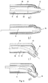
- FIG. 3 the end of an instrument 9 according to the invention proximal to the patient is shown in section, specifically with the needle electrode 11 pushed out for cutting in FIG. 3a and straight with the needle electrode 11 drawn in for coagulation, suction and / or rinsing or in the rest position in FIG. 3b and bent with the needle electrode pushed out for cutting in FIG. 3c and bent with the needle electrode pulled in for coagulation, suction and / or rinsing or in the rest position in FIG. 3d.
- the proximal end of this instrument according to the invention to the patient consists of a metallic, preferably round sleeve 12 which is extended by a preferably round, metallic shaft 13.
- Sleeve 12 and shaft 13 can also be formed in one piece from a metallic tube, as shown in FIG. 3b.
- the shaft 13 can have a length such that the instrument is also suitable for endoscopic applications.
- the sleeve 12 and shaft 13 are provided with an electrical insulating layer 10 on their outer surface excluding the end face 14 of the sleeve 12, which can be used as a coagulation electrode or when cutting with the needle electrode 11 as a neutral electrode.
- a hole 16 is provided in the end face 14 of the sleeve 12, through which the needle electrode 11 can be pushed. The diameter of this hole 16 is so large that the insulation 15 of the needle electrode 11 can be easily pushed through this hole on the one hand and on the other hand so narrow that the needle electrode 11 is guided well by the sleeve 12 without wobbling.
- the inner diameter d H of the sleeve 12 and / or d S of the shaft 13 or the instrument 9 is so large that between the outer diameter d I of the insulation 15 of the needle electrode 11 and the inner diameter d H of the sleeve 12 and d S of the shaft Channel K for suction and / or rinsing is available.
- the outer diameter of the sleeve 12 and the shaft 13 can in principle be the same.
- the proximity of the end face 14 should be as small as possible, for example 3 to 5 millimeters.
- the outer diameter of the sleeve 12 can expediently be reduced in at least one step and / or conically, as shown in FIG. 3, from the outer diameter of the shaft 13 to the diameter of the end face 14.
- the needle electrode 11 is insulated with an electrical insulation 15 against the metallic sleeve 12 and the shaft 13.
- the needle electrode 11 can be retracted into the sleeve 12 to such an extent that the hole 16 in the end face 14 is free for suction and / or rinsing.
- the relatively thin needle 11 In order to ensure that the effective length for cutting the needle electrode 11 which can be pushed out of the end face 14 of the sleeve 12 can be adjusted as precisely and reproducibly as possible, the relatively thin needle 11 must either be guided within the relatively large-volume suction and / or rinsing channel in such a way that it cannot bend within this channel, for example by being supported within the channel K, or it must be reinforced to the diameter d N within the instrument, as shown for example in the exemplary embodiments in FIGS. 3a to 3d.
- FIG. 4 shows a sectional illustration of a second exemplary embodiment of the end of an instrument according to the invention proximal to the patient, specifically with the needle electrode pushed out in FIG. 4a and straight with the needle electrode drawn in in FIG. 4b and bent with the needle electrode pushed out in FIG. 4c and bent with the needle electrode pulled in in FIG. 4d.
- This embodiment differs from the embodiment in FIGS. 3a to 3d by additional holes 17 for suction and / or rinsing in the immediate vicinity of the end face 14 of the sleeve 12, which are preferably arranged radially around the hole 16 in such a way that suction and / or Flushing through these additional holes 17 is also possible if the needle electrode 11 is pushed out of the hole 16 or if the needle electrode is pulled into the sleeve, but the hole 16 is pressed against tissue, as is the case, for example, during coagulation.
- These additional holes 17 can also be used to suck off the steam and / or smoke generated during the cutting and / or coagulation processes.
- Sleeve 12 and shaft 13 can, for example, be assembled from two parts, as shown in FIG. 4a, or they may be formed in one piece from a tube, as shown in FIG. 4b.
- FIG. 5 shows a sectional illustration of a third exemplary embodiment of the end of an instrument according to the invention which is proximal to the patient, specifically with the needle electrode in FIG. 5a pushed out and straight with the drawn-in one 5b and bent with the needle electrode pushed out in FIG. 5c and bent with the needle electrode drawn in in FIG. 5d.
- This embodiment differs from the embodiment of FIGS. 3a to 3d by an additional suction and / or rinsing channel 18, which is inserted, for example, concentrically between the outer diameters of the sleeve 12 and the shaft 13 and the insulation layer 10.
- the distance between the surfaces of the sleeve and the shaft on the one hand and the insulation layer on the other hand can be realized, for example, by knobs or axial profiles on the surfaces of the sleeve and shaft or the inner surface of the insulation 10.
- FIG. 6 shows a sectional illustration of a fourth exemplary embodiment of the end of an instrument according to the invention which is proximal to the patient, specifically with the needle electrode pushed out in FIG. 6a and straight with the needle electrode pulled in in FIG. 6b and bent with the needle electrode pushed out in FIG. 6c and bent with the needle electrode pulled in in FIG. 6d .
- This exemplary embodiment differs from the exemplary embodiment illustrated in FIG. 3 by an additional suction and / or rinsing channel, which is implemented, for example, by a tube 19 which is guided parallel to the sleeve 12 and the shaft 13 and, for example, on the surface of the sleeve and the shaft is soldered on. If this tube 19 is made of metal, it must be equipped with an electrical insulating layer 10 on its surface like the sleeve 12 and the shaft 13. The tube 20 preferably ends shortly before the end face 14 of the sleeve 12.
- FIG. 8a An exemplary embodiment of an instrument according to the invention is shown schematically in FIG .
- a drive 22 for pushing out or pulling in the needle electrode 11 is shown schematically.
- This drive 22 can be implemented, for example, electromagnetically, as shown schematically in FIG. 8a , or pneumatically or hydraulically, as shown schematically in FIG. 8b , or mechanically, as is known, for example, in ballpoint pens for moving out and in and locking the writing lead.
- the connections 23 and 24 are either electrical connections for an electromagnetic drive 22 or compressed air connections for a pneumatic drive 22 or hose connections for a hydraulic drive 22.
- the electrical connections 20 and 21 serve for the HF power supply of the needle electrode 11 and the end face which can be used as a neutral electrode or coagulation electrode 14 of the sleeve 12.
- 25 and 26 are connections for suction and / or rinsing lines to connect the instrument with suction and / or rinsing devices.
- FIG. 9 An instrument according to the invention is shown schematically in FIG. 9 , in which the shaft 13 can be plastically bent by the surgeon so that it can be adapted to the individual or anatomical conditions.
- FIG. 10 shows a schematic representation of a surgical rectoscope for transanal endoscopic resection of tumorous changes in the rectum, through which the instrument according to the invention can be used, for example.
- FIG. 11 shows a sectional illustration of a fifth exemplary embodiment of the end of an instrument according to the invention proximal to the patient, specifically with the needle electrode pushed out in FIG. 11 a and straight with the needle electrode pulled in in FIG. 11 b and bent with the needle electrode pushed out in FIG. 11 c and bent with the needle electrode pulled in in FIG. 11 d.
- two channels K; 19 available, which are inside and / or outside of the shaft 13 and / or the sleeve 12, separated from each other up to the sleeve 12 and / or until just before the suction and / or rinsing opening 16, where they are united within the instrument in the open common opening 16 through which alternately suction or rinsing is possible.
- there is the additional advantage that simple cleaning of the suction channel is possible by closing the common opening 16, for example by pushing out the needle electrode 11, and the flushing liquid within the instrument shortly before the closed opening 16 from the flushing channel 19 into the suction channel K is sucked in to clean the suction channel K of blood and other tissue components, for example.
- the instrument is electrically insulated, for example for endoscopic applications, on its outer surface, with the exception of the end surface 14 which is proximal to the patient and serves as a neutral electrode or coagulation electrode.
Landscapes
- Health & Medical Sciences (AREA)
- Surgery (AREA)
- Engineering & Computer Science (AREA)
- Life Sciences & Earth Sciences (AREA)
- Biomedical Technology (AREA)
- Otolaryngology (AREA)
- Nuclear Medicine, Radiotherapy & Molecular Imaging (AREA)
- Plasma & Fusion (AREA)
- Physics & Mathematics (AREA)
- Heart & Thoracic Surgery (AREA)
- Medical Informatics (AREA)
- Molecular Biology (AREA)
- Animal Behavior & Ethology (AREA)
- General Health & Medical Sciences (AREA)
- Public Health (AREA)
- Veterinary Medicine (AREA)
- Surgical Instruments (AREA)
Priority Applications (2)
| Application Number | Priority Date | Filing Date | Title |
|---|---|---|---|
| EP91117332A EP0536440B1 (fr) | 1991-10-11 | 1991-10-11 | Appareil de chirurgie à H.F. pour couper et coaguler |
| DE59108725T DE59108725D1 (de) | 1991-10-11 | 1991-10-11 | Instrument für die Hochfrequenzchirurgie zum Schneiden oder Koagulieren |
Applications Claiming Priority (1)
| Application Number | Priority Date | Filing Date | Title |
|---|---|---|---|
| EP91117332A EP0536440B1 (fr) | 1991-10-11 | 1991-10-11 | Appareil de chirurgie à H.F. pour couper et coaguler |
Publications (2)
| Publication Number | Publication Date |
|---|---|
| EP0536440A1 true EP0536440A1 (fr) | 1993-04-14 |
| EP0536440B1 EP0536440B1 (fr) | 1997-05-28 |
Family
ID=8207256
Family Applications (1)
| Application Number | Title | Priority Date | Filing Date |
|---|---|---|---|
| EP91117332A Expired - Lifetime EP0536440B1 (fr) | 1991-10-11 | 1991-10-11 | Appareil de chirurgie à H.F. pour couper et coaguler |
Country Status (2)
| Country | Link |
|---|---|
| EP (1) | EP0536440B1 (fr) |
| DE (1) | DE59108725D1 (fr) |
Cited By (22)
| Publication number | Priority date | Publication date | Assignee | Title |
|---|---|---|---|---|
| DE4222769A1 (de) * | 1992-07-10 | 1994-01-13 | Erbe Elektromedizin | Instrument für die Hochfrequenzchirurgie |
| EP0658333A1 (fr) * | 1993-12-17 | 1995-06-21 | United States Surgical Corporation | Instrument électrochirurgical monopolaire |
| ES2076124A1 (es) * | 1993-11-10 | 1995-10-16 | Garcia Manuel Garcia | Aplicador de tampones en endocirugia. |
| GB2269538B (en) * | 1992-08-12 | 1996-10-09 | Vidamed Inc | Medical probe |
| WO1997018766A1 (fr) * | 1995-11-20 | 1997-05-29 | Storz Endoskop Gmbh | Instrument chirurgical bipolaire a haute frequence |
| WO1998022176A1 (fr) * | 1996-11-18 | 1998-05-28 | Daig Corporation | Introducteur de guidage dote d'ouvertures, qui contient un catheter d'ablation |
| EP0923907A1 (fr) * | 1997-12-19 | 1999-06-23 | Gyrus Medical Limited | Instrument électrochirurgical. |
| US6039734A (en) * | 1995-10-24 | 2000-03-21 | Gyrus Medical Limited | Electrosurgical hand-held battery-operated instrument |
| WO2000076434A1 (fr) * | 1999-06-11 | 2000-12-21 | Alcon Laboratories, Inc. | Extremite de piece a main chirurgicale |
| WO2004043531A3 (fr) * | 2002-11-06 | 2004-08-12 | Senorx Inc | Dispositif d'aspiration et technique de traitement de tissus contigus a une cavite anatomique |
| US7276060B2 (en) | 2004-02-26 | 2007-10-02 | Alcon, Inc. | Surgical handpiece tip |
| US7413539B2 (en) | 2005-11-18 | 2008-08-19 | Senorx, Inc. | Treatment of a body cavity |
| US7955246B2 (en) | 2002-11-06 | 2011-06-07 | Senorx, Inc. | Temporary catheter for biopsy site tissue fixation |
| US8079946B2 (en) | 2005-11-18 | 2011-12-20 | Senorx, Inc. | Asymmetrical irradiation of a body cavity |
| US8740873B2 (en) | 2007-03-15 | 2014-06-03 | Hologic, Inc. | Soft body catheter with low friction lumen |
| US8740763B2 (en) | 2008-01-24 | 2014-06-03 | Hologic Inc. | Multilumen brachytherapy balloon catheter |
| US8758214B2 (en) | 2007-03-12 | 2014-06-24 | Hologic, Inc. | Radiation catheter with multilayered balloon |
| US9623260B2 (en) | 2004-11-05 | 2017-04-18 | Theragenics Corporation | Expandable brachytherapy device |
| US10022557B2 (en) | 2010-09-30 | 2018-07-17 | Hologic, Inc. | Using a guided member to facilitate brachytherapy device swap |
| US10207126B2 (en) | 2009-05-11 | 2019-02-19 | Cytyc Corporation | Lumen visualization and identification system for multi-lumen balloon catheter |
| US10342992B2 (en) | 2011-01-06 | 2019-07-09 | Hologic, Inc. | Orienting a brachytherapy applicator |
| CN117137616A (zh) * | 2023-10-25 | 2023-12-01 | 上海声拓医疗科技有限公司 | 一种手术电极及外科手术系统 |
Families Citing this family (16)
| Publication number | Priority date | Publication date | Assignee | Title |
|---|---|---|---|---|
| WO1997000647A1 (fr) | 1995-06-23 | 1997-01-09 | Gyrus Medical Limited | Instrument electrochirurgical |
| KR19990028365A (ko) | 1995-06-23 | 1999-04-15 | 니겔 마크 고블 | 전기외과 수술기구 |
| US6780180B1 (en) | 1995-06-23 | 2004-08-24 | Gyrus Medical Limited | Electrosurgical instrument |
| US6293942B1 (en) | 1995-06-23 | 2001-09-25 | Gyrus Medical Limited | Electrosurgical generator method |
| US6015406A (en) | 1996-01-09 | 2000-01-18 | Gyrus Medical Limited | Electrosurgical instrument |
| US6090106A (en) | 1996-01-09 | 2000-07-18 | Gyrus Medical Limited | Electrosurgical instrument |
| US6013076A (en) | 1996-01-09 | 2000-01-11 | Gyrus Medical Limited | Electrosurgical instrument |
| GB2314274A (en) | 1996-06-20 | 1997-12-24 | Gyrus Medical Ltd | Electrode construction for an electrosurgical instrument |
| US6565561B1 (en) | 1996-06-20 | 2003-05-20 | Cyrus Medical Limited | Electrosurgical instrument |
| GB9612993D0 (en) | 1996-06-20 | 1996-08-21 | Gyrus Medical Ltd | Electrosurgical instrument |
| GB9626512D0 (en) | 1996-12-20 | 1997-02-05 | Gyrus Medical Ltd | An improved electrosurgical generator and system |
| GB9807303D0 (en) | 1998-04-03 | 1998-06-03 | Gyrus Medical Ltd | An electrode assembly for an electrosurgical instrument |
| US8273006B2 (en) | 2005-11-18 | 2012-09-25 | Senorx, Inc. | Tissue irradiation |
| US9579524B2 (en) | 2009-02-11 | 2017-02-28 | Hologic, Inc. | Flexible multi-lumen brachytherapy device |
| US9248311B2 (en) | 2009-02-11 | 2016-02-02 | Hologic, Inc. | System and method for modifying a flexibility of a brachythereapy catheter |
| PL2604202T3 (pl) | 2011-12-14 | 2015-07-31 | Erbe Elektromedizin | Narzędzie do chirurgii strumieniowej |
Citations (4)
| Publication number | Priority date | Publication date | Assignee | Title |
|---|---|---|---|---|
| US2888928A (en) * | 1957-04-15 | 1959-06-02 | Seiger Harry Wright | Coagulating surgical instrument |
| US4307720A (en) * | 1979-07-26 | 1981-12-29 | Weber Jr Jaroy | Electrocautery apparatus and method and means for cleaning the same |
| US4326529A (en) * | 1978-05-26 | 1982-04-27 | The United States Of America As Represented By The United States Department Of Energy | Corneal-shaping electrode |
| US5007908A (en) * | 1989-09-29 | 1991-04-16 | Everest Medical Corporation | Electrosurgical instrument having needle cutting electrode and spot-coag electrode |
-
1991
- 1991-10-11 DE DE59108725T patent/DE59108725D1/de not_active Expired - Lifetime
- 1991-10-11 EP EP91117332A patent/EP0536440B1/fr not_active Expired - Lifetime
Patent Citations (4)
| Publication number | Priority date | Publication date | Assignee | Title |
|---|---|---|---|---|
| US2888928A (en) * | 1957-04-15 | 1959-06-02 | Seiger Harry Wright | Coagulating surgical instrument |
| US4326529A (en) * | 1978-05-26 | 1982-04-27 | The United States Of America As Represented By The United States Department Of Energy | Corneal-shaping electrode |
| US4307720A (en) * | 1979-07-26 | 1981-12-29 | Weber Jr Jaroy | Electrocautery apparatus and method and means for cleaning the same |
| US5007908A (en) * | 1989-09-29 | 1991-04-16 | Everest Medical Corporation | Electrosurgical instrument having needle cutting electrode and spot-coag electrode |
Cited By (37)
| Publication number | Priority date | Publication date | Assignee | Title |
|---|---|---|---|---|
| DE4222769A1 (de) * | 1992-07-10 | 1994-01-13 | Erbe Elektromedizin | Instrument für die Hochfrequenzchirurgie |
| GB2269538B (en) * | 1992-08-12 | 1996-10-09 | Vidamed Inc | Medical probe |
| ES2076124A1 (es) * | 1993-11-10 | 1995-10-16 | Garcia Manuel Garcia | Aplicador de tampones en endocirugia. |
| EP0658333A1 (fr) * | 1993-12-17 | 1995-06-21 | United States Surgical Corporation | Instrument électrochirurgical monopolaire |
| US5766167A (en) * | 1993-12-17 | 1998-06-16 | United States Surgical Corporation | Monopolar electrosurgical Instruments |
| US6039734A (en) * | 1995-10-24 | 2000-03-21 | Gyrus Medical Limited | Electrosurgical hand-held battery-operated instrument |
| WO1997018766A1 (fr) * | 1995-11-20 | 1997-05-29 | Storz Endoskop Gmbh | Instrument chirurgical bipolaire a haute frequence |
| WO1998022176A1 (fr) * | 1996-11-18 | 1998-05-28 | Daig Corporation | Introducteur de guidage dote d'ouvertures, qui contient un catheter d'ablation |
| EP0923907A1 (fr) * | 1997-12-19 | 1999-06-23 | Gyrus Medical Limited | Instrument électrochirurgical. |
| WO2000076434A1 (fr) * | 1999-06-11 | 2000-12-21 | Alcon Laboratories, Inc. | Extremite de piece a main chirurgicale |
| US7955246B2 (en) | 2002-11-06 | 2011-06-07 | Senorx, Inc. | Temporary catheter for biopsy site tissue fixation |
| US8398535B2 (en) | 2002-11-06 | 2013-03-19 | Senorx, Inc. | Catheter assembly for delivering a radiation source into a body cavity |
| US7214178B2 (en) | 2002-11-06 | 2007-05-08 | Senorx, Inc. | Vacuum device and method for treating tissue adjacent a body cavity |
| US6955641B2 (en) | 2002-11-06 | 2005-10-18 | Senorx, Inc. | Vacuum device and method for treating tissue adjacent a body cavity |
| EP2305340A1 (fr) * | 2002-11-06 | 2011-04-06 | Senorx, Inc. | Dispositif d'aspiration de traitement de tissus contigus a une cavité anatomique |
| US7935044B2 (en) | 2002-11-06 | 2011-05-03 | Senorx, Inc. | Vacuum device and method for treating tissue adjacent a body cavity |
| US7942802B2 (en) | 2002-11-06 | 2011-05-17 | Senorx, Inc. | Vacuum device and method for treating tissue adjacent a body cavity |
| WO2004043531A3 (fr) * | 2002-11-06 | 2004-08-12 | Senorx Inc | Dispositif d'aspiration et technique de traitement de tissus contigus a une cavite anatomique |
| US8517906B2 (en) | 2002-11-06 | 2013-08-27 | Hologic, Inc. | Brachytherapy device |
| US8292794B2 (en) | 2002-11-06 | 2012-10-23 | Senorx, Inc. | Method for maintaining access to a biopsy site |
| US7276060B2 (en) | 2004-02-26 | 2007-10-02 | Alcon, Inc. | Surgical handpiece tip |
| US9623260B2 (en) | 2004-11-05 | 2017-04-18 | Theragenics Corporation | Expandable brachytherapy device |
| US9808650B2 (en) | 2004-11-05 | 2017-11-07 | Theragenics Corporation | Expandable brachytherapy device |
| US10413750B2 (en) | 2005-11-18 | 2019-09-17 | Hologic, Inc. | Brachytherapy device for facilitating asymmetrical irradiation of a body cavity |
| US8636637B2 (en) | 2005-11-18 | 2014-01-28 | Hologic, Inc | Methods for asymmetrical irradiation of a body cavity |
| US8079946B2 (en) | 2005-11-18 | 2011-12-20 | Senorx, Inc. | Asymmetrical irradiation of a body cavity |
| US9180312B2 (en) | 2005-11-18 | 2015-11-10 | Hologic, Inc. | Brachytherapy device for asymmetrical irradiation of a body cavity |
| US9415239B2 (en) | 2005-11-18 | 2016-08-16 | Hologic, Inc. | Brachytherapy device for facilitating asymmetrical irradiation of a body cavity |
| US7413539B2 (en) | 2005-11-18 | 2008-08-19 | Senorx, Inc. | Treatment of a body cavity |
| US8758214B2 (en) | 2007-03-12 | 2014-06-24 | Hologic, Inc. | Radiation catheter with multilayered balloon |
| US8740873B2 (en) | 2007-03-15 | 2014-06-03 | Hologic, Inc. | Soft body catheter with low friction lumen |
| US8740763B2 (en) | 2008-01-24 | 2014-06-03 | Hologic Inc. | Multilumen brachytherapy balloon catheter |
| US10207126B2 (en) | 2009-05-11 | 2019-02-19 | Cytyc Corporation | Lumen visualization and identification system for multi-lumen balloon catheter |
| US10022557B2 (en) | 2010-09-30 | 2018-07-17 | Hologic, Inc. | Using a guided member to facilitate brachytherapy device swap |
| US10342992B2 (en) | 2011-01-06 | 2019-07-09 | Hologic, Inc. | Orienting a brachytherapy applicator |
| CN117137616A (zh) * | 2023-10-25 | 2023-12-01 | 上海声拓医疗科技有限公司 | 一种手术电极及外科手术系统 |
| CN117137616B (zh) * | 2023-10-25 | 2024-01-16 | 上海声拓医疗科技有限公司 | 一种手术电极及外科手术系统 |
Also Published As
| Publication number | Publication date |
|---|---|
| DE59108725D1 (de) | 1997-07-03 |
| EP0536440B1 (fr) | 1997-05-28 |
Similar Documents
| Publication | Publication Date | Title |
|---|---|---|
| EP0536440B1 (fr) | Appareil de chirurgie à H.F. pour couper et coaguler | |
| DE69119177T2 (de) | Elektrochirurgische laparoskopische Kauterisationselektrode | |
| EP0954246B1 (fr) | Dispositif pour la coagulation de tissus biologiques | |
| DE60024877T2 (de) | Elektrokauterisationskatheter | |
| DE19847852B4 (de) | Behandlungsinstrument für ein Endoskop | |
| DE69829007T2 (de) | Multifunktionale teleskopische elektrochirurgische vorrichtung | |
| EP0530400B1 (fr) | Instrument chirurgical à H.F. pour couper et coaguler | |
| EP0815796B1 (fr) | Trocart pour opérations laparoscopiques | |
| DE60117398T2 (de) | Chirurgisches mikro-resektionsinstrument mit elektrokauterisationsmerkmal | |
| DE102008039751B4 (de) | Elektrochirurgischer Stift mit integrierter Rauchabsaugung und Verfahren dafür | |
| DE69228308T2 (de) | Chirurgische koagulationsvorrichtung | |
| EP2029039B1 (fr) | Dispositif de découpage et de coagulation de tissus | |
| DE69735270T2 (de) | An fingerspitzen angebrachtes instrument für minimal-invasiven chirurgie | |
| DE69213382T2 (de) | Monopolare elektrochirurgische Vorrichtung mit Spül- und Saugkontrolle für endoskopische Chirurgie | |
| DE60028863T2 (de) | Elektrochirurgisches Handstück zur Behandlung von Gewebe | |
| EP2558017B1 (fr) | Ensemble d'électrodes | |
| DE19706751A1 (de) | Elektrochirurgisches Gerät zum Abtragen von Gewebe in Körperräumen | |
| EP0886495B1 (fr) | Dispositif de coupe pour electrotomie | |
| EP1567079B1 (fr) | Instrument medical bipolaire et systeme electrochirurgical comportant un tel instrument | |
| EP1752107B1 (fr) | Instrument médical | |
| EP3372183B1 (fr) | Instrument d'ablation | |
| DE10354830B4 (de) | Hochfrequenz-Schneidevorrichtung | |
| DE112018001152T5 (de) | Monopolarer elektrochirurgischer stift mit argonstrahlfähigkeit | |
| DE102017115778A1 (de) | Medizinisches Instrument zum Abtragen von Gewebe | |
| DE10212841B4 (de) | Medizinisches Instrument zur Behandlung von Gewebe mittels Hochfrequenzstrom sowie medizinisches System mit einem derartigen medizinischen Instrument |
Legal Events
| Date | Code | Title | Description |
|---|---|---|---|
| PUAI | Public reference made under article 153(3) epc to a published international application that has entered the european phase |
Free format text: ORIGINAL CODE: 0009012 |
|
| AK | Designated contracting states |
Kind code of ref document: A1 Designated state(s): DE FR GB IT NL |
|
| 17P | Request for examination filed |
Effective date: 19931012 |
|
| 17Q | First examination report despatched |
Effective date: 19950427 |
|
| GRAG | Despatch of communication of intention to grant |
Free format text: ORIGINAL CODE: EPIDOS AGRA |
|
| GRAH | Despatch of communication of intention to grant a patent |
Free format text: ORIGINAL CODE: EPIDOS IGRA |
|
| GRAH | Despatch of communication of intention to grant a patent |
Free format text: ORIGINAL CODE: EPIDOS IGRA |
|
| GRAA | (expected) grant |
Free format text: ORIGINAL CODE: 0009210 |
|
| ITF | It: translation for a ep patent filed | ||
| AK | Designated contracting states |
Kind code of ref document: B1 Designated state(s): DE FR GB IT NL |
|
| GBT | Gb: translation of ep patent filed (gb section 77(6)(a)/1977) |
Effective date: 19970528 |
|
| REF | Corresponds to: |
Ref document number: 59108725 Country of ref document: DE Date of ref document: 19970703 |
|
| ET | Fr: translation filed | ||
| PLBE | No opposition filed within time limit |
Free format text: ORIGINAL CODE: 0009261 |
|
| STAA | Information on the status of an ep patent application or granted ep patent |
Free format text: STATUS: NO OPPOSITION FILED WITHIN TIME LIMIT |
|
| 26N | No opposition filed | ||
| REG | Reference to a national code |
Ref country code: GB Ref legal event code: IF02 |
|
| PGFP | Annual fee paid to national office [announced via postgrant information from national office to epo] |
Ref country code: NL Payment date: 20101029 Year of fee payment: 20 Ref country code: FR Payment date: 20101104 Year of fee payment: 20 |
|
| PGFP | Annual fee paid to national office [announced via postgrant information from national office to epo] |
Ref country code: GB Payment date: 20101029 Year of fee payment: 20 Ref country code: IT Payment date: 20101030 Year of fee payment: 20 |
|
| PGFP | Annual fee paid to national office [announced via postgrant information from national office to epo] |
Ref country code: DE Payment date: 20101230 Year of fee payment: 20 |
|
| REG | Reference to a national code |
Ref country code: DE Ref legal event code: R071 Ref document number: 59108725 Country of ref document: DE |
|
| REG | Reference to a national code |
Ref country code: DE Ref legal event code: R071 Ref document number: 59108725 Country of ref document: DE |
|
| REG | Reference to a national code |
Ref country code: NL Ref legal event code: V4 Effective date: 20111011 |
|
| REG | Reference to a national code |
Ref country code: GB Ref legal event code: PE20 Expiry date: 20111010 |
|
| PG25 | Lapsed in a contracting state [announced via postgrant information from national office to epo] |
Ref country code: NL Free format text: LAPSE BECAUSE OF EXPIRATION OF PROTECTION Effective date: 20111011 |
|
| PG25 | Lapsed in a contracting state [announced via postgrant information from national office to epo] |
Ref country code: GB Free format text: LAPSE BECAUSE OF EXPIRATION OF PROTECTION Effective date: 20111010 |
|
| PG25 | Lapsed in a contracting state [announced via postgrant information from national office to epo] |
Ref country code: DE Free format text: LAPSE BECAUSE OF EXPIRATION OF PROTECTION Effective date: 20111012 |