EP1163687B1 - Elektromagnet - Google Patents
Elektromagnet Download PDFInfo
- Publication number
- EP1163687B1 EP1163687B1 EP01942784A EP01942784A EP1163687B1 EP 1163687 B1 EP1163687 B1 EP 1163687B1 EP 01942784 A EP01942784 A EP 01942784A EP 01942784 A EP01942784 A EP 01942784A EP 1163687 B1 EP1163687 B1 EP 1163687B1
- Authority
- EP
- European Patent Office
- Prior art keywords
- plates
- bearing
- actuator
- armature
- yoke
- Prior art date
- Legal status (The legal status is an assumption and is not a legal conclusion. Google has not performed a legal analysis and makes no representation as to the accuracy of the status listed.)
- Expired - Lifetime
Links
Images


Classifications
-
- H—ELECTRICITY
- H01—ELECTRIC ELEMENTS
- H01F—MAGNETS; INDUCTANCES; TRANSFORMERS; SELECTION OF MATERIALS FOR THEIR MAGNETIC PROPERTIES
- H01F7/00—Magnets
- H01F7/06—Electromagnets; Actuators including electromagnets
- H01F7/08—Electromagnets; Actuators including electromagnets with armatures
- H01F7/14—Pivoting armatures
-
- F—MECHANICAL ENGINEERING; LIGHTING; HEATING; WEAPONS; BLASTING
- F01—MACHINES OR ENGINES IN GENERAL; ENGINE PLANTS IN GENERAL; STEAM ENGINES
- F01L—CYCLICALLY OPERATING VALVES FOR MACHINES OR ENGINES
- F01L9/00—Valve-gear or valve arrangements actuated non-mechanically
- F01L9/20—Valve-gear or valve arrangements actuated non-mechanically by electric means
-
- H—ELECTRICITY
- H01—ELECTRIC ELEMENTS
- H01F—MAGNETS; INDUCTANCES; TRANSFORMERS; SELECTION OF MATERIALS FOR THEIR MAGNETIC PROPERTIES
- H01F3/00—Cores, Yokes, or armatures
- H01F3/02—Cores, Yokes, or armatures made from sheets
-
- H—ELECTRICITY
- H01—ELECTRIC ELEMENTS
- H01F—MAGNETS; INDUCTANCES; TRANSFORMERS; SELECTION OF MATERIALS FOR THEIR MAGNETIC PROPERTIES
- H01F7/00—Magnets
- H01F7/06—Electromagnets; Actuators including electromagnets
- H01F7/08—Electromagnets; Actuators including electromagnets with armatures
- H01F7/081—Magnetic constructions
-
- F—MECHANICAL ENGINEERING; LIGHTING; HEATING; WEAPONS; BLASTING
- F01—MACHINES OR ENGINES IN GENERAL; ENGINE PLANTS IN GENERAL; STEAM ENGINES
- F01L—CYCLICALLY OPERATING VALVES FOR MACHINES OR ENGINES
- F01L9/00—Valve-gear or valve arrangements actuated non-mechanically
- F01L9/20—Valve-gear or valve arrangements actuated non-mechanically by electric means
- F01L9/21—Valve-gear or valve arrangements actuated non-mechanically by electric means actuated by solenoids
- F01L2009/2105—Valve-gear or valve arrangements actuated non-mechanically by electric means actuated by solenoids comprising two or more coils
- F01L2009/2109—The armature being articulated perpendicularly to the coils axes
Definitions
- the invention relates to electromagnets with the features of the preamble of claim 1.
- Joches of magnetic circuits for electromagnets are bolted or obtained by beading in the sheets together a positive connection. This is the usual technique z. B. for ignition transformers. Usually, these yokes also still sprayed with plastic. The problem is the residual stress thin sheets, which act like disc springs and a dense composite in which every sheet is without play in the composite, by a bracing with screws very difficult.
- the invention is based on the object, a large To achieve stiffness with small deformations, at small Dimensions and small weight.
- the magnets must be easily adjustable on the anchor.
- claims 12 to 26 is an application of the invention described in an actuator in which the invention particularly favorable effect.
- the stiffness is predominantly due to the yoke stiffeners achieved, which not only absorb the magnetic forces but with the training of the actuator with swivel anchor and use a torsion spring as well the bearing forces and the support torque of the torsion bar on the bearing plate. Small dimensions are relatively thin Achieved bearing plates, which are also advantageous for the coil terminals described later. critical is the good non-positive and / or positive connection between the bearing plates and the yoke packages, as the Yoke stiffeners through the yoke side plates the forces derive from the bearing plate in these, so that consuming, thick bearing plates are prevented. The stiffness is by appropriate vote of the Jochpers with the yoke stiffeners and a corresponding design reached the bearing plates.
- Fig. 1 and Fig. 2 is an electromagnetic actuator 1 for the valve actuation of an internal combustion engine partially shown.
- the actuator 1 has two electromagnets 2 and 3 consisting of bipolar yokes 2a and 3a and each a winding 2b and 3b.
- the electromagnets 2 and 3 work together with a lever 4, which with an anchor tube 4a is connected.
- This anchor tube 4a is around a Axis 5 pivotally mounted.
- a torsion spring 6 is arranged in the form of a torsion bar, which is rigidly clamped at one end and with its other end is connected to the anchor tube 4a.
- the torsion bar 6 generates, for. B. both acting on the lever 4 Spring forces.
- the lever 4 carries an armature 7, the cooperates with the electromagnets 2 and 3 and the Pivoting movement generated.
- the right end 4b of the lever 4 acts on a shaft, not shown, of a valve.
- FIG. 2 shows that the yoke 2a consists of lamellae 2a ' composed of magnetic material. It is for Improving the clarity of only a part of the disk pack 2a. In practice, the entire room between the bearing plates 8 with fins 2a 'filled.
- the two bearing plates 8 are by two yoke side plates 9 and 10 connected to each other, wherein the Side plates 9 and 10 are welded into the bearing plates 8 are.
- the lamellae 2a ' have small bulges 2a '', via which they hung in the side plates 8, 9 are.
- the side plates 9 and 10 can not be executed magnetic material and they can by an insulation 11 of the slats 2a 'electrically be isolated. This isolation can also be achieved by a Air gap happen.
- the side plate 10 is as a profile formed so that they can surround the winding 2 b. The profile increases the flexural rigidity of the side panel 10 additionally in the transverse direction.
- the two side plates 9 and 10 are attached to the upper end of the yoke, whose Bulge has little magnetic flux and thus also low Generated eddy currents.
- the assembly of the electromagnet 2 goes into the following Way ahead: First, the side plates 9, 10 are only loosely connected to the bearing plates 8. The lamellae 2a ' are hung in the side panels 9, 10.
- the anchor is brought into the end position shown in FIG. 1 and the slats or the plate pack with the side plates as a stable composite shifted so that the slats on the anchor 7 lie directly or with a predetermined small air gap to the anchor 7 lie.
- the two bearing plates 8 on the disk pack 2a pressed and then the side plates 9, 10th connected to the bearing plates at 12, z. B. welded, soldered or caulked.
- an additional tension be generated.
- the lamellae may have intermeshing toothings and / or it may, for example, near the pole, z. B. at 13 welds of the slats 2a 'with each other, and / or an encapsulation of the disk pack may be provided.
- the fins are welded to the side plates, wherein previously the disk set can be compressed with a defined force.
- the electromagnet 3 can be assembled in an equivalent manner.
- Figs. 1 and 2 show that the entire actuator on common bearing plates 8 is arranged. You can do that Bearing plates 8 but also extend to the right and in These extensions of the bearing plates 8 another Actuator in the same way, but arranged rotated by 180 °, one must pay attention to the lever ends 4b and the valves driven by them towards the Paper level into each other.
- Fig. 3 shows an embodiment in which the left Side plate 10 as shown in FIGS. 1 and 2 is formed.
- the right side plate 19 covers in comparison to the side plate 9 of Figs. 1 and 2 to a much greater extent the side surface of the yoke 2a.
- This side plate 19 is along its edges 20 at least with a part of Slats 2a 'welded.
- This side plate can be made of non-magnetic Material consist; she can over the Slats 2a 'except for the welded edges 20 be electrically isolated. This can also be designed be that the side plate inserted into the slats becomes, as shown on the right half of the picture.
- the side plate can be magnetically conductive and without Insulation abut the yoke, whereby the magnetic flux supports becomes. At the ends is also this side plate 19 connected to the bearing plates 8.
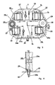
- Fig. 4 shows a section through a double actuator, as indicated above.
- a laminated anchor 25 is shown. This is connected to a shown anchor tube 21, in which a torsion bar 22 extends. It is also shown the bearing 23 and 23 a of the anchor tube in the bearing plate. This bearing 23 and 23a can be realized by sliding or rolling bearings.
- On the left side of the torsion bar 22 is connected to the anchor tube 21 and on the right side with a housing-fixed pivot rod receptacle 24, which is in turn connected to a lever 24a as an extension acting approximately in the center of the bearing plate 25 r with this at S 1 is welded.
- This welding allows accurate adjustment of the torsion bar force by the armature is brought into the closed position of the valve shown in Fig. 2 and then the torsion bar lever 24a is rotated until the corresponding force is reached. Subsequently, the welding takes place.
- a hydraulic clearance compensation element directly to the armature 25 and the required pressure oil, z. B. via a valve actuating lamella 25a of the armature 25 between the armature and valve arranged clearance compensation element (not shown) to supply.
- an oil connection 26 is necessary, which is preferably connected to a pressure line of a pump of the engine lubricating oil pump. So that the pressure oil does not escape from the bearing 23a, a sealing element 26a is arranged behind this bearing.
- the pressure oil passes via the anchor tube 21 into the channel 27 in the valve actuating lamella 25a.
- the valve actuating blade 25a is arranged off-center.
- the corresponding blade of the adjacent actuator (half of the picture) is designated 25a '.
- the distance of the fins 25a and 25a ' corresponds to the valve spacing. From this, the advantage of this arrangement can be seen, since it can be adapted to the valve distances in a wide range.
- the valve operating blades 25 a and 25 a ' are embedded in the armature packet.
- the bearing bushes 28 are welded or soldered. For exact alignment, this is done in a corresponding device.
- angle pieces of which in Fig. 6, the angle piece for the bearing plate 25 L is shown, the actuator with screws 29 is connected to the cylinder head 35.
- the bearing plates are relatively thin (about 1.5 to 2mm thick).
- the end lamellae are about 3mm thick, the other lamellae about 0.3mm.
- Fig. 4 shows the corresponding elements of the adjacent actuator.
- the outer yoke reinforcement is effected by the side plate 32, which is welded to the bearing plate at S 3 .
- For internal yoke reinforcement serves the side plate 33.
- the inner reinforcement protrudes namely the yoke side plate 33 through the bearing plate 25 L and is welded at S 2 with this.
- Fig. 5 shows a side view of the bearing plate 25 L.
- Fig. 4 shows the view in the drawn y-direction.
- the yoke side plates 32 and 33 are shown in dashed lines and compared to Fig. 1 and 2 dimensioned slightly different and also the implementation of the side plate 33 through a recess in the bearing plate 25 L with the corresponding welds S 2 can be seen.
- the torsion bar receptacle 24 and the lever 24a can be seen here.
- the parts 24 and 24a corresponding elements of the left adjacent actuator are arranged on the bearing plate 25 r diagonally opposite. Thus, the same parts can be used.
- the fastening screw 29 can be seen.
- connection cable By corresponding recesses of the bearing plates 25 L and 25 r projecting the coil 34 therethrough. Their connections 34a are thus easily accessible for contacting the connection cable.
- the Jochlamellenver can also be screwed with any additional welding or gluing or other connection options.
- the screw connections 37 and 37a shown on the left in FIG. 5 bring the advantage of a simple adjustment. It can, for. B. also only the upper magnet are screwed and the lower welded.
- the bearing plates 25L 1 and 25R have to be at least slightly magnetic in the region of the armature in order to produce only a small shunt.
- the material can be magnetic.
- the non-magnetic material, for. B. V2A costs a multiple of the magnetically conductive material. Therefore, it is conceivable to perform a separation at 25 LT , such that the middle part 25 LM is non-magnetic and the adjacent part above 25 LO and correspondingly below magnetic.
- the actuator In order to produce good heat dissipation, the actuator should be mounted flush with the bearing plates 25 L and 25 r .
- Fig. 5 and Fig. 6 show the attachment of the actuator by means of the fastening screw 29 on the cylinder head 35th
- a Shaft screw 29a can be used with a hexagon at the upper end. This design has mounting advantages the accessibility when placing on the cylinder head.
Landscapes
- Engineering & Computer Science (AREA)
- Physics & Mathematics (AREA)
- Electromagnetism (AREA)
- Power Engineering (AREA)
- Mechanical Engineering (AREA)
- General Engineering & Computer Science (AREA)
- Valve Device For Special Equipments (AREA)
Description
- Fig. 1
- den Aufbau eines Aktuators für den Antrieb eines Ventils eines Verbrennungsmotors in Schnittdarstellung, bei dessen Elektromagneten die Erfindung eingesetzt ist;
- Fig. 2
- den teilweise gezeigten Aktuator in perspektivischer Darstellung;
- Fig. 3
- eine teilweise alternative Ausbildung.
- Fig. 4
- einen Aufblick auf die Anker zweier benachbarter Aktuatoren;
- Fig. 5
- eine der Lagerplatten;
- Fig. 6
- eine Detail der Fig. 4 und 5.
Der Elektromagnet 3 kann in äquivalenter Weise zusammengebaut werden.
Claims (29)
- Elektromagnet (2, 3) mit einem eine elektrische Wicklung (2b, 3b) aufweisenden Joch (2a, 3a) und einem den Polen des Jochs (2a, 3a) gegenüberliegenden Anker (7), wobei das Joch (2a, 3a) aus Lamellen (2a') zusammengesetzt ist und Mittel (8, 9, 10 ) zum Zusammenhalt des Lamellenpakets (2a) vorgesehen sind,
dadurch gekennzeichnet, dass
das Lamellenpaket (2a) zwischen Endplatten, insbesondere Lagerplatten (8) angeordnet ist, dass diese durch längs des Lamellenpakets (2a) verlaufende, biegesteife Seitenplatten, insbesondere Jochseitenplatten (9, 10) miteinander verbunden sind, und dass die Lagerung des Ankers (7) in den Lagerplatten (8) untergebracht ist. - Elektromagnet nach Anspruch 1, dadurch gekennzeichnet, dass die Lamellen (2a') Ausbuchtungen (2a'') aufweisen, die ein Einhängen der Lamellen (2a') zwischen die Jochseitenplatten (9, 10) ermöglichen.
- Elektromagnet nach einem der Ansprüche 1 bis 3, dadurch gekennzeichnet, dass Ausbuchtungen (2a'') in der Nähe des von den Polen des Jochs (2a) abgewandten Endes des Jochs (2a) vorgesehen sind.
- Elektromagnet nach einem der Ansprüche 1 bis 3, dadurch gekennzeichnet, dass die Verbindung durch kraft- oder formschlüssige Fügeverfahren (z. B. Schweißen, Löten, Kleben, Verstemmen oder Einpassen) hergestellt ist.
- Elektromagnet nach einem der Ansprüche 1 bis 4, dadurch gekennzeichnet, dass die Jochseitenplatten (8, 9) aus unmagnetischem Material sind.
- Elektromagnet nach einem der Ansprüche 1 bis 5, dadurch gekennzeichnet, dass die Jochseitenplatten (9, 10) gegenüber dem Lamellenpaket (2a) elektrisch isoliert (11) sind.
- Elektromagnet nach einem der Ansprüche 1 bis 6, dadurch gekennzeichnet, dass wenigstens eine Seitenplatte (10) ein Profil aufweist.
- Elektromagnet nach einem der Ansprüche 1 bis 7, dadurch gekennzeichnet, dass benachbarte Lamellen durch eine Verzahnung ( z. B. sogenannte Stanzpaketierung) miteinander verbunden sind.
- Elektromagnet nach einem der Ansprüche 1 bis 8, dadurch gekennzeichnet, dass die Lamellen (2a'), insbesondere in Polnähe wenigstens teilweise zusätzlich durch eine Verschweißung oder Verlötung (bei 13) miteinander verbunden sind.
- Elektromagnet nach einem der Ansprüche 4 bis 9, dadurch gekennzeichnet dass die Herstellung der Verbindung der Jochseitenplatten (9, 10) mit den Lagerplatten (8) unter Verspannen des Lamellenpakets (2a') erfolgt.
- Elektromagnet nach einem der Ansprüche 1 bis 10, gekennzeichnet durch seine Anwendung als Teil eines elektromagnetischen Aktuators (1), bei dem der Anker (7) durch Magnetkraft (2, 3) in Verbindung mit zwei entgegengesetzt gerichteten Federkräften (6) in zwei Endstellungen gebracht wird und bei dem die Ankerbewegungen in die beiden Endstellungen zum Antrieb eines Ventils eines Verbrennungsmotors genutzt wird (über Verlängerung 4b).
- Elektromagnet nach einem der vorherigen Ansprüche, dadurch gekennzeichnet, dass wenigstens das Verbinden eines Endes der Seitenplatten (9, 10) mit der entsprchenden Endplatte (8) unter Zusammenpressen des Lamellenpakets (2a') und der Endplatten (8) erfolgt.
- Elektromagnet nach einem der vorherigen Ansprüche, dadurch gekennzeichnet, dass in den Lagerplatten (8) die Lagerung des Hebels (4) und damit des Ankers (7) über dessen Lagerrohr (4a) untergebracht ist.
- Aktuator nach Anspruch 11 bis 13, dadurch gekennzeichnet, dass an den Lagerplatten (8) die Jochseitenplatten (9, 10) zweier Elektromagnete befestigt sind und dass diese Anordnung des Aktuators eine Montageeinheit darstellt.
- Aktuator nach Anspruch 14, dadurch gekennzeichnet, dass die Endlamellen (31) des Lamellenpakets (30) im Vergleich zu den andern Lamellen ( Faktor 5 bis 10) dicker ausgebildet sind und mit den Lagerplatten (25r, 25L) verbunden sind und dass die Lagerplatten (25L, 25r) selbst dazu relativ dünn (1, 5 bis 2mm) ausgebildet sind.
- Aktuator nach einem der Ansprüche 11 bis 15, dadurch gekennzeichnet, dass der Anker (7) in den Lagerplatten (8) schwenkbar gelagert ist und eine mit dem Anker verbundene Drehfeder (5) wenigstens einen Teil der Federkräfte liefert.
- Aktuator nach einem der Ansprüche 11 bis 16, dadurch gekennzeichnet, dass er zusammen mit einem weiteren Aktuator eine Einheit bildet, die für beide Aktuatoren gemeinsame Lagerplatten (25r, 25L) aufweist, wobei sich die Aktuatoren gegenüberliegen (Fig. 4, Fig. 5).
- Aktuatoranordnung nach Anspruch 17, dadurch gekennzeichnet, dass die sich gegenüberliegenden Aktuatoren außermittig am Anker angebrachte Betätigungselemente für die Ventile aufweisen und um 180° gegeneinander verdreht angeordnet sind (Fig. 4).
- Aktuatoranordnung nach Anspruch 17 oder 18, dadurch gekennzeichnet, dass die gemeinsamen Lagerplatten (25r, 25L) auf einem Zylinderkopf oder Aktuatorträger befestigt sind.
- Aktuatoranordnung nach einem der Ansprüche 17 bis 19, dadurch gekennzeichnet, dass bei der Justage das Lagerspiel dadurch eliminiert wird, dass die Lagerung (4a) vorzugsweise in Richtung zum Magneten (2 und 3) hingedrückt wird.
- Aktuatoranordnung nach einem der Ansprüche 18 bis 20, dadurch gekennzeichnet, dass die beiden Lagerplatten (25r, 25L) durch Schrauben (37, 37a) miteinander verbunden sind.
- Aktuatoranordnung nach Anspruch 21, dadurch gekennzeichnet, dass zusätzlich die Jochseitenplatten (32, 33) mit den Lagerplatten (25r, 25L) verbunden (z. B. verschweißt, verklebt, verlötet) sind.
- Aktuatoranordnung nach einem der Ansprüche 18 bis 22, dadurch gekennzeichnet, dass die Buchsen (23) zur Lagerung der Anker (25) kraft- und/oder formschlüssig in die Lagerplatten (25r, 25L) eingebracht sind.
- Aktuatoranordnung nach Anspruch 23, dadurch gekennzeichnet, dass die Lagerbuchsen (23) zumindest näherungsweise auf der Mittellinie der Lagerplatten (25r, 25L) angeordnet sind.
- Aktuatoranordnung nach einem der Ansprüche 18 bis 24, dadurch gekennzeichnet, dass zur Justage des Drehstabes der Anker in zumindest eine Endstellung (z. B. Aufliegen auf dem Magneten 2) gebracht wird, dass hierbei der Drehstab mittels eines Hebels (24a) auf einen bestimmten Wert vorgespannt wird und dass anschließend der Hebel (24a) festgelegt wird (verschweißt).
- Aktuatoranordnung nach einem der Ansprüche 18 bis 25, dadurch gekennzeichnet, dass die Endlamellen (31) zweier Lamellenpakete wenigstens teilweise durch eine Brücke miteinander verbunden sind.
- Aktuatoranordnung nach einem der Ansprüche 18 bis 26, dadurch gekennzeichnet, dass die Lagerplatten (25r, 25L) aus mehreren Teilplatten (25LO, 25LM) zusammengesetzt sind, dass eine der Teilplatten (25LM) aus weitgehend unmagnetischem Material besteht und dass diese Teilplatte (25LM) im Bereich der Anker (25) angeordnet ist.
- Aktuator nach einem der Ansprüche 18 bis 27, dadurch gekennzeichnet, dass die Lagerplatten (25r, 25L) mittels eines Winkelstücks mit einem Aktuatorträger oder dem Zylinderblock (35) verbunden, insbesondere verschraubt sind.
- Verfahren zur Herstellung einer Aktuatoranordnung, gemäß den Ansprüchen 18 bis 27, dadurch gekennzeichnet, dass der Anker (25) in die polnahe Endstellung gebracht wird,
dass das Lamellenpaket auf minimalen Luftspalt zum Anker (25) justiert wird,
dass dann das Lamellenpaket zusammengepreßt wird und dass anschließend die Verbindungen zwischen den Lagerplatten (25r, 25L) und den Seitenplatten (32, 39) vorzugsweise gleichzeitig auf beiden Seiten erzeugt werden.
Applications Claiming Priority (3)
| Application Number | Priority Date | Filing Date | Title |
|---|---|---|---|
| DE10002628 | 2000-01-22 | ||
| DE10002628A DE10002628A1 (de) | 2000-01-22 | 2000-01-22 | Elektromagnet |
| PCT/EP2001/000565 WO2001054146A1 (de) | 2000-01-22 | 2001-01-18 | Elektromagnet |
Publications (2)
| Publication Number | Publication Date |
|---|---|
| EP1163687A1 EP1163687A1 (de) | 2001-12-19 |
| EP1163687B1 true EP1163687B1 (de) | 2004-09-01 |
Family
ID=7628349
Family Applications (1)
| Application Number | Title | Priority Date | Filing Date |
|---|---|---|---|
| EP01942784A Expired - Lifetime EP1163687B1 (de) | 2000-01-22 | 2001-01-18 | Elektromagnet |
Country Status (3)
| Country | Link |
|---|---|
| EP (1) | EP1163687B1 (de) |
| DE (2) | DE10002628A1 (de) |
| WO (1) | WO2001054146A1 (de) |
Families Citing this family (5)
| Publication number | Priority date | Publication date | Assignee | Title |
|---|---|---|---|---|
| DE10134708A1 (de) * | 2001-07-21 | 2003-02-06 | Heinz Leiber | Elektromagnet |
| FR2834119B1 (fr) * | 2001-08-30 | 2004-05-21 | Moving Magnet Tech Mmt | Actionneur electromagnetique a deux positions stables de fin de course, notamment pour la commande de vannes de conduits d'admission d'air pour moteurs a combustion interne |
| DE10218471A1 (de) * | 2002-04-25 | 2003-11-06 | Mann & Hummel Filter | Magnetisch steuerbares Stellglied |
| DE10220788A1 (de) * | 2002-05-10 | 2003-11-20 | Daimler Chrysler Ag | Elektromagnetischer Aktuator mit einem Schwenkanker |
| EP2133538B1 (de) * | 2008-06-10 | 2012-12-12 | Arno Hofmann | Gasführendes Drehventil mit Torsionsfeder |
Family Cites Families (9)
| Publication number | Priority date | Publication date | Assignee | Title |
|---|---|---|---|---|
| DE1250552B (de) * | 1967-09-21 | |||
| DE946169C (de) * | 1942-06-19 | 1956-07-26 | Aeg | Geblaetterter Magnetkern |
| DE967478C (de) * | 1942-11-29 | 1957-11-14 | Westfaelische Metall Ind G M B | Vorrichtung zum Paketieren von lamellierten Elektromagneten fuer elektromagnetische Signalhoerner |
| JPS6313306A (ja) * | 1986-07-04 | 1988-01-20 | Hitachi Ltd | 電磁石鉄心,及びその製作方法 |
| WO1998042958A1 (de) * | 1997-03-24 | 1998-10-01 | Lsp Innovative Automotive Systems Gmbh | Elektromagnetische stellvorrichtung |
| US6049264A (en) * | 1997-12-09 | 2000-04-11 | Siemens Automotive Corporation | Electromagnetic actuator with composite core assembly |
| US6118366A (en) * | 1997-12-09 | 2000-09-12 | Siemens Automotive Corporation | Electromagnetic actuator with split housing assembly |
| DE19807181A1 (de) * | 1998-02-20 | 1999-08-26 | Bayerische Motoren Werke Ag | Elektromagnetische Schwinganker-Vorrichtung, insbesondere als Aktuator für ein Gaswechselventil einer Kraft- oder Arbeitsmaschine |
| DE19824537A1 (de) * | 1998-06-03 | 1999-12-09 | Lsp Innovative Automotive Sys | Elektromagnetische Stelleinrichtung |
-
2000
- 2000-01-22 DE DE10002628A patent/DE10002628A1/de not_active Withdrawn
-
2001
- 2001-01-18 DE DE50103445T patent/DE50103445D1/de not_active Expired - Fee Related
- 2001-01-18 EP EP01942784A patent/EP1163687B1/de not_active Expired - Lifetime
- 2001-01-18 WO PCT/EP2001/000565 patent/WO2001054146A1/de not_active Ceased
Also Published As
| Publication number | Publication date |
|---|---|
| DE50103445D1 (de) | 2004-10-07 |
| WO2001054146A1 (de) | 2001-07-26 |
| DE10002628A1 (de) | 2001-07-26 |
| EP1163687A1 (de) | 2001-12-19 |
Similar Documents
| Publication | Publication Date | Title |
|---|---|---|
| DE60117320T2 (de) | Elektromagnetischer Aktuator mit lamelliertem Anker zur Betätigung der Ventile einer Brennkraftmaschine | |
| EP0970295B1 (de) | Elektromagnetischer antrieb | |
| DE10339214B4 (de) | Magnetischer Betätiger | |
| DE69825713T2 (de) | Elektromagnetischer Betätiger mit Verbundkernanordnung | |
| EP3494632B1 (de) | Motorkomponente, primärteil und linearmotor | |
| EP3018392B1 (de) | Elektromagnetischer Ventilantrieb, Verfahren zu seiner Herstellung und damit ausgestattetes Magnetventil | |
| DE19955079A1 (de) | Elektromagnetischer Antrieb | |
| DE19955054A1 (de) | Elektromagnetischer Antrieb | |
| DE10053465A1 (de) | Kern eines Solenoid-Aktuators | |
| EP1163687A1 (de) | Elektromagnet | |
| WO1999020434A1 (de) | Magnetische spannvorrichtung für miteinander zu verschweissende zuschnitte aus ferromagnetischem stahlblech | |
| DE19959021B4 (de) | Elektromagnetisch betätigbares Proportionalventil | |
| EP1059646A1 (de) | Aktor zur elektromagnetischen Ventilsteuerung | |
| DE19955067A1 (de) | Elektromagnetischer Aktuator | |
| DE3928066A1 (de) | Vorrichtung zur elektromagnetischen steuerung eines gaswechsel-ventils einer hubkolben-brennkraftmaschine | |
| EP1163686B1 (de) | Elektromagnet | |
| DE3533817C2 (de) | ||
| DE102014213276A1 (de) | Linearantrieb mit hoher Kraftdichte | |
| DE112013002312B4 (de) | Gravierorgan zur Gravur von Druckformen | |
| DE19948207A1 (de) | Elektromagnetischer Aktuator | |
| DE10002295A1 (de) | Elektromagnet | |
| DE102004062340A1 (de) | Elektromagnetischer Antrieb mit Flußleitstücken | |
| DE10039869A1 (de) | Elektromagnet | |
| DE3018972C2 (de) | Magnetventil | |
| WO2000046490A1 (de) | Elektromagnetischer aktuator mit geblechtem anker |
Legal Events
| Date | Code | Title | Description |
|---|---|---|---|
| PUAI | Public reference made under article 153(3) epc to a published international application that has entered the european phase |
Free format text: ORIGINAL CODE: 0009012 |
|
| AK | Designated contracting states |
Kind code of ref document: A1 Designated state(s): AT BE CH CY DE DK ES FI FR GB GR IE IT LI LU MC NL PT SE TR |
|
| 17P | Request for examination filed |
Effective date: 20020103 |
|
| GRAP | Despatch of communication of intention to grant a patent |
Free format text: ORIGINAL CODE: EPIDOSNIGR1 |
|
| GRAS | Grant fee paid |
Free format text: ORIGINAL CODE: EPIDOSNIGR3 |
|
| GRAA | (expected) grant |
Free format text: ORIGINAL CODE: 0009210 |
|
| AK | Designated contracting states |
Kind code of ref document: B1 Designated state(s): DE FR |
|
| REG | Reference to a national code |
Ref country code: IE Ref legal event code: FG4D Free format text: GERMAN |
|
| REF | Corresponds to: |
Ref document number: 50103445 Country of ref document: DE Date of ref document: 20041007 Kind code of ref document: P |
|
| PGFP | Annual fee paid to national office [announced via postgrant information from national office to epo] |
Ref country code: DE Payment date: 20050202 Year of fee payment: 5 |
|
| PGFP | Annual fee paid to national office [announced via postgrant information from national office to epo] |
Ref country code: FR Payment date: 20050216 Year of fee payment: 5 |
|
| REG | Reference to a national code |
Ref country code: IE Ref legal event code: FD4D |
|
| PLBE | No opposition filed within time limit |
Free format text: ORIGINAL CODE: 0009261 |
|
| STAA | Information on the status of an ep patent application or granted ep patent |
Free format text: STATUS: NO OPPOSITION FILED WITHIN TIME LIMIT |
|
| ET | Fr: translation filed | ||
| 26N | No opposition filed |
Effective date: 20050602 |
|
| PG25 | Lapsed in a contracting state [announced via postgrant information from national office to epo] |
Ref country code: FR Free format text: LAPSE BECAUSE OF NON-PAYMENT OF DUE FEES Effective date: 20060131 |
|
| PG25 | Lapsed in a contracting state [announced via postgrant information from national office to epo] |
Ref country code: DE Free format text: LAPSE BECAUSE OF NON-PAYMENT OF DUE FEES Effective date: 20060801 |
|
| REG | Reference to a national code |
Ref country code: FR Ref legal event code: ST Effective date: 20060929 |