EP1163686B1 - Elektromagnet - Google Patents
Elektromagnet Download PDFInfo
- Publication number
- EP1163686B1 EP1163686B1 EP01909656A EP01909656A EP1163686B1 EP 1163686 B1 EP1163686 B1 EP 1163686B1 EP 01909656 A EP01909656 A EP 01909656A EP 01909656 A EP01909656 A EP 01909656A EP 1163686 B1 EP1163686 B1 EP 1163686B1
- Authority
- EP
- European Patent Office
- Prior art keywords
- actuator
- side plates
- yoke side
- yoke
- lamellae
- Prior art date
- Legal status (The legal status is an assumption and is not a legal conclusion. Google has not performed a legal analysis and makes no representation as to the accuracy of the status listed.)
- Expired - Lifetime
Links
- 241000446313 Lamella Species 0.000 claims description 9
- 238000003466 welding Methods 0.000 claims description 8
- 238000009413 insulation Methods 0.000 claims description 4
- 238000002485 combustion reaction Methods 0.000 claims description 3
- 239000004033 plastic Substances 0.000 claims description 3
- 238000005266 casting Methods 0.000 claims description 2
- 239000003973 paint Substances 0.000 claims description 2
- 238000005476 soldering Methods 0.000 claims description 2
- 239000004020 conductor Substances 0.000 claims 1
- 238000007765 extrusion coating Methods 0.000 claims 1
- 239000011888 foil Substances 0.000 claims 1
- 239000012528 membrane Substances 0.000 claims 1
- 239000012811 non-conductive material Substances 0.000 claims 1
- 238000007789 sealing Methods 0.000 claims 1
- 238000004873 anchoring Methods 0.000 description 4
- 238000005452 bending Methods 0.000 description 3
- 230000008901 benefit Effects 0.000 description 3
- 238000004804 winding Methods 0.000 description 3
- 229910052782 aluminium Inorganic materials 0.000 description 2
- XAGFODPZIPBFFR-UHFFFAOYSA-N aluminium Chemical compound [Al] XAGFODPZIPBFFR-UHFFFAOYSA-N 0.000 description 2
- 239000002131 composite material Substances 0.000 description 2
- 238000010276 construction Methods 0.000 description 2
- 238000003860 storage Methods 0.000 description 2
- 230000001419 dependent effect Effects 0.000 description 1
- 238000004512 die casting Methods 0.000 description 1
- 230000000694 effects Effects 0.000 description 1
- 238000005538 encapsulation Methods 0.000 description 1
- 230000002349 favourable effect Effects 0.000 description 1
- 238000002955 isolation Methods 0.000 description 1
- 239000000696 magnetic material Substances 0.000 description 1
- 238000004519 manufacturing process Methods 0.000 description 1
- 229910052751 metal Inorganic materials 0.000 description 1
- 239000002184 metal Substances 0.000 description 1
- 238000000034 method Methods 0.000 description 1
- 239000002245 particle Substances 0.000 description 1
- 239000002985 plastic film Substances 0.000 description 1
- 229920006255 plastic film Polymers 0.000 description 1
- 239000011347 resin Substances 0.000 description 1
- 229920005989 resin Polymers 0.000 description 1
Images



Classifications
-
- H—ELECTRICITY
- H01—ELECTRIC ELEMENTS
- H01F—MAGNETS; INDUCTANCES; TRANSFORMERS; SELECTION OF MATERIALS FOR THEIR MAGNETIC PROPERTIES
- H01F3/00—Cores, Yokes, or armatures
- H01F3/02—Cores, Yokes, or armatures made from sheets
-
- F—MECHANICAL ENGINEERING; LIGHTING; HEATING; WEAPONS; BLASTING
- F01—MACHINES OR ENGINES IN GENERAL; ENGINE PLANTS IN GENERAL; STEAM ENGINES
- F01L—CYCLICALLY OPERATING VALVES FOR MACHINES OR ENGINES
- F01L9/00—Valve-gear or valve arrangements actuated non-mechanically
- F01L9/20—Valve-gear or valve arrangements actuated non-mechanically by electric means
-
- H—ELECTRICITY
- H01—ELECTRIC ELEMENTS
- H01F—MAGNETS; INDUCTANCES; TRANSFORMERS; SELECTION OF MATERIALS FOR THEIR MAGNETIC PROPERTIES
- H01F7/00—Magnets
- H01F7/06—Electromagnets; Actuators including electromagnets
- H01F7/08—Electromagnets; Actuators including electromagnets with armatures
- H01F7/081—Magnetic constructions
-
- H—ELECTRICITY
- H01—ELECTRIC ELEMENTS
- H01F—MAGNETS; INDUCTANCES; TRANSFORMERS; SELECTION OF MATERIALS FOR THEIR MAGNETIC PROPERTIES
- H01F7/00—Magnets
- H01F7/06—Electromagnets; Actuators including electromagnets
- H01F7/08—Electromagnets; Actuators including electromagnets with armatures
- H01F7/14—Pivoting armatures
-
- F—MECHANICAL ENGINEERING; LIGHTING; HEATING; WEAPONS; BLASTING
- F01—MACHINES OR ENGINES IN GENERAL; ENGINE PLANTS IN GENERAL; STEAM ENGINES
- F01L—CYCLICALLY OPERATING VALVES FOR MACHINES OR ENGINES
- F01L9/00—Valve-gear or valve arrangements actuated non-mechanically
- F01L9/20—Valve-gear or valve arrangements actuated non-mechanically by electric means
- F01L9/21—Valve-gear or valve arrangements actuated non-mechanically by electric means actuated by solenoids
- F01L2009/2105—Valve-gear or valve arrangements actuated non-mechanically by electric means actuated by solenoids comprising two or more coils
- F01L2009/2109—The armature being articulated perpendicularly to the coils axes
Definitions
- the invention relates to electromagnets with the features of the preamble of claim 1.
- Joches of magnetic circuits for electromagnets are bolted or obtained by beading in the sheets together a positive connection, by so-called stamped packetization. This is the usual technique, eg. B. for ignition transformers. Most of these yokes are also molded with plastic. This encapsulation serves the cohesion of the disk pack and to its isolation. Problematic the residual stress of thin sheets that resemble disc springs act and a dense composite in which each sheet without Game is in the composite, by bracing with Making screws very difficult.
- the invention is based on the object, the yoke training to make a solenoid stiffer, to avoid the above-mentioned disadvantages.
- Fig. 1 and Fig. 2 is an electromagnetic actuator 1 for a valve actuation of an internal combustion engine.
- the actuator 1 has two electromagnets 2 and 3 consisting of two-pole yokes 2a and 3a and one each Winding 2b and 3b.
- the electromagnets 2 and 3 work with a lever 4 together, with an anchor tube 4a is connected.
- This anchor tube 4a is about an axis. 5 pivoted.
- a Torsion spring 6 is arranged in the form of a rotary tube, the is rigidly clamped at one end and with his other End is connected to the anchor tube 4a.
- the torsion bar 6 generated in this embodiment, the on the lever 4 acting two spring forces.
- the lever 4 carries a Anchor 7, which cooperates with the electromagnets 2 and 3 and generates the pivoting movement.
- the right end 4b of the lever 4 acts on a shaft, not shown of the valve.
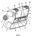
- Fig. 2 shows that the yoke 2a of fins 2a 'and 2a' 'composed of magnetic material is.
- the end plates 2a '' the yokes 2a and 3a are made thicker (e.g., 3mm) and as also shown in Figs. 3a and 3b (section X - X), also welded to the yoke side plates 8.
- Fig. 3a and Fig. 3b is in each case one of the welded joints 8 'between the Jochendlamellen 2a' 'and the Yoke side plates 8 shown. This creates between the two yoke side plates and the end plates a cage, where the yoke side plates are fully on the Endlamellen rigidly support the large magnetic forces to catch the slats.
- a Weld 8 '' between the yoke side plate 8 and the bearing plate 12 shown in a recess 8 '' ' is appropriate.
- the bearing plate 12 directly with the yoke side plate 8 connected.
- the Weld 8 '' also by a through-welding 12 '' replaced by the bearing plate 12 to the end plate 2a '' his. Both can also be used simultaneously.
- the disk set before welding strongly compressed so that the lamellae close together lie. This can be done with a bracing device be effected, which will be described later.
- Fig. 4 shows again the structure of the electromagnet of Fig. 1 with the laminated yoke 2a, with the thin Slats 2a 'and the thicker end plates 2a ", the winding 2b and the bearing plate 12.
- the left side plate 8a at its upper end 8a ' is bent and is arranged outside the winding 2b.
- a high bending stiffness is achieved. It is welded at least at the top with the slats.
- the thick end plates used 2a "set a stiffening of the package; thin platelets would bulge because of the spring action of the disk pack and can not transfer the ones transferred to the yoke side plate absorb high magnetic forces.
- the yoke side plates 8 and 8a with manufactured with a small length tolerance (eg ⁇ 20 [m]. This makes it possible the plate pack 2a without editing the end faces of the end plates 2a '' together and to weld to the bearing plate, wherein the weld preferably over a large length of the contact surface is made.
- Fig. 6 shows a case where the yoke side plates 8 and 8a are butt welded to the bearing plate 12 (Welds 12 '' '). In addition, there may be a weld 12 '' between the thick end plate 2a '' and the bearing plate 12 done.
- Fig. 7 the front view of a combination of two Actuators 40 and 41 shown behind a common Bearing plate 42 are located.
- the actuator 41 corresponds the position of the actuator 1 in Fig. 1.
- the actuator 40 is opposite the actuator 41; he is against it is rotated by 180 °, so that in Fig. 7, left at 41a the storage of the anchor tube and its connection to the Rotary tube 41b corresponding to the illustration of FIG. 2 is located and right at 40a the clamping of the rotary tube 40b in the bearing plate 42.
- the rear and front bearing plate 42 are mounted on an actuator carrier 43.
- the Valve actuations 44 corresponding to 4b, are correspondingly spatially offset the valve spacing in the cylinder head.
- FIG. 7 now shows possible welds 45 and 46 between the common bearing plate 42 and the behind lying end lamellae of the four yokes.
- the weld 47 would mapped according to the U-shape of the magnet, such as this is shown in the upper part of the actuator 41.
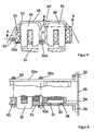
- Fig. 8 shows an embodiment in which the yoke side plates to an embedding of the disk pack in one Sheath 48 are expanded by pouring or overmolding be made with metal or plastic can.
- metal or plastic can Preferably here aluminum die casting offers on.
- the case 48 On the left half of the picture is the case 48 with the disk pack 49 shown.
- the coil 50 In the yoke, the coil 50 is mounted. At the end of the yoke legs, a part of the armature 51 is shown.
- This shell 48 is here by means of screws 52 and 52a is clamped between the bearing plates 53 and 53a (see Fig. 9). The clamping forces of the screws act predominantly only on the case 48. For better adhesion of the disk pack 49 on the shell 48 has the disk pack cam 49 'for anchoring.
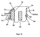
- through-bolts 64 on the yoke side plates 61 and 62 are here designed as sheet bending parts on the left with inversion around the screw 64 and partly with welded together (weld S M ). These are welded at the welds S 1 to S 4 with the disk set.
- the screws have advantages in terms of fine adjustment of the magnetic yoke to the anchor. In addition, they reduce the deflection of the yokes and thus support the yoke side plates 61 and 62.
- the yoke side plate 61 and 62 are welded to the bearing plates 53, and 53a, respectively.
- the coil with bobbin 50a is shown.
- the yoke leg may have a toothing.
- the yoke leg may have a toothing.
- the z. B. Shrunk is, so that no air gap arises.
Landscapes
- Engineering & Computer Science (AREA)
- Physics & Mathematics (AREA)
- Electromagnetism (AREA)
- Power Engineering (AREA)
- Mechanical Engineering (AREA)
- General Engineering & Computer Science (AREA)
- Electromagnets (AREA)
Description
- Fig. 1
- den Aufbau eines Aktuators für den Antrieb eines Ventils eines Verbrennungsmotors, bei dessen Elektromagneten die Erfindung eingesetzt ist;
- Fig. 2
- den Aktuator in perspektivischer Darstellung;
- Fig. 3a und 3b
- alternative Details der Verschweißung;
- Fig. 4 bis 6
- weitere Details des Jochaufbaus;
- Fig. 7
- den Zusammenbau zweier benachbarter Aktuatoren;
- Fig. 8 bis 10
- weitere Möglichkeiten der Ausgestaltung.
Claims (32)
- Elektromagnet (2, 3) mit einem eine elektrische Wicklung (2b, 3b) aufweisenden Joch (2a, 3a) und einem den Polen des Jochs (2a, 3a) gegenüberliegenden Anker (7), wobei das Joch (2a, 3a) aus Lamellen (2a', 2a'') zusammengesetzt ist und Mittel (8, 9, 10) zum Zusammenhalt des Lamellenpakets vorgesehen sind, dadurch gekennzeichnet, daß wenigstens an einem Teil der Seitenflächen vorzugsweise an den äußeren Seitenflächen des Lamellenpakets (2a, 3a) über dessen Tiefe Jochseitenplatten (8, 9) angeordnet sind und daß die Lamellen (2a', 2a'') wenigstens teilweise mit den Jochseitenplatten (8, 9) verschweißt, verlötet, verklebt oder formschlüssig verbunden sind.
- Elektromagnet nach Anspruch 1, dadurch gekennzeichnet, daß das Lamellenpaket vor und während dem Verschweißen oder Verlöten usw. zusammengepreßt wird.
- Elektromagnet nach Anspruch 1 oder 2, dadurch gekennzeichnet, daß die Ränder der Jochseitenplatten (8, 9) an ihren Auflagestellen (10) mit wenigstens einem Teil der Lamellen (2a') verschweißt, verlötet oder verklebt sind.
- Elektromagnet nach einem der Ansprüche 1 - 3, dadurch gekennzeichnet, daß die Jochseitenplatten (8, 9) in enger Passung formschlüssig in die Lamellen (2a', 2a") eingepreßt sind.
- Elektromagnet nach einem der Ansprüche 1 bis 4, dadurch gekennzeichnet, daß die Endlamellen (2a'') dicker als die übrigen Lamellen (2a') ausgebildet sind und daß diese Endlamellen (2a'') mit den Jochseitenplatten (8, 9) verschweißt oder verlötet usw. sind.
- Elektromagnet nach einem der Ansprüche 1 bis 5 dadurch gekennzeichnet, daß die Jochseitenplatten (8, 9) aus magnetisch nicht leitendem Material bestehen.
- Elektromagnet nach einem der Ansprüche 1 bis 5, dadurch gekennzeichnet, daß die Jochseitenplatten (8, 9) aus magnetisch leitendem Material bestehen
- Elektromagnet nach einem der Ansprüche 1 bis 7, dadurch gekennzeichnet, daß eine Laserschweißung angewendet wird.
- Elektromagnet nach einem der Ansprüche 1 bis 8, dadurch gekennzeichnet, daß die Jochseitenplatten (8, 8a) zur Verringerung von Wirbelströmen außerhalb der Wicklungen (2b, 3b) angebracht sind.
- Elektromagnet nach Anspruch 9, dadurch gekennzeichnet, daß die eine Jochseitenplatte (8a) in ihrem oberen Teil (8a') zur Umfassung der Wicklung (2b) abgekröpft ist.
- Elektromagnet nach einem der Ansprüche 1 bis 10, dadurch gekennzeichnet, daß eine Isolierung (15) zwischen den dünnen Lamellen (2a') und den Jochseitenplatten (8, 9) vorgesehen ist.
- Elektromagnet nach einem der Ansprüche 1 bis 11, dadurch gekennzeichnet, daß die Jochseitenplatten (8, 9) etwa parallel zu den Lamellen (2a) mit wenigstens einem Schlitz (13) versehen sind.
- Elektromagnet nach einem der Ansprüche 1 bis 12, dadurch gekennzeichnet, dass die Jochseitenplatten (61, 62) mittels Durchgangsschrauben (60) mit den Lagerplatten (53, 53a) verbunden sind.
- Elektromagnet nach einem der Ansprüche 1 bis 13, dadurch gekennzeichnet, dass eine mechanische Abdichtung (Dichtungsschale 63) des Luftspalts zwischen dem Anker den Polen gegenüber der Wicklung vorgesehen ist.
- Elektromagnet nach einem der Ansprüche 1 bis 14, gekennzeichnet durch seine Anwendung als Teil eines elektromagnetischen Aktuators (1), bei dem der Anker (7) durch Magnetkraft (2, 3) in Verbindung mit zwei entgegengesetzt gerichteten Federkräften (6) in zwei Endstellungen gebracht wird und bei dem die Ankerbewegungen in die beiden Endstellungen zum Antrieb eines Ventils eines Verbrennungsmotors genutzt wird (über Verlängerung 4b).
- Aktuator nach Anspruch 15, dadurch gekennzeichnet, daß bei Verwendung von Lagerplatten (12) an denen der Aktuator (1) befestigt und gehalten ist, auch diese Lagerplatten (12) direkt (Fig. 3a und Fig. 6) oder indirekt (Fig. 3b) mit den Jochseitenplatten (8) verschweißt oder verlötet usw. sind.
- Aktuator nach Anspruch 15, dadurch gekennzeichnet daß zwischen den Lagerplatten (12) und dem Lamellenpaket eine Isolierung insbesondere eine Kunststofffolie oder eine Lackierung eingebracht ist.
- Aktuator nach Anspruch 15, 16 oder 17, dadurch gekennzeichnet, daß der Anker (7) schwenkbar gelagert ist und eine mit dem Anker verbundene Drehfeder (5) wenigstens einen Teil der Federkräfte liefert.
- Aktuator nach einem der Ansprüche 15 bis 18, dadurch gekennzeichnet, daß dessen Endlamellen und/oder Jochseitenplatten zusammen mit den Endlamellen und/oder Jochseitenplatten eines weiteren Aktuators (40) mit für beide Aktuatoren (40, 41) gemeinsamen Lagerplatten (42) verschweißt usw. sind, wobei sich die Aktuatoren (40, 41) gegenüberliegen.
- Aktuator nach einem der Ansprüche 15 bis 19, dadurch gekennzeichnet, daß die Jochseitenplatten (8, 9) in ihrer Länge eng toleriert sind.
- Aktuator nach Anspruch 20, dadurch gekennzeichnet, daß die Jochseitenplatten (8, 9) vorzugsweise über einen großen Teil der Länge direkt mit den Lagerplatten (12) verschweißt usw. sind.
- Aktuator nach einem der Ansprüche 20 oder 21, dadurch gekennzeichnet, daß die Lamellenpakete (2a, 3a) über die Seitenplatten (8, 9) mittels einer Spannvorrichtung auf konstante Länge verspannt und dann verschweißt usw. werden.
- Aktuator nach einem der Ansprüche 15 bis 22, dadurch gekennzeichnet, daß zur Justage der Magnete der Anker in den Endstellungen jeweils fixiert wird, daß die Joche jeweils auf den Anker gepreßt werden (vorzugsweise durch die eigene Magnetkraft) und daß danach die Verschweißung zwischen Jochendlamelle und Lagerplatte erfolgt.
- Aktuator nach Anspruch 23, dadurch gekennzeichnet, daß bei der Justage das Lagerspiel dadurch eliminiert wird, daß das Lagerrohr (4a) vorzugsweise in Richtung zum Magneten (2) hin gedrückt wird.
- Aktuatoranordnung nach Anspruch 19, dadurch gekennzeichnet, daß die sich gegenüberliegenden Aktuatoren um 180° gegeneinander verdreht angeordnet sind.
- Aktuatoranordnung nach Anspruch 19 oder 25, dadurch gekennzeichnet, daß die gemeinsamen Lagerplatten (42) auf einem Aktuatorträger oder Zylinderkopf (43) befestigt sind.
- Aktuatoranordnung nach einem der Ansprüche 1 bis 26, dadurch gekennzeichnet, daß eine Jochseitenplatte (8, 9) mit den Lagerplatten (12) zuerst nur teilweise verschweißt wird, dann zur anderen Jochseitenplatte (8, 9) gewechselt wird, wobei die Verschweißungen vorzugsweise diagonal vorgenommen werden.
- Aktuatoranordnung nach einem der Ansprüche 15 bis 27, dadurch gekennzeichnet, dass die Jochseitenplatten zu einer das Lamellenpaket (49) seitlich wenigstens weitgehend umgebenden Hülle (48, 54) aufgeweitet sind.
- Aktuatoranordnung nach Anspruch 28, dadurch gekennzeichnet, dass die Hülle (48, 54) durch Umspritzen oder Umgießen erzeugt wird.
- Aktuatoranordnung nach Anspruch 28 oder 29, dadurch gekennzeichnet, dass die Hülle (48, 54) mittels Durchgangsschrauben (52, 52a) mit dem Lagerplatten (53, 53a) verbunden ist.
- Aktuatoranordnung nach einem der Ansprüche 28 bis 30, dadurch gekennzeichnet, dass das Lamellenpaket an der der Hülle (48, 54) zugewandten Fläche Nocken (49a) und/oder Aussparungen aufweist.
- Aktuatoranordnung nach einem der Ansprüche 28 bis 31, dadurch gekennzeichnet, dass die Hülle (48, 54) mit den Endlamellen (55) und diese mit den Lagerplatten verbunden, insbesondere verschweißt sind.
Applications Claiming Priority (5)
| Application Number | Priority Date | Filing Date | Title |
|---|---|---|---|
| DE10002295 | 2000-01-20 | ||
| DE10002295A DE10002295A1 (de) | 2000-01-20 | 2000-01-20 | Elektromagnet |
| DE10039869 | 2000-08-16 | ||
| DE10039869A DE10039869A1 (de) | 2000-08-16 | 2000-08-16 | Elektromagnet |
| PCT/EP2001/000569 WO2001054147A1 (de) | 2000-01-20 | 2001-01-18 | Elektromagnet |
Publications (2)
| Publication Number | Publication Date |
|---|---|
| EP1163686A1 EP1163686A1 (de) | 2001-12-19 |
| EP1163686B1 true EP1163686B1 (de) | 2004-07-28 |
Family
ID=26003940
Family Applications (1)
| Application Number | Title | Priority Date | Filing Date |
|---|---|---|---|
| EP01909656A Expired - Lifetime EP1163686B1 (de) | 2000-01-20 | 2001-01-18 | Elektromagnet |
Country Status (3)
| Country | Link |
|---|---|
| EP (1) | EP1163686B1 (de) |
| DE (1) | DE50102969D1 (de) |
| WO (1) | WO2001054147A1 (de) |
Families Citing this family (2)
| Publication number | Priority date | Publication date | Assignee | Title |
|---|---|---|---|---|
| JP2008202427A (ja) * | 2007-02-16 | 2008-09-04 | Toyota Motor Corp | 電磁駆動弁 |
| EP3133615B1 (de) * | 2015-08-20 | 2018-12-26 | Siemens Aktiengesellschaft | Elektrische wicklungsanordnung |
Family Cites Families (4)
| Publication number | Priority date | Publication date | Assignee | Title |
|---|---|---|---|---|
| DE946169C (de) * | 1942-06-19 | 1956-07-26 | Aeg | Geblaetterter Magnetkern |
| JPS6313306A (ja) * | 1986-07-04 | 1988-01-20 | Hitachi Ltd | 電磁石鉄心,及びその製作方法 |
| WO1998042958A1 (de) * | 1997-03-24 | 1998-10-01 | Lsp Innovative Automotive Systems Gmbh | Elektromagnetische stellvorrichtung |
| DE19824537A1 (de) * | 1998-06-03 | 1999-12-09 | Lsp Innovative Automotive Sys | Elektromagnetische Stelleinrichtung |
-
2001
- 2001-01-18 DE DE50102969T patent/DE50102969D1/de not_active Expired - Lifetime
- 2001-01-18 WO PCT/EP2001/000569 patent/WO2001054147A1/de not_active Ceased
- 2001-01-18 EP EP01909656A patent/EP1163686B1/de not_active Expired - Lifetime
Also Published As
| Publication number | Publication date |
|---|---|
| DE50102969D1 (de) | 2004-09-02 |
| WO2001054147A1 (de) | 2001-07-26 |
| EP1163686A1 (de) | 2001-12-19 |
Similar Documents
| Publication | Publication Date | Title |
|---|---|---|
| DE29712502U1 (de) | Elektromagnetischer Aktuator mit Gehäuse | |
| DE60117320T2 (de) | Elektromagnetischer Aktuator mit lamelliertem Anker zur Betätigung der Ventile einer Brennkraftmaschine | |
| EP1430490B1 (de) | Elektromagnetischer aktuator | |
| EP3018392B1 (de) | Elektromagnetischer Ventilantrieb, Verfahren zu seiner Herstellung und damit ausgestattetes Magnetventil | |
| EP0970295A1 (de) | Elektromagnetischer antrieb | |
| EP1723713B1 (de) | Lineare antriebseinrichtung mit einem einen magnetträger aufweisenden ankerkörper | |
| DE10053465A1 (de) | Kern eines Solenoid-Aktuators | |
| DE102017131246B4 (de) | Ventil mit elektrodynamischen Aktor | |
| DE10053464A1 (de) | Kern eines Solenoid-Aktuators | |
| EP0935054A2 (de) | Elektromagnetischer Aktuator | |
| EP1163687B1 (de) | Elektromagnet | |
| WO2001054147A1 (de) | Elektromagnet | |
| DE3928066A1 (de) | Vorrichtung zur elektromagnetischen steuerung eines gaswechsel-ventils einer hubkolben-brennkraftmaschine | |
| DE19955067A1 (de) | Elektromagnetischer Aktuator | |
| DE10039869A1 (de) | Elektromagnet | |
| DE19948207A1 (de) | Elektromagnetischer Aktuator | |
| EP1869756B1 (de) | Linearaktor | |
| DE10002295A1 (de) | Elektromagnet | |
| DE19922426C2 (de) | Elektromechanischer Stellantrieb | |
| DE19920094A1 (de) | Elektromagnet mit einem Blechpaket | |
| DE19928622A1 (de) | Längsgeblechter Jochkörper für einen Elektromagneten | |
| WO1998042958A1 (de) | Elektromagnetische stellvorrichtung | |
| DE3018972C2 (de) | Magnetventil | |
| WO2000046490A1 (de) | Elektromagnetischer aktuator mit geblechtem anker | |
| DE69508096T2 (de) | Mehrphasigen dynamoelektrischen Schwingungserreger |
Legal Events
| Date | Code | Title | Description |
|---|---|---|---|
| PUAI | Public reference made under article 153(3) epc to a published international application that has entered the european phase |
Free format text: ORIGINAL CODE: 0009012 |
|
| AK | Designated contracting states |
Kind code of ref document: A1 Designated state(s): AT BE CH CY DE DK ES FI FR GB GR IE IT LI LU MC NL PT SE TR |
|
| 17P | Request for examination filed |
Effective date: 20020103 |
|
| GRAP | Despatch of communication of intention to grant a patent |
Free format text: ORIGINAL CODE: EPIDOSNIGR1 |
|
| GRAS | Grant fee paid |
Free format text: ORIGINAL CODE: EPIDOSNIGR3 |
|
| GRAA | (expected) grant |
Free format text: ORIGINAL CODE: 0009210 |
|
| AK | Designated contracting states |
Kind code of ref document: B1 Designated state(s): DE FR |
|
| REG | Reference to a national code |
Ref country code: IE Ref legal event code: FG4D Free format text: GERMAN |
|
| REF | Corresponds to: |
Ref document number: 50102969 Country of ref document: DE Date of ref document: 20040902 Kind code of ref document: P |
|
| REG | Reference to a national code |
Ref country code: IE Ref legal event code: FD4D |
|
| ET | Fr: translation filed | ||
| PLBE | No opposition filed within time limit |
Free format text: ORIGINAL CODE: 0009261 |
|
| STAA | Information on the status of an ep patent application or granted ep patent |
Free format text: STATUS: NO OPPOSITION FILED WITHIN TIME LIMIT |
|
| 26N | No opposition filed |
Effective date: 20050429 |
|
| REG | Reference to a national code |
Ref country code: FR Ref legal event code: PLFP Year of fee payment: 15 |
|
| REG | Reference to a national code |
Ref country code: DE Ref legal event code: R082 Ref document number: 50102969 Country of ref document: DE Representative=s name: LENZING GERBER STUTE PARTNERSCHAFTSGESELLSCHAF, DE Ref country code: DE Ref legal event code: R081 Ref document number: 50102969 Country of ref document: DE Owner name: TE CONNECTIVITY GERMANY GMBH, DE Free format text: FORMER OWNERS: LEIBER, HEINZ, DIPL-ING, 71739 OBERRIEXINGEN, DE; LEIBER, THOMAS, 80796 MUENCHEN, DE; TYCO ELECTRONICS AMP GMBH, 64625 BENSHEIM, DE Ref country code: DE Ref legal event code: R081 Ref document number: 50102969 Country of ref document: DE Owner name: LEIBER, THOMAS, DE Free format text: FORMER OWNERS: LEIBER, HEINZ, DIPL-ING, 71739 OBERRIEXINGEN, DE; LEIBER, THOMAS, 80796 MUENCHEN, DE; TYCO ELECTRONICS AMP GMBH, 64625 BENSHEIM, DE Ref country code: DE Ref legal event code: R081 Ref document number: 50102969 Country of ref document: DE Owner name: LEIBER, HEINZ, DIPL-ING, DE Free format text: FORMER OWNERS: LEIBER, HEINZ, DIPL-ING, 71739 OBERRIEXINGEN, DE; LEIBER, THOMAS, 80796 MUENCHEN, DE; TYCO ELECTRONICS AMP GMBH, 64625 BENSHEIM, DE |
|
| REG | Reference to a national code |
Ref country code: FR Ref legal event code: CD Owner name: TE CONNECTIVITY GERMANY GMBH Effective date: 20151027 Ref country code: FR Ref legal event code: CD Owner name: THOMAS LEIBER, DE Effective date: 20151027 Ref country code: FR Ref legal event code: CD Owner name: HEINZ LEIBER, DE Effective date: 20151027 |
|
| REG | Reference to a national code |
Ref country code: FR Ref legal event code: PLFP Year of fee payment: 16 |
|
| PGFP | Annual fee paid to national office [announced via postgrant information from national office to epo] |
Ref country code: DE Payment date: 20160127 Year of fee payment: 16 |
|
| PGFP | Annual fee paid to national office [announced via postgrant information from national office to epo] |
Ref country code: FR Payment date: 20160126 Year of fee payment: 16 |
|
| REG | Reference to a national code |
Ref country code: DE Ref legal event code: R119 Ref document number: 50102969 Country of ref document: DE |
|
| REG | Reference to a national code |
Ref country code: FR Ref legal event code: ST Effective date: 20170929 |
|
| PG25 | Lapsed in a contracting state [announced via postgrant information from national office to epo] |
Ref country code: FR Free format text: LAPSE BECAUSE OF NON-PAYMENT OF DUE FEES Effective date: 20170131 |
|
| PG25 | Lapsed in a contracting state [announced via postgrant information from national office to epo] |
Ref country code: DE Free format text: LAPSE BECAUSE OF NON-PAYMENT OF DUE FEES Effective date: 20170801 |