EP1163478B1 - Fluidtransportsystem - Google Patents
Fluidtransportsystem Download PDFInfo
- Publication number
- EP1163478B1 EP1163478B1 EP00916959A EP00916959A EP1163478B1 EP 1163478 B1 EP1163478 B1 EP 1163478B1 EP 00916959 A EP00916959 A EP 00916959A EP 00916959 A EP00916959 A EP 00916959A EP 1163478 B1 EP1163478 B1 EP 1163478B1
- Authority
- EP
- European Patent Office
- Prior art keywords
- transport system
- pump
- flow
- control
- volumetric flow
- Prior art date
- Legal status (The legal status is an assumption and is not a legal conclusion. Google has not performed a legal analysis and makes no representation as to the accuracy of the status listed.)
- Expired - Lifetime
Links
- 239000012530 fluid Substances 0.000 title claims abstract description 45
- 238000012546 transfer Methods 0.000 claims abstract description 8
- 239000007788 liquid Substances 0.000 claims abstract description 6
- 238000011156 evaluation Methods 0.000 claims description 43
- 230000001105 regulatory effect Effects 0.000 claims description 40
- 230000008859 change Effects 0.000 claims description 16
- 230000036961 partial effect Effects 0.000 claims description 12
- 230000001419 dependent effect Effects 0.000 claims description 7
- 238000011144 upstream manufacturing Methods 0.000 claims description 4
- 238000005259 measurement Methods 0.000 abstract description 16
- 238000012986 modification Methods 0.000 abstract 1
- 230000004048 modification Effects 0.000 abstract 1
- 238000010438 heat treatment Methods 0.000 description 18
- 230000009467 reduction Effects 0.000 description 12
- 238000010586 diagram Methods 0.000 description 9
- 238000009826 distribution Methods 0.000 description 7
- 230000002829 reductive effect Effects 0.000 description 6
- XLYOFNOQVPJJNP-UHFFFAOYSA-N water Substances O XLYOFNOQVPJJNP-UHFFFAOYSA-N 0.000 description 6
- 238000013461 design Methods 0.000 description 5
- 238000001514 detection method Methods 0.000 description 4
- 230000002349 favourable effect Effects 0.000 description 4
- 230000000694 effects Effects 0.000 description 3
- 230000010354 integration Effects 0.000 description 3
- 230000001681 protective effect Effects 0.000 description 3
- 238000009529 body temperature measurement Methods 0.000 description 2
- 238000004364 calculation method Methods 0.000 description 2
- 238000001816 cooling Methods 0.000 description 2
- 238000012937 correction Methods 0.000 description 2
- 230000003111 delayed effect Effects 0.000 description 2
- 238000005265 energy consumption Methods 0.000 description 2
- 230000000670 limiting effect Effects 0.000 description 2
- 238000000034 method Methods 0.000 description 2
- 230000008569 process Effects 0.000 description 2
- 230000003068 static effect Effects 0.000 description 2
- 238000003860 storage Methods 0.000 description 2
- 230000006978 adaptation Effects 0.000 description 1
- 230000002411 adverse Effects 0.000 description 1
- 239000003570 air Substances 0.000 description 1
- 238000004378 air conditioning Methods 0.000 description 1
- 239000012080 ambient air Substances 0.000 description 1
- 230000008901 benefit Effects 0.000 description 1
- 230000002860 competitive effect Effects 0.000 description 1
- 230000001276 controlling effect Effects 0.000 description 1
- 230000003247 decreasing effect Effects 0.000 description 1
- 230000006866 deterioration Effects 0.000 description 1
- 238000011161 development Methods 0.000 description 1
- 230000005611 electricity Effects 0.000 description 1
- 238000005516 engineering process Methods 0.000 description 1
- 230000006872 improvement Effects 0.000 description 1
- 238000009434 installation Methods 0.000 description 1
- 230000003993 interaction Effects 0.000 description 1
- 238000004519 manufacturing process Methods 0.000 description 1
- 238000005457 optimization Methods 0.000 description 1
- 238000005086 pumping Methods 0.000 description 1
- 238000005057 refrigeration Methods 0.000 description 1
- 238000007789 sealing Methods 0.000 description 1
- 230000002123 temporal effect Effects 0.000 description 1
Images


Classifications
-
- F—MECHANICAL ENGINEERING; LIGHTING; HEATING; WEAPONS; BLASTING
- F24—HEATING; RANGES; VENTILATING
- F24D—DOMESTIC- OR SPACE-HEATING SYSTEMS, e.g. CENTRAL HEATING SYSTEMS; DOMESTIC HOT-WATER SUPPLY SYSTEMS; ELEMENTS OR COMPONENTS THEREFOR
- F24D19/00—Details
- F24D19/10—Arrangement or mounting of control or safety devices
- F24D19/1006—Arrangement or mounting of control or safety devices for water heating systems
- F24D19/1009—Arrangement or mounting of control or safety devices for water heating systems for central heating
- F24D19/1015—Arrangement or mounting of control or safety devices for water heating systems for central heating using a valve or valves
-
- F—MECHANICAL ENGINEERING; LIGHTING; HEATING; WEAPONS; BLASTING
- F24—HEATING; RANGES; VENTILATING
- F24D—DOMESTIC- OR SPACE-HEATING SYSTEMS, e.g. CENTRAL HEATING SYSTEMS; DOMESTIC HOT-WATER SUPPLY SYSTEMS; ELEMENTS OR COMPONENTS THEREFOR
- F24D19/00—Details
- F24D19/10—Arrangement or mounting of control or safety devices
- F24D19/1006—Arrangement or mounting of control or safety devices for water heating systems
- F24D19/1009—Arrangement or mounting of control or safety devices for water heating systems for central heating
- F24D19/1012—Arrangement or mounting of control or safety devices for water heating systems for central heating by regulating the speed of a pump
-
- Y—GENERAL TAGGING OF NEW TECHNOLOGICAL DEVELOPMENTS; GENERAL TAGGING OF CROSS-SECTIONAL TECHNOLOGIES SPANNING OVER SEVERAL SECTIONS OF THE IPC; TECHNICAL SUBJECTS COVERED BY FORMER USPC CROSS-REFERENCE ART COLLECTIONS [XRACs] AND DIGESTS
- Y02—TECHNOLOGIES OR APPLICATIONS FOR MITIGATION OR ADAPTATION AGAINST CLIMATE CHANGE
- Y02B—CLIMATE CHANGE MITIGATION TECHNOLOGIES RELATED TO BUILDINGS, e.g. HOUSING, HOUSE APPLIANCES OR RELATED END-USER APPLICATIONS
- Y02B30/00—Energy efficient heating, ventilation or air conditioning [HVAC]
- Y02B30/70—Efficient control or regulation technologies, e.g. for control of refrigerant flow, motor or heating
Definitions
- the invention relates to a transport system with a liquid fluid for thermal Energy transfer, with at least one pump in a hydraulic System overcoming fluid between producer and consumer Circulating pipe network resistors circulating, the consumers in the hydraulic System variable or fixed resistances and a device for Influencing the heat transfer performance, especially through a change a flow temperature in the hydraulic system.
- An analogous problem of temporary overloading of a pump in a piping system is also known for heating and cooling circuits. If, for example in an administration building at the beginning of a week or after If a system is started up after a night setback, it must very high production volumes are circulated. This is due to the Thermostatic valves of the consumers, all open to the maximum for a quick adjustment the room temperature. Because such facilities in aggravating Often have insufficient hydraulic balancing due to this high flow also the heat or cold generator, which is often in Cascade connection are executed, heavily used. Because during one Such start-up phase will be outside of their specified operating conditions operated. This also results in an uneconomical operation that high operating costs and sometimes a high load or even unnecessary Early damage can result.
- Such opening control valves which are usually designed as thermostatic valves increase the volume flow to be circulated and thus the power requirement the pump. An intended thermal performance saving will thus partially destroyed by a higher electrical pump output.
- the invention is based on the problem for transport systems in their pipeline lines the flow resistance and / or the heat output through integrated consumers are changeable in all load conditions of the whole hydraulic system a predetermined distribution of the flow in Full load case and / or an optimized distribution in the partial load case in the different Ensure pipeline branches, with the lowest possible investment costs and the pumping task of circulation pumps with low energy consumption is achieved by a precisely optimized speed control.
- the solution to this problem provides that in a main line and / or in at least one branch line of the hydraulic system a throttle valve with electronic volume flow measuring unit is installed that the measured Volume flow as actual value in a control device, a regulating device or an evaluation electronics flows in that the evaluation electronics is a reference variable supplies for the control device and that the control device via an actuating device the speed of the pump and / or the throttle position of one or more Throttle valves changed.
- the main strand is a Pipe string considered, in which a component to be regarded as an energy generator is arranged is.
- volume flows to the associated temperature, to define amounts of heat. This can be done from volume and temperature in the known fluid (fluid density), the one circulated and distributed in the system Heat quantity determined and depending on consumer behavior be optimized.
- the evaluation electronics uses the volume flow sensor and / or an additional one Temperature sensor or similar sensors supplied electronic Input signals in electronic output variables for regulating and control devices around. These are target values, limit values or reference values.
- the evaluation electronics generally have at least one for this purpose a microprocessor and stored characteristics, setting values, algorithms or Fuzzy rules to influence a regulating or control device.
- the throttle valve and / or the electronic volume flow measuring unit with a temperature sensor.
- the measurement signal supplied by the temperature sensor flows into the evaluation electronics and allows the required volume flow to be determined as required depending on a flow temperature and / or an outside temperature of the hydraulic system.
- an additional signal can easily be used as a Actual value of a fluid state within the hydraulic system for a control device to be delivered.
- This possibility also results in an inexpensive one Standard component in the form of a throttle valve or a shut-off valve with throttling properties and the combination with inexpensive electronic Temperature sensors improve the measurement data acquisition. This leaves itself in a very simple way by integrating a temperature sensor into the Realize electronic volume measuring unit. In a transport system whose thermal energy transfer depending on an outside temperature is regulated, such an external temperature signal in a simple manner Control system of the actuator of the throttle valve, a control device, evaluation electronics or control device can be fed.
- the pipe network characteristic can undergo a change, then then easily with the help of the actively intervening in the control system and the Flow resistance of the fitting changing pipeline and the control unit can be reacted to.
- the pump of which is speed-controlled, devices for influencing the heat transport capacity are arranged in the hydraulic system and in which at least one bypass line arranged between a supply line and a return line results in a consumer-side change in a supply temperature in the hydraulic system
- at least one throttle valve is installed in combination with an electronic volume flow measuring unit, that the measured volume flow flows into a control or regulating device, that a measured flow and / or return temperature T V , T RL flows into the control or regulating device and that the control or regulating device changes the throttle position of one or more throttle valves via an actuating device.
- an adaptation to the respective requirement is brought about depending on the state within a line by changing the throttle position.
- the speed of the pump can be changed on a control device via the control or regulating device in order to be able to meet the requirements required in the system.
- the actuating device of the pump is advantageously designed as an electrical actuating device.
- the control or regulating device can change the throttle position of one or more throttle valves and the speed of the pump via adjusting devices.
- a system which has a hydraulic system and already has one self-regulating pump with delivery head setpoint dependent on the flow rate is arranged by installing at least one throttle valve in Combination with an electronic volume flow measuring unit in your Control behavior can be improved.
- the impact of consumer behavior is better understood if one electronic volume flow measuring unit in the consumer circuits in the area before a first consumer or after a last consumer and between the confluence of the bypass line is arranged. This is also what the Measure in a consumer circuit equipped with a bypass line to arrange at least two volumetric flow units. Or that one of the Volume flow measuring units recorded a partial flow of the total flow.
- the volume flow measuring units can be according to the structure of a hydraulic system Select the most suitable installation locations for quantity recording.
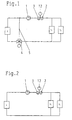
- FIGS 1 to 4 show differently constructed hydraulic systems various arrangements of elements therein. It is the location a throttle valve equipped with an actuator in different Pipeline lines shown. Devices for measuring, controlling and regulating are not shown in these figures 1 to 4.
- a simple hydraulic system in which a generator E, which depending on the system structure as a heat source or heat sink works, is equipped with a pump 1, which is a fluid within the hydraulic system circulates.
- the path from Producer E referred to consumers V1, V2 as the lead and the path from the consumers back to producer E, as a return.
- a throttle valve 2 with electronic volume flow measuring unit 3 be arranged in the forward or in the return.
- One from a 3-way valve 4 influenced admixing line 5 enables a fluid portion to be fed in the return to the forward.
- the 3-way valve 4 is also among others Known terms.
- a throttle valve 2 with Electronic volume flow measuring unit 3 is in the lead of the hydraulic one Systems arranged.
- FIG. 2 differs from FIG. 1 in that it is missing Mixing line and the missing 3-way valve.
- the missing 3-way valve Here is one out a main line existing hydraulic system shown.
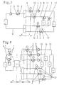
- FIG. 3 shows a hydraulic system which has several pipeline lines 6, 7 and 8. Using the vertical line and dashed lines The arrows X and Y proceeding therefrom are subdivided into those shown Pipeline strings 6 to 8 made.
- the one in area X Pipeline string 6 conducts a fluid through the generator E and is called Main strand considered.
- the pipeline strings 7, 8 located in area Y are part of the consumer community and are regarded as secondary branches.
- the pipeline string 7 in this embodiment has a consumer V1 with constant Resistor and its own pump 9, which is preceded by a 3-way valve.
- the 3-way valve acting as a mixing valve, mixes part of that Consumer V1 coming fluid to consumer V1 through a Line 10 to.
- the remaining fluid part passes through a collector SA Return to producer E back.
- the other pipeline string 8 shows in this embodiment in Parallel connection consumers V2, V3, which in this secondary line as variable Resistances work. This is due to thermostatic valves 11, which in Dependence on the room temperature TR at the location of the consumer Affect energy transfer.
- thermostatic valves 11 which in Dependence on the room temperature TR at the location of the consumer Affect energy transfer.
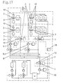
- Figure 4 shows a complex hydraulic system, which is compared to the embodiment of Figure 3 by an additional DC link Z differs.
- the producer group X has two circulation pumps 1 connected in parallel, with electronic speed control 1.7, with which the fluid to be circulated in a hydraulic switch HW is promoted.
- the pumps connected in parallel can be used separately or together or operated alternately. They improve the reliability of a such system and / or ensure the necessary circulation in full load operation the requested amount of energy.
- the hydraulic switch HW which is a connection between the here as Main circuit acting generator circuit X and the intermediate circuit Z, works as a mixer. This is explained using the example of a heater. From which the Sub-strands containing the distributor circuit Y flowing back cooler fluid collected in the collector SA and from there flows back to the colder medium hydraulic switch HW. Hotter fluid gets into the hydraulic switch HW fed by the generator E through the circulation pumps 1. Within the hydraulic switch HW is decoupled between the generator circuit and the side lines instead.
- the secondary lines are in the form of the pipeline lines 13 to 15 with throttle valves 2 and electronic volume flow measuring units 3 arranged in the return lines to the collector SA.
- the pipeline string 13 In the pipeline string 13 a parallel connection of the V3, V4 is shown. Individual consumers can too be connected in series.
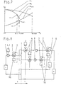
- FIG. 5 shows a circuit diagram of a transport system, which has the following components: an energy generator E, z. B. a boiler a heating system, a downstream pump 1, the promotes a volume flow to a distributor VT. Branch from distributor VT different pipeline strings 7, 8 in which consumers V1, V2 are arranged. Within consumers, which are radiators a heating system, condensers or other heat exchangers can, there is an energy release to the environment, so that from the Fluid flowing out to consumers V1, V2 has a changed energy content. A collector SA takes this from consumers V1, V2 through return lines flowing fluid on and passes it through a return line 6 the Producer E to. There, if it is a boiler, by Energy supply an increase in fluid temperature.
- a throttle valve 2 with devices 3 for electronically measuring the volume flow is arranged between pump 1 and distributor VT. It has a motorized actuator 12 and an electronic evaluation unit 16.
- the maximum permissible flow Q max for this system is stored in the evaluation unit 16. If the flow in the system is increased by reducing the resistance in consumers V1, V2 - there is an increased decrease by consumers V1, V2 - this increased flow is detected by electronic volume flow measuring unit 3 of throttle valve 2 and a corresponding signal supplied to the evaluation unit 16 in the throttle valve 2. If the volume flow reaches the range of the maximum flow rate Q max calculated and defined for this system, the flow is limited to Q max by means of a throttle and with the help of the actuator 12.
- the speed of the pump 1 is constant or is guided variably by a control 1.1.
- the pump operating point is on the pump or
- the armature 2 measures the reduction in the flow rate and, with the aid of the evaluation electronics 16, delivers an actuating signal to the servomotor 12, which takes back the existing throttling of the armature , This results in a flatter characteristic.
- the pump works for this flow rate in a more favorable operating point. With smaller flow rates Q than a stored Q opt or Q max , there are therefore no additional losses in the valve 2, since the valve 2 is then held in the fully open position. The valve's limiting function therefore only becomes active when the maximum flow rate Q max permitted for the respective pump is reached.
- a temperature sensor 17 With the aid of which the flow temperature between pump 1 and distributor VT is measured, it is possible in a simple manner to provide such a limitation of the volume flow even during an operating state in which the flow temperature is lowered.
- a characteristic curve is stored in the evaluation unit 16, which limits the delivery rate in relation to the flow temperature. With the help of this function it is possible to counteract the behavior of thermostatic valves 11, which are arranged on the consumers V1, V2, with this fitting.
- This function enables optimum energy savings in circulation pumps that are equipped with infinitely variable speed control 1.1: With such pumps, there is differential pressure control in which the pressure in front of and behind the pump is recorded and the differential pressure is either kept constant or as a function of the flow rate , The pump then only circulates the volume flow actually required and an unnecessarily high volume flow is avoided by changing the throttling effect of the valve.
- the Mass flow or the flow rate can be determined. This is done by assignment the fluid density to the volume flow.
- the Evaluation unit 16 For those applications in which an autonomous flow limitation in Transport system by throttling the valve 2 is not desired, the Evaluation unit 16 a differential pressure setpoint dependent on the flow temperature produce.
- This variable head value either a control pump with integrated ⁇ P control or specified as a reference variable in a conventional pump control system. In these cases, the control pump has a corresponding setpoint input.
- pump 1 is shown with a dashed line in FIG shown controller 1.2 equipped.
- FIG. 6 shows the use of the armature 2 as a protective device for pumps 1 in parallel operation.
- a check valve 18 prevents backflow through the second pump.
- FIG. 7 shows a QH diagram with the characteristic curves of the two pumps from FIG. 6. Furthermore, a control characteristic curve RK of the piping system which is supplied by the two pumps is shown therein.
- the pump characteristic curve PKL-1 drawn with a thick line corresponds to the individual characteristic curve of a pump.
- the PKL-2 line is the corresponding characteristic for the parallel operation of two pumps. These characteristics correspond to an operating state in which the associated throttle valves are fully open. Since the delivery data of the two pumps 1 are known, the additional losses H V, valve generated by temporarily throttling the valves are selected such that the pumps assume an operating point with the control characteristic RK.
- a throttle characteristic with at least two characteristic points is stored in the valve's evaluation unit.
- the throttle valve detects a value during the measurement of the flow rate, which corresponds to the stored flow rate Q limit , then the throttle valve 2 driven by the servomotor 12 and due to the signal supplied by the evaluation unit 16 will switch to the active throttle mode.
- the pressure loss of the valve H V, valve is based on two constants A, B and the flow rate, whereby the exponent can be in the range 0.1 to 3.
- FIG. 8 corresponds to that in FIG. 5.
- the consumer strands i.e. H. in the flow direction of the transport system from distributor VT to collector SA
- Throttle valves 2 with volume flow measuring device 3 and motorized Integrated actuator.
- the strands 7 and 8 are between pre and Return connected by temperature-controlled mixing valves 4.
- At the Start-up operation of such an energy supply system e.g. B. in the form of a Heating system, there is first an increase in the flow temperature in the flow. Since a start-up operation usually cools the consumers V1 to V2 has preceded, there is a high on the part of the individual consumer Mass flow or flow on.
- the throttle valves 2 in its evaluation unit 16 set so that it for the respective strand 7, 8th between an individually adjustable minimum and maximum Throttle the flow temperature actively. This prevents that in the producer cycle arranged pump 1 the high-energy fluid in start-up mode with overload promotes. Also, with the help of those taking place during start-up Throttling in the respective secondary lines of the consumer side Distribution circuits a systematically favorable division of the energy-rich Fluids on the individual consumers V1, V2 guaranteed.
- an additional time delay can be provided.
- Such Additional function is used to adapt to the operational rise times of a Producer, e.g. B. a boiler and is the evaluation unit 16 of the throttle valve 2 integrated.
- Fig. 9 shows a transport system in which in the return of a consumer circuit a throttle valve 2 with electronic volume flow measuring unit 3 and evaluation unit 16 is installed. Furthermore, this armature 2 additionally a temperature sensor TRL to record the return temperature before Collector SA on.
- This valve 2 has the function of a line regulating valve, with their help for full load operation an even supply of Consumer V1 to V2 is guaranteed.
- this fitting measures 2 permanently the existing actual flow and registers the return temperature TRL of the fluid.
- the valve itself remains in the line balance set, partially throttled state. It corresponds to a state like it is generated during the usual static string adjustment.
- the evaluation unit 16 connected to the armature 2 enables by means of the continuous flow and temperature measurement a calculation of the hydraulic Required in the associated pipeline. Using the calculated The evaluation unit 16 delivers a signal to a Pump control unit 1.1, which changes the speed of the pump. Because the for an entire plant most important, possibly all strands, in the same way react, only needs to be ensured with the pump control unit 1.1, that the largest reported by the evaluation unit 16 of the throttle valve 2 Need is just reached. The others just hinted at here Pipe lines 8, 9 are in the same way with the throttle valve 2 equipped and connected to the pump control 1.1. Such a control characteristic a pump 1 ensures that no string is undersupplied, but there is also no unnecessary oversupply with its adverse effects.
- the calculation of the need required for the strand can be expedient with fuzzy control. To do this, between the extreme values a large flow rate and a high return temperature as well a small flow rate in the line with low return temperature various Intermediate values, with the help of which, taking into account a a trend assessment over time becomes possible. So that's it Evaluation unit possible to send a signal to the pump controller due to whose decision is made in the controller whether the momentary delivered by the pump Head should be kept, increased or decreased. This corresponds approximately a three-point behavior of a controller.
- the valve connected to the pump control which is arranged in the return of the transport system, roughly determines the load state of the upstream consumers via the measured return temperature T R. This is based on the assumption that if the return temperature is low, consumers will also have a correspondingly low load.
- a trend can be determined which allows the load condition of the transport system to be calculated with sufficient accuracy. This has the advantage that the pump always only delivers the necessary hydraulic power that is necessary for trouble-free operation of the downstream consumers.
- the throttle valve 2 In a special operating state, in which a very low load with high pump pressure can cause over-supply of the strands that are arranged near the pump. To do this to avoid, the throttle valve 2 is additionally dashed stand-alone drive 12 equipped.
- the evaluation unit 16 of the Throttle valve 2 calculates the required target flow and causes whose exceeding an intervention with the help of the drive 12. Die Throttle valve 2 is thus partially closed, causing throttling takes place, which prevents the target flow from being exceeded or corrected.
- a control scheme is shown in which a pump 1 with flow dependent Setpoint correction is used.
- the consumer side in the return the valve SA arranged armature 2 acts as an autonomous flow control device.
- the measurement of the volume flow Q and the return temperature TRL is converted into a control signal in the evaluation unit, which is a Control signal to the motor of the valve throttle body delivers. So only at if the target flow is exceeded, the return is throttled performed.
- the pump which is regulated depending on the flow rate, registers the change of hydraulic resistance and can be used with sufficient accuracy provide the transport system with the necessary delivery head.
- FIG. 11 shows a circuit of a transport system in which the speed of two pumps operated in parallel can be changed by a frequency shaper 22.
- a differential pressure detection ⁇ P the pressure conditions upstream and downstream of the pumps 1 are recorded and fed to a pump control system 19 with a controller 23.
- the speed of the pump is changed as required in accordance with the control requirements stored there.
- a throttle valve 2 with volume flow detection 3 and actuator 12 is shown in the so-called flow of the transport system, ie on the pressure side of the pumps.
- the evaluation unit 16 supplies a volume flow signal Q via a signal line 20 to a setpoint generator 21.
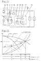
- FIG. 12 shows the possible change in the system characteristics in one System according to Figure 11.
- Figure 12 shows the operation of the pump control system with a known control curve RK dependent on the flow rate.
- the Consumer V1, V2 a larger volume flow to meet their power requirements to satisfy. This high volume flow is undesirable.
- the throttle valve 2 with flow temperature measurement and volume flow measurement, Evaluation unit 16 and control device are now determined by measuring the Flow temperature alternatively the outside temperature of the reduced state or Partial load condition. It now also throttles the volume flow behind the Pump a so that at a flow temperature of z. B. 80 ° C the operating point BP2 is enforced. If the flow temperature continues to drop to 60 ° C, additional throttling of the valve 2 finally the operating point BP3 enforced.
- FIG. 13 shows a distributor circuit Y of a transport system in the form of a hot water heating system.
- the pump 9 in the line 7 takes the fluid from the distributor VT and returns it to a collector SA via the consumers V1, V2.
- the independent control behavior in a distribution circuit of a larger energy distribution system with a large number of secondary lines is shown, which are not shown for reasons of better clarity, but are only indicated.
- the heat output is adjusted by regulating the flow temperature by adding generally cooler fluid from the return.
- the flow temperature is regulated depending on the outside temperature T A.
- a pump 9 distributes the fluid to the individual consumers V1, V2.
- Such a solution with separate circulation pumps 9 in secondary lines 7 is often used in large heating systems. They usually consist of many parallel strings, each of which supplies individual parts of the building.
- a shut-off valve 25 is arranged in the flow line of the secondary line 7 for the purpose of shutting off the entire line, a corresponding shut-off valve 26 also being located in the return line.
- a 3-way mixing valve 4 is installed in the flow line upstream of the pump, which, depending on the outside temperature T A, ensures that colder return fluid is mixed into the flow line through line 10.
- a pump 9 is arranged downstream of the mixing valve 4 and a throttle valve 2 with an electronic volume flow sensor 3 is arranged in the flow line on the pressure side of the pump 9. The sensor is preferably integrated in the throttle valve 2.
- a motorized actuating device 12 for the throttle valve 2 has proven to be advantageous.
- the consumers V1, V2 with associated thermostatic valves 11 ensure energy delivery at the location of the consumers V1, V2.
- the fluid then flows from the consumers V1, V2 through the return line back to the collector SA.
- the throttle valve 2 with the volume flow sensor 3 can also be arranged in the return line as well. This would be a cheaper place to use sensors that rely on a necessary inlet section for volume flow measurement.
- the energy requirement of the consumers is primarily dependent on the outside temperature T A , which is why the outside temperature T A is used to regulate the flow temperature T V in the flow line.
- the 3-way mixing valve 4 mixes return water from the return line via the bypass 10 and supply fluid from the supply until the supply temperature T V assigned to the prevailing outside temperature T A is reached.
- the energy consumption of the consumers V1, V2 at the locations to be heated is practically exclusively dependent on the temperature difference between the consumer and the ambient air and the heat transfer to the air side.
- the amount of fluid flowing through the consumers V1, V2 has only a negligible influence on the radiators usually used.
- the fluid circulating in the system primarily has the task of transporting the required energy, in the present case as the required amount of heat. This is proportional to the product of fluid quantity and fluid cooling.
- This thermal engineering law allows, in parallel to a regulation of the flow temperature TV, a regulation of the circulated flow rate, while maintaining the desired control quality.
- FIG. 14 shows this using the control characteristic curves RK for a speed regulated pump.
- the operating point is B
- an inventive Transport system with variable delivery rate is due to the medium annual outside temperature the flow rate at operating point A.
- Influences from thermostatic valves or night and weekend reductions are not considered.
- FIG. 13 the representation in FIG Mixing valve 4 replaced by two throttle valves 2.1, 2.2 with actuator 12.
- the Throttle valve 2.1 is in the flow line before the confluence of an admixture line 10 arranged, the admixture line 10 a second throttle valve 2.2 has.
- Such an arrangement is less expensive than that in FIG. 13 Shown combination of 3-way mixing valve 4 and a throttle valve 2. Die Functionality of the two throttle valves 2.1, 2.2 used here is analog the functionality of the embodiment in FIG. 13.
- An electronic evaluation unit 29 coordinates in this exemplary embodiment the interaction of the individual parts, the information about the Volume flow from the two throttle valves via the integrated Volume flow sensor 3.1, 3.2 can be supplied.
- the throttle valve 2.2 can be the same in a simple embodiment Functionality can also be replaced by a spring-loaded relief valve, whereby a further cost reduction is achieved.
- FIG. 16 shows a diagram of a heating system which is used for a Flow temperature of 90 ° Celsius, a return temperature of 70 ° Celsius and a room temperature to be reached of 20 ° Celsius was designed. Becomes such a system in a conventional manner with a constant flow rate operated, this corresponds to the horizontal flow characteristic a. He follows on the other hand, a reduction in the flow rate in the partial heat load range, then delivery characteristics according to the invention are obtained, e.g. the one shown Flow characteristic b. The diagram shows that only one a few degrees increase in the flow temperatures by the value x, there is a significant reduction in the delivery rate by the amount y.
- the Curves c drawn with dashed lines are curves of the same thermal output Radiator or the consumer.
- FIG. 17 shows a transport system which consists of several together hydraulically coupled, but exemplarily with only two strands 7 shown, 8 exists.
- An example of a large heating system is described in which the heat output of several generators E1 of a certain size, E2 is divided.
- the producers are several in parallel switched boiler, with the interposition of a hydraulic switch HW are connected to an intermediate circuit.
- the intermediate circuit has that Task, the energy-rich fluid supplied by the generator circuit to several Distribute consumer circuits 7, 8.
- an im Intermediate circuit pump 30 arranged the fluid in a flow distributor VT, from which the flow lines of the various - in the embodiment only 2 strands are supplied for reasons of space. From the strands the low-energy fluid flows to a common return collector SA Intermediate circuit to from where it goes to the hydraulic switch HW flowing back.
- throttle fittings 2 with devices 3 for electronic volume flow detection being arranged in the individual lines or circuits.
- These fittings are connected to a central controller unit 28, into which they feed the permanently measured volume flows.
- the controller 28 in turn supplies control signals to the servomotors 12 of the throttle valves 2, in order to carry out a temporary throttling in the respective consumer branch or in the intermediate circuit, which is adapted to the required amount of energy or heat output, depending on the flow T V or outside temperature T A.
- the quantity in the intermediate circuit is adjusted to the total quantity of consumer strands. By additionally recording the temperature at the location of the quantity measurement, a direct energy-saving optimization of the circulated heat quantity is possible.
- the consumer line 8 shows an embodiment in which a single Line pump 9.2 supplies several lines.
- Throttle valves 2 with actuator 12 and electronic flow measurement can by their connection with the control unit 28, the stability of the consumer control system, e.g. their thermostatic radiator valves, improve.
- Flow rate can be with a too large pressure drop over the consumers part of the unwanted differential pressure by changing the throttle body be dismantled in the valve.
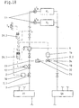
- FIG. 18 shows a consumer circuit 7 as a secondary branch of a hydraulic transport system is formed.
- This subsidiary line is from fed a distributor VT and ends in a collector SA.
- the control system consists of a throttle valve 2 and a regulated pump 9 consumers V1, V2 with thermostatic valves 11.
- a directly assigned to the consumers Volume flow measuring unit 3.1 is after the distributor VT and before the pump 9 arranged.
- the bypass 10 connects the consumer V1, V2 leading part of the strand 7, the return, with which the pump 9th containing lead.
- a further volume flow measuring unit 3.2 is arranged in the bypass 10 and a valve31, which as a manually operated throttle valve, as a - as shown - spring-loaded check valve or designed as an overflow valve can be.
- the volume flow measuring unit 3.1 measures a volume flow Q1 and the volume flow measuring unit 3.2 a volume flow Q2.
- the addition of Q1 and Q2 gives the total volume flow Q to be circulated by the pump 9.
- the volume flows recorded by the volume flow measuring units 3.1, 3.2 are fed as electronic measurement signals to a controller 29.1, in which a Setpoint of the flow temperature and the actual temperature Tv of the flow line is fed.
- controller 29.1 supplies the corresponding control signals to throttle valve 2 and to the speed-controllable pump 9.
- controller 29.1 supplies the corresponding control signals to throttle valve 2 and to the speed-controllable pump 9.
- the still drawn, but not numbered valve symbols are used to shut off line 7 or for disassembly of the pump 9.
- the controller 29.2 .... shown here as a separate part detects the outside temperature T A and, alternatively to the controller 29.1, possibly also the actual value of the flow temperature.
- the controller 29.1 processes the signals supplied by the volume flow measuring units 3.1 and 3.2 as well as the flow temperature and regulates the circulation pump 9 and the throttle valve accordingly.
- the two controllers 29.1 and 29.2 can also be combined to form a common structural unit, see FIG. 15.
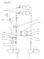
- the embodiment of FIG. 19 differs from that Embodiment of FIG. 18 by the arrangement of throttle valves 2.1 and 2.2.
- the throttle valve 2.2 is arranged in the bypass line 10.
- the controller 29.1 depending on the signals that the Deliver volume flow measuring units 3.1 and 3.2 with the help of the throttle valves 2.1 and 2.2 the volume flow Q1 and Q2 according to the needs of the Consumers V1 and V2 are regulated.
- the corresponding sub-flows are very accurate Detected way and thus allow a very precise control.
- the arrangement of the Volume flow units 3.1 and 3.2 are not limited to the illustration. So will in another arrangement of the volume flow measuring unit 3.2, for example in the part of the strand 7 which serves as the return, another volume flow detected. With an arrangement after the consumer V2 and before the branch point 34 of the bypass line 10, the entire volume flow Q is detected while in an arrangement after the branch point 34 of the bypass line 10 and, before the collector SA reduced by the amount Q2 of the bypass line Volume flow is measured. By adding or Subtraction processes within the controller 29.1 can thus be caused by the pump 9 volume flow to be circulated and the partial volume flows Q1 Q2 exactly be determined.
- a shut-off valve is advantageously used as the volume flow measuring unit 3.1, 3.2 with throttle function and integrated electronic volume flow sensor Use.
- the arrangement in the bypass line 10 can on the use of an additional throttle valve mentioned in relation to FIG. 18 be forgiven.
- FIG. 20 shows an embodiment in which the function of the in the 18 and 19 shown controller 29.1 in the drives 12.2 of the throttle valves 2.1 and 2.2 is integrated.
- the data supplied in 3.1 and 3.2 is regulated by the throttle valves 2.1, 2.2 and possibly also the pump 9.
- An integration of the controller shown in the other exemplary embodiments can also be found there in the respective drives take place. It is also easily possible in the Embodiments shown controller in the pump control 1.1 integrate.
Landscapes
- Engineering & Computer Science (AREA)
- Physics & Mathematics (AREA)
- Thermal Sciences (AREA)
- Chemical & Material Sciences (AREA)
- Combustion & Propulsion (AREA)
- Mechanical Engineering (AREA)
- General Engineering & Computer Science (AREA)
- Flow Control (AREA)
- Pipeline Systems (AREA)
- Fluid-Pressure Circuits (AREA)
Description
- Fig. 1-4
- verschiedene vereinfachte Darstellungen von hydraulischen Systemen, die
- Fig. 5
- eine Anordnung einer Armatur als Überlastschutz einer Pumpe, die
- Fig. 6
- eine Schutzeinrichtung für parallel betriebene Pumpen, die
- Fig. 7
- ein zur Fig. 6 gehöriges Q,H-Diagramm, die
- Fig. 8
- eine Schutzeinrichtung für Pumpen in Anfahrbetrieb mit zeitweiliger Überlast, die
- Fig. 9
- eine aktive Regulierung in Rohrleitungssträngen von Transport-systemen hydraulischer Flüssigkeiten, die
- Fig. 10
- eine von einer Pumpenregelung unabhängige aktive Strangregulierung in einem Verbraucherstrang, die
- Fig. 11
- eine Pumpenleistungsanpassung durch Volumenstromführung, die
- Fig. 12
- ein zur Fig. 11 gehöriges Q,H-Diagramm, die
- Fig. 13
- eine Regelung eines Verbraucherstranges einer Heizungsanlage mit Außentemperaturerfassung und Mischventil, die
- Fig. 14
- eine zur Fig. 13 gehörige Regelkennlinie eines Q,H-Diagrammes, die
- Fig. 15
- eine Variante von Fig. 13, in der das Mischventil ersetzt wurde, die
- Fig. 16
- ein Auslegungsdiagramm für eine Heizungsanlage, die
- Fig. 17
- eine Großanlage, die
- Fig. 18 + 19
- eine Anordnung mit zwei Volumenstrommeßeinheiten und die
- Fig. 20
- eine Integration eines Reglers in Anlagekomponenten.
Durch einen Temperatursensor 17, mit dessen Hilfe die Vorlauftemperatur zwischen Pumpe 1 und Verteiler VT gemessen wird, ist es in einfacher Weise möglich, eine solche Begrenzung des Volumenstroms auch während eines Betriebszustandes vorzusehen, in dem die Vorlauftemperatur abgesenkt wird. Zu diesem Zweck wird in die Auswerteeinheit 16 eine Kennlinie hinterlegt, welche die Fördermenge in bezug auf die Vorlauftemperatur begrenzt. Mit Hilfe dieser Funktion ist es möglich, mit dieser Armatur dem Verhalten von Thermostatventilen 11, die an den Verbrauchern V1, V2 angeordnet sind, entgegenzuwirken. Diese Funktion ermöglicht eine optimale Energieeinsparung bei Umwälzpumpen, die mit einer stufenlosen Drehzahlregelung 1.1 ausgestattet sind: Bei solchen Pumpen erfolgt eine Differenzdruckregelung, in dem der Druck vor und hinter der Pumpe erfaßt wird und der Differenzdruck entweder konstant oder als Funktion von der Fördermenge variabel gehalten wird. Die Pumpe wälzt dann nur den tatsächlich notwendigen Volumenstrom um und ein unnötig hoher Volumenstrom durch Veränderung der Drosselwirkung der Armatur wird vermieden.
ist sichergestellt, daß eine einzelne Pumpe durch die im zugehörigen Rohrleitungsstrang angeordnete Drosselarmatur 2 immer nur vorübergehend gedrosselt wird. Im jeweiligen Normalbetrieb bis zur Nennfördermenge sind die Drosselarmaturen 2 vollständig geöffnet und gewährleisten dadurch einen verlustarmen Betrieb des Transportsystems. Durch die dynamische Durchflußmengenbegrenzung mittels Drosseln ist der Einsatz von Umwälzpumpen möglich, deren Leistungsdaten gegenüber den bisherigen Auslegungsarten knapper dimensioniert sind. Ebenso kann für eine Pumpenregelanlage im Teillastbetrieb eine Reduzierung der Förderhöhe vorgenommen werden, wodurch wiederum eine Energieeinsparung möglich wird. Der zwischen den Punkten P1 und P2 zeitweilig gegebene Kennlinienverlauf ist als PKLGrenz bezeichnet. Dieses Verhalten gilt entsprechend für den gleichzeitigen Betrieb beider Pumpen gemäß Fig. 6.
Claims (28)
- Transportsystem, mit einem flüssigen Fluid zur thermischen Energieübertragung, wobei mindestens eine Pumpe in einem hydraulischen System ein Fluid zwischen Erzeuger und Verbraucher unter Überwindung von Rohrnetzwiderständen zirkulierend umwälzt, die Verbraucher in dem hydraulischen System variable oder feste Widerstände darstellen und eine Einrichtung zur Beeinflussung der Wärmetransportleistung, insbesondere über eine Veränderung einer Vorlauftemperatur im hydraulischen System, angeordnet ist, dadurch gekennzeichnet, daß in einem Hauptstrang und/oder in mindestens einem Nebenstrang des hydraulischen Systems eine Drosselarmatur (2) mit elektronischer Volumenstrommeßeinheit (3) eingebaut ist, daß der gemessene Volumenstrom als Istwert in eine Steuereinrichtung, eine Regeleinrichtung (19, 24) oder eine Auswerteeinheit (16) einfließt, daß die Auswerteeinheit (16) eine Führungsgröße für die Regeleinrichtungen (23, 24) liefert und daß die Regeleinrichtung (23, 24) über eine Stelleinrichtung (12, 22) die Drehzahl der Pumpe (1, 9, 31) und/oder die Drosselstellung einer oder mehrerer Drosselarmaturen (2, 2.1, 2.2) verändert.
- Transportsystem nach Anspruch 1, dadurch gekennzeichnet, daß die Drosselarmatur (2, 2.1, 2.2) und/oder die elektronische Volumenstrommeßeinheit (3) mit einem Temperatursensor versehen ist.
- Transportsystem nach Anspruch 1 oder 2, dadurch gekennzeichnet, daß die Drosselarmatur (2, 2.1, 2.2) mit einem Stellantrieb (12) versehen ist.
- Transportsystem nach Anspruch 3, dadurch gekennzeichnet, daß die elektronische Auswerteeinheit (16) der Drosselarmatur (2, 2.1, 2.2) mit einem die Temperatur innerhalb oder außerhalb des hydraulischen Systems erfassenden Temperatursensor verbunden ist.
- Transportsystem nach Anspruch 4, dadurch gekennzeichnet, daß der Temperatursensor die Vorlauf- und/oder Rücklauftemperatur des hydraulischen Systems erfaßt.
- Transportsystem nach einem der Ansprüche 1 bis 5, dadurch gekennzeichnet, daß eine oder mehrere Drosselarmaturen (2, 2.1, 2.2) mit integrierter elektronischer Volumenstrommeßeinheit (3) und Auswerteeinheit (16) in Erzeugerkreisläufen, Zwischenkreisläufen und/oder Verbraucherkreisläufen des Transportsystemes angeordnet sind.
- Transportsystem nach einem der Ansprüche 1 bis 6, dadurch gekennzeichnet, daß die Drosselarmatur (2, 2.1, 2.2) den Pumpenförderstrom überwacht und bei gemessenen Abweichungen von einer vorgegebenen Regelkennlinie durch temporäres Verändern der Durchflußmenge den Arbeitspunkt der Pumpe (1) verschiebt.
- Transportsystem nach einem der Ansprüche 1 bis 7, dadurch gekennzeichnet, daß die Drosselarmatur (2, 2.1, 2.2) den Volumenstrom eines Stranges (7, 8) erfaßt, daß bei Überschreitung von in die Auswerteeinheit (16) und/oder die Regeleinrichtung (24) vorgegebenen Volumenstromwerten ein Drosseln des momentanen Volumenstromes erfolgt.
- Transportsystem nach einem der Ansprüche 1 bis 8, dadurch gekennzeichnet, daß in der elektronischen Auswerteeinheit (16) der Drosselarmatur (2, 2.1, 2.2) mehrere Kennlinienpunkte und/oder Kennlinienkurven zur Generierung einer Führungsgröße für die Regeleinrichtung (23) hinterlegt sind.
- Transportsystem nach einem oder mehreren der Ansprüche 1 bis 9, dadurch gekennzeichnet, daß Auswerteeinheit (16) und Regeleinrichtung (24) integriert sind.
- Transportsystem nach dem Oberbegriff von Anspruch 1, wobei die Pumpe drehzahlgeregelt ist, Einrichtungen zur Beeinflussung der Wärmetransportleistung im hydraulischen System angeordnet sind und durch mindestens eine zwischen einer Vorlaufleitung und einer Rücklaufleitung angeordnete Bypassleitung eine verbraucherseitige Veränderung einer Vorlauftemperatur im hydraulischen System erfolgt, dadurch gekennzeichnet, daß in einem Hauptstrang und/oder in mindestens einem Nebenstrang des hydraulischen Systems mindestens eine Drosselarmatur (2) in Kombination mit einer elektronischen Volumenstrommeßeinheit (3) eingebaut ist, daß der gemessene Volumenstrom in eine Steuer- oder Regeleinrichtung (24, 27, 28, 29 - 29.2) einfließt, daß eine gemessene Vorlauf- und/oder Rücklauftemperatur TV, TRL in die Steuer- oder Regeleinrichtung (24, 27, 28, 29 - 29.2) einfließt und daß die Steuer- oder Regeleinrichtung (24, 27, 28, 29 - 29.2) über eine Stelleinrichtung (12, 12.2) die Drosselstellung einer oder mehrerer Drosselarmaturen (2, 2.1, 2.2) verändert.
- Transportsystem nach einem oder mehreren der Ansprüche 1 bis 11, dadurch gekennzeichnet, daß die Steuer- oder Regeleinrichtung (24, 27, 28, 29 - 29.2) über eine Stelleinrichtung (1.1, 1.2, 20) die Drehzahl der Pumpe (1, 9 - 9.2) verändert.
- Transportsystem nach Anspruch 12, dadurch gekennzeichnet, daß die Stelleinrichtung (1.1, 1.2, 20) als elektrische Stelleinrichtung ausgebildet ist.
- Transportsystem nach einem oder mehreren der Ansprüche 1 bis 13, dadurch gekennzeichnet, daß die Steuer- oder Regeleinrichtung (24, 27, 28, 29 - 29.2) über Stelleinrichtungen (1.1, 1.2, 12, 12.2, 20) die Drosselstellung einer oder mehrerer Drosselarmaturen (2, 2.1, 2.2) und die Drehzahl der Pumpe (1, 9 - 9.2) verändert.
- Transportsystem nach einem oder mehreren der Ansprüche 1 bis 14, dadurch gekennzeichnet, daß in dem hydraulischen System, in dem mindestens eine Drosselarmatur (2) in Kombination mit einer elektronischen Volumenstrommeßeinheit (3, 3.1, 3.2) eingebaut ist, eine selbstregelnde Pumpe mit vom Förderstrom abhängigen Förderhöhensollwert angeordnet ist.
- Transportsystem nach einem oder mehreren der Ansprüche 1 bis 15, dadurch gekennzeichnet, daß eine elektronische Volumenstrommeßeinheit (3 - 3.2) in den Verbraucherkreisläufe (7, 8) im Bereich vor einem ersten Verbraucher V1 oder nach einem letzten Verbraucher Vx und zwischen den Einmündungsorten (33, 34) der Bypassleitung (10) angeordnet ist.
- Transportsystem nach einem oder mehreren der Ansprüche 1 bis 16, dadurch gekennzeichnet, daß in einem mit einer Bypassleitung (10) ausgerüsteten Verbraucherkreislauf (7) mindestens zwei Volumenstrommeßeinheiten (3, 3.1, 3.2) angeordnet sind.
- Transportsystem nach Anspruch 17, dadurch gekennzeichnet, daß eine der Volumenstrommeßeinheiten (3 - 3.2) einen Teilstrom des gesamten Förderstromes erfaßt.
- Transportsystem nach einem oder mehreren der Ansprüche 1 bis 18, dadurch gekennzeichnet, daß in der Bypassleitung (10) eine Absperrarmatur mit Drosselfunktion (32) angeordnet ist.
- Transportsystem nach einem oder mehreren der Ansprüche 1 bis 18, dadurch gekennzeichnet, daß in der Bypassleitung (10) eine federbelastete Überströmarmatur (32) oder ein Rückflußverhinderer (31) angeordnet ist.
- Transportsystem nach einem oder mehreren der Ansprüche 1 bis 20, dadurch gekennzeichnet, daß die Auswerteeinheit (16) aus dem Signal der Volumenstrommeßeinheit (3 -3.2) eine Führungsgröße für die Steuer- oder Regeleinrichtung (24, 27, 28, 29 - 29.2) liefert.
- Transportsystem nach Anspruch 21, dadurch gekennzeichnet, daß in der Auswerteeinheit (16) Grenzwerte für die Steuer- oder Regeleinrichtung (24, 27, 28, 29 - 29.2) gespeichert sind.
- Transportsystem nach Anspruch 21 oder 22, dadurch gekennzeichnet, daß in der Auswerteeinheit (16) die Werte für einen maximalen Volumenstrom Qmax gespeichert sind.
- Transportsystem nach Anspruch 21, 22 oder 23, dadurch gekennzeichnet, daß Führungsgrößen, Grenzwerte und der maximale Volumenstrom Qmax in mindestens einer Auswerteeinheit (16) und/oder in der Steuer- oder Regeleinrichtung (24, 27, 28, 29 - 29.2) gespeichert sind.
- Transportsystem nach einem der Ansprüche 1 bis 24, dadurch gekennzeichnet, daß die elektronische Volumenstrommeßeinheit (3 - 3.2) über einen Sensor und eine Auswerteeinheit (16) verfügt und daß die Auswerteeinheit (16) aus dem Sensorsignal ein Volumenstromsignal bildet.
- Transportsystem nach einem der Ansprüche 1 bis 24, dadurch gekennzeichnet, daß die Auswerteeinheit (16) die von der Volumenstrommeßeinheit (3 - 3.2), einem zusätzlichen Temperatursensor oder von anderen Sensoren gelieferten Eingangssignale in elektronische Ausgangsgrößen für die Regel- und Steuereinrichtung (24, 27, 28, 29 - 29.2)umsetzt.
- Transportsystem nach einem der Ansprüche 1 bis26, dadurch gekennzeichnet, daß die Auswerteeinheit (16) über mindestens einen Microprozessor und hinterlegte Kennlinien, Einstellwerte, Algorithmen oder Fuzzy-Regeln zur Beeinflussung der Steuer- oder Regeleinrichtung (24, 27, 28, 29 - 29.2)verfügt.
- Transportsystem nach einem der Ansprüche 1 bis 26, dadurch gekennzeichnet, daß die Steuer- öder Regeleinrichtung (24, 27, 28, 29 - 29.2) über mindestens einen Microprozessor und hinterlegte Kennlinien, Einstellwerte, Algorithmen oder Fuzzy-Regeln zur Beeinflussung des hydraulischen Transportsystems verfügt.
Applications Claiming Priority (3)
| Application Number | Priority Date | Filing Date | Title |
|---|---|---|---|
| DE19912588A DE19912588A1 (de) | 1999-03-20 | 1999-03-20 | Fluidtransportsystem |
| DE19912588 | 1999-03-20 | ||
| PCT/EP2000/002326 WO2000057111A1 (de) | 1999-03-20 | 2000-03-16 | Fluidtransportsystem |
Publications (2)
| Publication Number | Publication Date |
|---|---|
| EP1163478A1 EP1163478A1 (de) | 2001-12-19 |
| EP1163478B1 true EP1163478B1 (de) | 2004-05-26 |
Family
ID=7901763
Family Applications (1)
| Application Number | Title | Priority Date | Filing Date |
|---|---|---|---|
| EP00916959A Expired - Lifetime EP1163478B1 (de) | 1999-03-20 | 2000-03-16 | Fluidtransportsystem |
Country Status (5)
| Country | Link |
|---|---|
| EP (1) | EP1163478B1 (de) |
| AT (1) | ATE267988T1 (de) |
| DE (2) | DE19912588A1 (de) |
| DK (1) | DK1163478T3 (de) |
| WO (1) | WO2000057111A1 (de) |
Cited By (2)
| Publication number | Priority date | Publication date | Assignee | Title |
|---|---|---|---|---|
| EP2157376A2 (de) | 2008-08-23 | 2010-02-24 | Honeywell Technologies Sarl | System zum Kühlen oder Heizen und Anordnung zum hydraulischen Abgleichen eines wasser- oder dampfführenden Systems zum Kühlen oder Heizen |
| EP2910861A1 (de) | 2014-02-25 | 2015-08-26 | Honeywell Technologies Sarl | System zum kühlen oder heizen und Anordnung zum abgleichen eines wasser- oder dampfführenden Systems zum kühlen oder heizen |
Families Citing this family (31)
| Publication number | Priority date | Publication date | Assignee | Title |
|---|---|---|---|---|
| DE50205869D1 (de) * | 2001-12-21 | 2006-04-27 | Ksb Ag | Hydraulische Anlage |
| DE10163987A1 (de) * | 2001-12-24 | 2003-07-10 | Grundfos As | Verfahren zum Steuern einer drehzahlregelbaren Heizungsumwälzpumpe |
| DE10163989A1 (de) * | 2001-12-24 | 2003-07-10 | Grundfos As | Verfahren zum Steuern einer drehzahlregelbaren Heizungsumwälzpumpe |
| DE10348536B4 (de) * | 2003-10-18 | 2023-02-02 | Roland Sailer | Anordnung zur Erwärmung von Brauchwasser |
| DE102004017593B3 (de) | 2004-04-07 | 2005-11-03 | Albert Bauer | Kühl- und/oder Heizvorrichtung |
| DE102006041345A1 (de) * | 2006-09-01 | 2008-03-13 | Wilo Ag | Verfahren zum Betrieb eines Rohrnetzes |
| DE102007058211A1 (de) * | 2007-12-04 | 2009-06-10 | Siemens Ag | Verfahren zum Betrieb eines strömungstechnischen Leitungssystems |
| PL2307938T3 (pl) | 2008-06-26 | 2014-02-28 | Belparts | Układ regulacji przepływu |
| US8109289B2 (en) * | 2008-12-16 | 2012-02-07 | Honeywell International Inc. | System and method for decentralized balancing of hydronic networks |
| DE102009031944A1 (de) * | 2009-07-07 | 2011-01-13 | Holter Regelarmaturen Gmbh & Co. Kg | Wärmeleistungs- und Volumenstromregler |
| EP2354555B2 (de) | 2010-01-19 | 2019-09-25 | Grundfos Management A/S | Verfahren zur Energieoptimierung von Pumpen |
| DE102010022763A1 (de) * | 2010-06-05 | 2011-12-08 | Oventrop Gmbh & Co. Kg | Verfahren zum automatischen hydraulischen Abgleich in fluidführenden Anlagen |
| DE102011010840B4 (de) * | 2011-02-10 | 2019-08-14 | Oventrop Gmbh & Co. Kg | Trink- oder Brauchwassersystem |
| DE102011012211A1 (de) * | 2011-02-23 | 2012-08-23 | Wilo Se | Leistungsoptimiertes Betreiben einer elektromotorisch angetriebenen Pumpe durch Mitkopplung |
| CH705143A1 (de) * | 2011-06-30 | 2012-12-31 | Belimo Holding Ag | Verfahren und Vorrichtungen zum Abgleichen einer Gruppe von Verbrauchern in einem Fluidtransportsystem. |
| DE102011079732B4 (de) * | 2011-07-25 | 2018-12-27 | Siemens Aktiengesellschaft | Verfahren und Vorrichtung zum Steuern bzw. Regeln eines Fluidförderers zum Fördern eines Fluides innerhalb einer Fluidleitung |
| US9527683B2 (en) | 2011-07-25 | 2016-12-27 | Siemens Aktiengesellschaft | Method and device for controlling and/or regulating a fluid conveyor for conveying a fluid within a fluid line |
| DE102012020692A1 (de) * | 2012-10-22 | 2014-04-24 | Siemag Tecberg Gmbh | Verfahren zur Volumenstromregelung in untertägigen Bergwerkskühlanlagen |
| DE102013204607A1 (de) * | 2013-03-15 | 2014-09-18 | Thomas Stahl | Regelung eines Volumenstroms bei Pumpen bei geringen Volumenströmen |
| EP2853822A1 (de) * | 2013-09-26 | 2015-04-01 | ABB Oy | Pumpsteuerungssystem |
| EP2871424B1 (de) * | 2013-11-07 | 2018-07-18 | Grundfos Holding A/S | Regelungsverfahren für ein Heizungs- und/oder Kühlsystem sowie Verteiler-Einrichtung für ein Heizungs- und/oder Kühlsystem |
| DE102014008319B4 (de) * | 2014-05-30 | 2017-11-23 | Peter Gabanyi | Raumtemperatur-Regelung für eine Flächenheizung |
| EP2960587B1 (de) * | 2014-06-24 | 2023-06-07 | Grundfos Holding A/S | Verfahren zum Begrenzen des Versorgungsstromes in einem Wärmeübertragungssystem |
| DE102014016791B4 (de) * | 2014-11-14 | 2022-05-12 | Paw Gmbh & Co. Kg | Verfahren zur hydraulischen Regelung mehrerer Heizkreisläufe am Verteilerbalken |
| US9864383B2 (en) | 2015-04-02 | 2018-01-09 | Belimo Holding Ag | Method and system for determining characteristic parameters of a hydraulic network |
| DE102015014378A1 (de) * | 2015-11-09 | 2017-05-11 | Wilo Se | Verfahren zur Regelung einer Kreiselpumpe sowie zugehöriges Pumpensystem |
| DE102016002690A1 (de) | 2016-03-08 | 2017-09-14 | Paw Gmbh & Co. Kg | Verfahren zur hydraulischen Entkopplung mehrerer, parallel geschalteter Fluidkreisläufe |
| WO2017220263A1 (en) | 2016-06-22 | 2017-12-28 | Belimo Holding Ag | Method and devices for controlling a fluid transportation network |
| DE102016112093B4 (de) * | 2016-07-01 | 2020-08-27 | Dspace Digital Signal Processing And Control Engineering Gmbh | Verfahren zur Regelung eines Volumenstroms und Prüfstand zur Simulation eines Flüssigkeitskreislaufs |
| US20220196250A1 (en) | 2019-07-22 | 2022-06-23 | Belimo Holding Ag | Method and system for balancing a hydronic network |
| WO2023057409A1 (en) * | 2021-10-07 | 2023-04-13 | Belimo Holding Ag | Fluid transportation network and method |
Family Cites Families (10)
| Publication number | Priority date | Publication date | Assignee | Title |
|---|---|---|---|---|
| DE6801233U (de) * | 1968-10-07 | 1969-03-06 | Eugen Woerner Oeler U Fetterfa | Mengenregler, insbesondere fuer schmiermittel |
| IT1036636B (it) * | 1975-07-25 | 1979-10-30 | Ve Ma Elettropompe Spa | Perfezionamento nei mezzi per la regolazione della temperatura di ambienti particolarmente per impianti di riscaldamento a circo lazione forzata di fluido |
| DE2747969A1 (de) * | 1977-10-26 | 1979-05-10 | Braukmann Armaturen | Regelvorrichtung fuer eine heizungsanlage |
| FR2441807A1 (fr) * | 1978-11-16 | 1980-06-13 | Accumulateurs Fixes | Methode de regulation du chauffage d'une enceinte et dispositif a regulation pour le chauffage d'une enceinte |
| DE3210098A1 (de) * | 1982-03-19 | 1983-09-29 | Siemens AG, 1000 Berlin und 8000 München | Mess- und regeleinrichtung fuer den durchfluss einer fluessigkeit in einer leitung |
| DE3432494C2 (de) * | 1984-09-04 | 1995-07-27 | Buerkert Gmbh | Regelungsanordnung zur Regelung des Durchsatzes von Gas- oder Flüssigkeitsströmen in Rohrleitungen |
| DE4019503A1 (de) * | 1990-06-19 | 1992-01-02 | Heimeier Gmbh Metall Theodor | Einrichtung zur steuerung des stellventiles einer zentralheizungsanlage |
| DE4118799A1 (de) * | 1991-06-07 | 1992-12-10 | Buderus Heiztechnik Gmbh | Verfahren zur steuerung der heizwasserzirkulation in einer heizungsanlage |
| IT1276413B1 (it) * | 1995-06-06 | 1997-10-31 | Eltek Spa | Dispositivo e metodo per la regolazione= della portata di un liquido, con controllo ad anello chiuso |
| DE19725376A1 (de) | 1996-12-21 | 1998-06-25 | Klein Schanzlin & Becker Ag | Strangregulierarmatur |
-
1999
- 1999-03-20 DE DE19912588A patent/DE19912588A1/de not_active Withdrawn
-
2000
- 2000-03-16 EP EP00916959A patent/EP1163478B1/de not_active Expired - Lifetime
- 2000-03-16 DK DK00916959T patent/DK1163478T3/da active
- 2000-03-16 WO PCT/EP2000/002326 patent/WO2000057111A1/de active IP Right Grant
- 2000-03-16 AT AT00916959T patent/ATE267988T1/de active
- 2000-03-16 DE DE50006601T patent/DE50006601D1/de not_active Expired - Lifetime
Cited By (4)
| Publication number | Priority date | Publication date | Assignee | Title |
|---|---|---|---|---|
| EP2157376A2 (de) | 2008-08-23 | 2010-02-24 | Honeywell Technologies Sarl | System zum Kühlen oder Heizen und Anordnung zum hydraulischen Abgleichen eines wasser- oder dampfführenden Systems zum Kühlen oder Heizen |
| DE102008039525A1 (de) | 2008-08-23 | 2010-04-15 | Honeywell Technologies Sarl | System zum Kühlen oder Heizen und Anordnung zum hydraulischen Abgleichen eines wasser- oder dampfführenden System zum Kühlen oder Heizen |
| EP2157376A3 (de) * | 2008-08-23 | 2014-05-28 | Honeywell Technologies Sarl | System zum Kühlen oder Heizen und Anordnung zum hydraulischen Abgleichen eines wasser- oder dampfführenden Systems zum Kühlen oder Heizen |
| EP2910861A1 (de) | 2014-02-25 | 2015-08-26 | Honeywell Technologies Sarl | System zum kühlen oder heizen und Anordnung zum abgleichen eines wasser- oder dampfführenden Systems zum kühlen oder heizen |
Also Published As
| Publication number | Publication date |
|---|---|
| EP1163478A1 (de) | 2001-12-19 |
| DK1163478T3 (da) | 2004-09-20 |
| DE19912588A1 (de) | 2000-09-21 |
| DE50006601D1 (de) | 2004-07-01 |
| ATE267988T1 (de) | 2004-06-15 |
| WO2000057111A1 (de) | 2000-09-28 |
Similar Documents
| Publication | Publication Date | Title |
|---|---|---|
| EP1163478B1 (de) | Fluidtransportsystem | |
| EP2960587B1 (de) | Verfahren zum Begrenzen des Versorgungsstromes in einem Wärmeübertragungssystem | |
| EP1754004B1 (de) | Kühl- und/oder heizvorrichtung | |
| EP2870414B1 (de) | Verfahren zum betrieb eines wärmetauschers sowie hvac-anlage zur durchführung des verfahrens | |
| DE102006045028A1 (de) | Konstanttemperatur-Flüssigkeitszirkuliervorrichtung und Verfahren zur Steuerung der Temperatur in der Vorrichtung | |
| WO2013034358A1 (de) | Verfahren zum betreiben und/oder überwachen einer hvac-anlage | |
| EP2187136A2 (de) | Verfahren zum Betreiben eines Systems zum Transport thermischer Energie über ein flüssiges Medium | |
| EP0892223B1 (de) | Steuer- und Regelgerät für eine Heizungsanlage | |
| DE19859364C2 (de) | Wärmeversorgungsanlage mit Spitzenlastbegrenzung | |
| EP1191287B1 (de) | Leitungssystem zur thermischen Energieübertragung | |
| AT406081B (de) | Heizanlage | |
| EP0872788B1 (de) | Steuereinrichtung für eine Heizungs-oder Kälteanlage mit einem Pufferspeicher | |
| DE3620929A1 (de) | Verfahren und einrichtung zur regelung mindestens einer heizung | |
| AT411190B (de) | Heizanlage und/oder kühlanlage mit mindestens einer wärmequelle | |
| DE10057410C1 (de) | Zentrale Kühl- und/oder Heizvorrichtung für zumindest ein Gebäude | |
| WO2019183658A1 (de) | Konditioniereinrichtung zur regelung eines gasförmigen oder flüssigen fluids auf eine konstante solltemperatur | |
| DE10259279B3 (de) | Versorgungssystem für Heiz-oder Kühlwasser sowie Verfahren zum Betreiben desselben | |
| AT411794B (de) | Wärmeübertragereinheit mit strahlpumpe als stellorgan | |
| DE2216464A1 (de) | Steuer- und regeleinrichtung zur optimalen erfassung der waermemenge bei der messung mit waermezaehlern und waermemengenmessern | |
| DE2712110C2 (de) | Anlage zum Heizen und/oder Kühlen | |
| DE19830761C2 (de) | Warm- oder Heißwassererzeuger | |
| DE102012101850A1 (de) | Verfahren zur bedarfsgeführten Regelung eines Wärmeerzeugers in einer Heizungsanlage | |
| EP1321842B1 (de) | Hydraulische Anlage | |
| DE10214735A1 (de) | Wärmetauscher in Parallelschaltung zur Brauchwassererwärmung | |
| DE1601440A1 (de) | Verfahren und Vorrichtung zur Regelung der Temperatur der Kuehlfluessigkeit von Brennkraftmaschinen |
Legal Events
| Date | Code | Title | Description |
|---|---|---|---|
| PUAI | Public reference made under article 153(3) epc to a published international application that has entered the european phase |
Free format text: ORIGINAL CODE: 0009012 |
|
| 17P | Request for examination filed |
Effective date: 20010907 |
|
| AK | Designated contracting states |
Kind code of ref document: A1 Designated state(s): AT BE CH CY DE DK ES FI FR GB GR IE IT LI LU MC NL PT SE |
|
| GRAP | Despatch of communication of intention to grant a patent |
Free format text: ORIGINAL CODE: EPIDOSNIGR1 |
|
| GRAS | Grant fee paid |
Free format text: ORIGINAL CODE: EPIDOSNIGR3 |
|
| GRAA | (expected) grant |
Free format text: ORIGINAL CODE: 0009210 |
|
| AK | Designated contracting states |
Kind code of ref document: B1 Designated state(s): AT BE CH CY DE DK ES FI FR GB GR IE IT LI LU MC NL PT SE |
|
| PG25 | Lapsed in a contracting state [announced via postgrant information from national office to epo] |
Ref country code: IE Free format text: LAPSE BECAUSE OF FAILURE TO SUBMIT A TRANSLATION OF THE DESCRIPTION OR TO PAY THE FEE WITHIN THE PRESCRIBED TIME-LIMIT Effective date: 20040526 Ref country code: FI Free format text: LAPSE BECAUSE OF FAILURE TO SUBMIT A TRANSLATION OF THE DESCRIPTION OR TO PAY THE FEE WITHIN THE PRESCRIBED TIME-LIMIT Effective date: 20040526 Ref country code: GB Free format text: LAPSE BECAUSE OF FAILURE TO SUBMIT A TRANSLATION OF THE DESCRIPTION OR TO PAY THE FEE WITHIN THE PRESCRIBED TIME-LIMIT Effective date: 20040526 |
|
| REG | Reference to a national code |
Ref country code: GB Ref legal event code: FG4D Free format text: NOT ENGLISH |
|
| REG | Reference to a national code |
Ref country code: CH Ref legal event code: EP |
|
| REG | Reference to a national code |
Ref country code: IE Ref legal event code: FG4D Free format text: GERMAN |
|
| REF | Corresponds to: |
Ref document number: 50006601 Country of ref document: DE Date of ref document: 20040701 Kind code of ref document: P |
|
| PG25 | Lapsed in a contracting state [announced via postgrant information from national office to epo] |
Ref country code: GR Free format text: LAPSE BECAUSE OF FAILURE TO SUBMIT A TRANSLATION OF THE DESCRIPTION OR TO PAY THE FEE WITHIN THE PRESCRIBED TIME-LIMIT Effective date: 20040826 Ref country code: SE Free format text: LAPSE BECAUSE OF FAILURE TO SUBMIT A TRANSLATION OF THE DESCRIPTION OR TO PAY THE FEE WITHIN THE PRESCRIBED TIME-LIMIT Effective date: 20040826 |
|
| PG25 | Lapsed in a contracting state [announced via postgrant information from national office to epo] |
Ref country code: ES Free format text: LAPSE BECAUSE OF FAILURE TO SUBMIT A TRANSLATION OF THE DESCRIPTION OR TO PAY THE FEE WITHIN THE PRESCRIBED TIME-LIMIT Effective date: 20040906 |
|
| REG | Reference to a national code |
Ref country code: DK Ref legal event code: T3 |
|
| GBV | Gb: ep patent (uk) treated as always having been void in accordance with gb section 77(7)/1977 [no translation filed] |
Effective date: 20040526 |
|
| REG | Reference to a national code |
Ref country code: IE Ref legal event code: FD4D |
|
| ET | Fr: translation filed | ||
| PG25 | Lapsed in a contracting state [announced via postgrant information from national office to epo] |
Ref country code: CY Free format text: LAPSE BECAUSE OF FAILURE TO SUBMIT A TRANSLATION OF THE DESCRIPTION OR TO PAY THE FEE WITHIN THE PRESCRIBED TIME-LIMIT Effective date: 20050316 |
|
| PG25 | Lapsed in a contracting state [announced via postgrant information from national office to epo] |
Ref country code: MC Free format text: LAPSE BECAUSE OF NON-PAYMENT OF DUE FEES Effective date: 20050331 Ref country code: BE Free format text: LAPSE BECAUSE OF NON-PAYMENT OF DUE FEES Effective date: 20050331 |
|
| PLBE | No opposition filed within time limit |
Free format text: ORIGINAL CODE: 0009261 |
|
| STAA | Information on the status of an ep patent application or granted ep patent |
Free format text: STATUS: NO OPPOSITION FILED WITHIN TIME LIMIT |
|
| 26N | No opposition filed |
Effective date: 20050301 |
|
| BERE | Be: lapsed |
Owner name: *KSB A.G. Effective date: 20050331 |
|
| BERE | Be: lapsed |
Owner name: *KSB A.G. Effective date: 20050331 |
|
| PG25 | Lapsed in a contracting state [announced via postgrant information from national office to epo] |
Ref country code: PT Free format text: LAPSE BECAUSE OF NON-PAYMENT OF DUE FEES Effective date: 20041026 |
|
| REG | Reference to a national code |
Ref country code: FR Ref legal event code: PLFP Year of fee payment: 17 |
|
| PGFP | Annual fee paid to national office [announced via postgrant information from national office to epo] |
Ref country code: DK Payment date: 20160318 Year of fee payment: 17 Ref country code: NL Payment date: 20160317 Year of fee payment: 17 Ref country code: LU Payment date: 20160318 Year of fee payment: 17 Ref country code: DE Payment date: 20160311 Year of fee payment: 17 Ref country code: CH Payment date: 20160318 Year of fee payment: 17 |
|
| PGFP | Annual fee paid to national office [announced via postgrant information from national office to epo] |
Ref country code: FR Payment date: 20160328 Year of fee payment: 17 Ref country code: AT Payment date: 20160324 Year of fee payment: 17 |
|
| PGFP | Annual fee paid to national office [announced via postgrant information from national office to epo] |
Ref country code: IT Payment date: 20160331 Year of fee payment: 17 |
|
| REG | Reference to a national code |
Ref country code: DE Ref legal event code: R119 Ref document number: 50006601 Country of ref document: DE |
|
| REG | Reference to a national code |
Ref country code: DK Ref legal event code: EBP Effective date: 20170331 |
|
| REG | Reference to a national code |
Ref country code: CH Ref legal event code: PL |
|
| REG | Reference to a national code |
Ref country code: NL Ref legal event code: MM Effective date: 20170401 |
|
| REG | Reference to a national code |
Ref country code: AT Ref legal event code: MM01 Ref document number: 267988 Country of ref document: AT Kind code of ref document: T Effective date: 20170316 |
|
| REG | Reference to a national code |
Ref country code: FR Ref legal event code: ST Effective date: 20171130 |
|
| PG25 | Lapsed in a contracting state [announced via postgrant information from national office to epo] |
Ref country code: LU Free format text: LAPSE BECAUSE OF NON-PAYMENT OF DUE FEES Effective date: 20170316 Ref country code: AT Free format text: LAPSE BECAUSE OF NON-PAYMENT OF DUE FEES Effective date: 20170316 Ref country code: NL Free format text: LAPSE BECAUSE OF NON-PAYMENT OF DUE FEES Effective date: 20170401 Ref country code: FR Free format text: LAPSE BECAUSE OF NON-PAYMENT OF DUE FEES Effective date: 20170331 Ref country code: DE Free format text: LAPSE BECAUSE OF NON-PAYMENT OF DUE FEES Effective date: 20171003 |
|
| PG25 | Lapsed in a contracting state [announced via postgrant information from national office to epo] |
Ref country code: LI Free format text: LAPSE BECAUSE OF NON-PAYMENT OF DUE FEES Effective date: 20170331 Ref country code: CH Free format text: LAPSE BECAUSE OF NON-PAYMENT OF DUE FEES Effective date: 20170331 Ref country code: IT Free format text: LAPSE BECAUSE OF NON-PAYMENT OF DUE FEES Effective date: 20170316 |
|
| PG25 | Lapsed in a contracting state [announced via postgrant information from national office to epo] |
Ref country code: DK Free format text: LAPSE BECAUSE OF NON-PAYMENT OF DUE FEES Effective date: 20170331 |